manuals.online logo
Brands
  1. Home
  2. •
  3. Brands
  4. •
  5. LEGRAND
  6. •
  7. Industrial Electrical
  8. •
  9. LEGRAND green'up 0 904 71 User manual

LEGRAND green'up 0 904 71 User manual

Cat. No(s): 0 904 71 - 0 904 75 - 0 904 76 - 0 904 78
Technical data sheet: F01398EN/05 Updated: 14/03/2023 Created: 06/10/2011
1/4
2 P+E socket outlets - French/Belgian standard
IP 66 - IK 08
128, av. du Maréchal-de-Lattre-de-Tassigny - 87045 LIMOGES Cedex
Tel: 33(0)5 55 06 87 87 - Fax: 33(0)5 55 06 88 88
www.legrand.com
0 904 71 0 904 78
100
Cord
2.5 to 6 mm
2
VEHICLE MANUFACTURER DETAILS
MODE 2MODE 1
INSTALLER DETAILS
(1)Dedicated line
with 30 mA
type F (HPi), 20 A
single phase RCBO
The earth
measurement
must be
checked
Scooters, quad bikes and light vehicles up
to 8 A
(1)To be carried out by a professional electrician.
(2)Charging time varies according to vehicle model.
(2)Indicative
charging time
for 14 kWh/100 km:
3 h 45
Indicative
charging time
for 14 kWh/100 km:
6 h 00
MODE 2
Check with your vehicle manufacturer for availability of a charging cable compatible
with the Green’up system.
100
Standard
cord
Cord
Standard
cord
2/4
Cat. No(s): 0 904 71 - 0 904 75 - 0 904 76 - 0 904 78
Technical data sheet: F01398EN/05 Updated: 14/03/2023 Created: 06/10/2011
2 P+E socket outlets - French/Belgian standard
IP 66 - IK 08
76,5
76,5
Ø 5 mm
A
C
D
B
0 904 71
1. USE
3.7 kW, modes 1 and 2, 2 P+E, 16 A, 230 V, French/Belgian standard socket
outlet with safety shutters.
- For safe day-to-day charging of electric vehicles supplied in modes
1 and 2 (charging on a domestic socket).
- Cost-eective, safe 2 P+E socket certied for all electric vehicles (mode
1 and mode 2). Equipped with optimised connection terminals, metal
contacts with silver surface treatment (5 µm). Equipped with Green’up
System, a Legrand technology.
- Patented Green’up System: the EV detects the secure Green’up Access
infrastructure and selects the maximum power that can be supplied via
the socket (reduced charging time).
- Suitable for private houses and workplaces.
- It is connected from the electrical panel via a dedicated line (1 line per
socket) with protection via a 30mA - 20 A type F (HPi) RCBO.
2. RANGE
3. POSITIONING
3.1 Fixing
The box is xed onto the support frame using 2 (or 4) Ø 4 to 4.5 mm screws
IP 66 weatherproof xing for all surfaces.
ISO 20 - 1000 R02V cable
Rigid or identical exible type
100 - 120 cm
3. POSITIONING (continued)
3.2 Installation recommendation
MODE 1
MODE 2
4. OVERALL DIMENSIONS (mm)
100 - 120 cm
Description Cat. No.
2 P+E socket outlet - surface mounted
Equipped with an ISO 20 cable gland on the socket outlet and an
ISO 20 plug which is not tted.
Supplied with bracket Cat. No. 0 904 78.
0 904 71
3.7 kW charging station - mode 2 - single phase - screw connection
230 V
Base equipped with a 2 P+E reinforced socket outlet with safety
shutters for 2 P+E (mode 2) plug and a suspension bracket for the
charging cable control box.
0 904 75
Ready to install, comprising:
- 1 Green’Up Access socket Cat. No. 0 904 71
- 1 bracket Cat. No. 0 904 78
- 1 x 30 mA RCBO Cat. No. 4 107 54
0 904 76
Bracket with hooks
For suspending the control box 0 904 78
A B C D
98 98 117 70
3/4
Cat. No(s): 0 904 71 - 0 904 75 - 0 904 76 - 0 904 78
Technical data sheet: F01398EN/05 Updated: 14/03/2023 Created: 06/10/2011
2 P+E socket outlets - French/Belgian standard
IP 66 - IK 08
4. OVERALL DIMENSIONS (mm)
5. CONNECTION
Pillar terminals supplied open, with screws locked in unscrewed position
Min. capacity: 1 x 1.5 mm2
Max. capacity: 1 x 6 mm2rigid or equivalent
Min. tightening torque: 0.8 Nm
Screwdriver: Flat, 3.5 to 5 mm
Phillips No. 1
E
B
F
B
D
C
A
0 904 78
6. TECHNICAL FEATURES
6.1 Mechanical features
Impact test: IK 08
Penetration by solid/liquid matter: IP 66
6.2 Materials
- Box and cover: glass bre reinforced polypropylene, colour light grey
T029
- Mechanism: polycarbonate, colour grey RAL 7016
- Cover xing screws: stainless steel
- Seal: SEBS elastomer, colour green (anise)
UV resistance:
No noticeable change in appearance following 7-day test with ≈ 550 W/m
2
lighting.
(Colorimetric measurement according to laboratory).
Withstands products which are: - Chlorinated, pH 10-11
- Alkaline, pH 9-10
- Acid, pH 3
Salt spray resistance: 7 days (168 h)
Halogen-free
Self-extinguishing:
850°C/30 s for insulating components holding live parts in place.
650°C/30 s for other insulating components.
6.3 Climate features
Usage temperature: -25°C to +40°C
Storage temperature: -25°C to +70°C
6.4 Electrical features
Voltage: 230 V~
Power: 3.7 kW
Current: 16 A
Frequency: 50/60 Hz
For safe charging of electric vehicles supplied in modes 1 and 2 (charging
on a domestic socket).
6.5 Features of charging station 0 904 75
-
The innovative Green’up system provides fast, safe charging at
maximum power
- Single phase - screw connection - 230 V
- Metal base (with anti-corrosion paint), smooth gloss 30% powder
coating, colour RAL 7047
- IP 55 - IK 08
- Screw base, supplied with nishing strip
- For charging 1 vehicle
- Suitable for installation in private houses or commercial areas not
accessible to the public
- Option of adding an additional socket (please contact us)
7. MAINTENANCE
Withstands high-pressure cleaning at 70 to 90 bar, at 70 to 80°C.
Surface cleaning with a dry cloth or cloth moistened with soapy water.
Do not use acetone, tar-removing cleaning agents or trichloroethylene.
A B C D E F
180 147.5 115 92.5 6 28
A
B
0 904 75
A B
90 100
Please note:
Your installer will advise you on the most suitable electricity supply
taris for charging your vehicle.
Always unplug the socket before starting the vehicle.
Only the cables supplied with the vehicle are authorised for use with
the EV sockets.
Use of extension cables or adapters is prohibited.
The EVSE box must be suspended.
Use of a voltage surge protector is recommended.
Caution: Always test before using special cleaning products.
Caution:
Install the RCBO separate from the other products in the cabinet to
ensure the correct operation of the system.
4/4
Cat. No(s): 0 904 71 - 0 904 75 - 0 904 76 - 0 904 78
Technical data sheet: F01398EN/05 Updated: 14/03/2023 Created: 06/10/2011
2 P+E socket outlets - French/Belgian standard
IP 66 - IK 08
8. ACCESSORIES
ISO 20 cable gland Cat. No. 0 980 03
Spare part.
9. STANDARDS AND APPROVALS
Complies with standards IEC 60884-1 (for High-load 16 A classication)
and NF C 61-314 (suitable for charging EV batteries up to 16 A).

This manual suits for next models

3

Other LEGRAND Industrial Electrical manuals

LEGRAND 288 34 User manual

LEGRAND

LEGRAND 288 34 User manual

LEGRAND Bticino 60280036R User manual

LEGRAND

LEGRAND Bticino 60280036R User manual

LEGRAND 0 484 12 User manual

LEGRAND

LEGRAND 0 484 12 User manual

LEGRAND LCS 0 337 50 User manual

LEGRAND

LEGRAND LCS 0 337 50 User manual

LEGRAND 058010 User manual

LEGRAND

LEGRAND 058010 User manual

LEGRAND Server Technology PRO4X User manual

LEGRAND

LEGRAND Server Technology PRO4X User manual

LEGRAND 0 882 40 User manual

LEGRAND

LEGRAND 0 882 40 User manual

LEGRAND 0 288 64 User manual

LEGRAND

LEGRAND 0 288 64 User manual

LEGRAND 4 130 44 User manual

LEGRAND

LEGRAND 4 130 44 User manual

LEGRAND 7 521 88 User manual

LEGRAND

LEGRAND 7 521 88 User manual

LEGRAND 0 363 82 User manual

LEGRAND

LEGRAND 0 363 82 User manual

LEGRAND 4 204 85 User manual

LEGRAND

LEGRAND 4 204 85 User manual

LEGRAND Wiremold 800LCK Series User manual

LEGRAND

LEGRAND Wiremold 800LCK Series User manual

LEGRAND 4146 81 Instruction manual

LEGRAND

LEGRAND 4146 81 Instruction manual

LEGRAND 221 Series User manual

LEGRAND

LEGRAND 221 Series User manual

LEGRAND Taille I User manual

LEGRAND

LEGRAND Taille I User manual

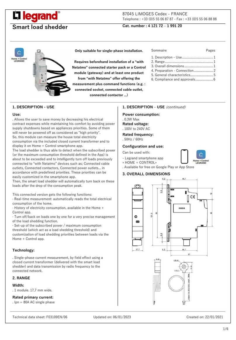
LEGRAND 4 121 72 Instruction Manual

LEGRAND

LEGRAND 4 121 72 Instruction Manual

LEGRAND Practibox S 1 34 Series User manual

LEGRAND

LEGRAND Practibox S 1 34 Series User manual

LEGRAND bticino RCP User manual

LEGRAND

LEGRAND bticino RCP User manual

LEGRAND Wattstopper DSW-100 User manual

LEGRAND

LEGRAND Wattstopper DSW-100 User manual

LEGRAND 4 052 20 User manual

LEGRAND

LEGRAND 4 052 20 User manual

LEGRAND MOSAIC II 766 55 User manual

LEGRAND

LEGRAND MOSAIC II 766 55 User manual

LEGRAND 4 122 20 User manual

LEGRAND

LEGRAND 4 122 20 User manual

LEGRAND MS Series Installation guide

LEGRAND

LEGRAND MS Series Installation guide

Popular Industrial Electrical manuals by other brands

Murata GRM1555C1E2R0BA01 Series Reference sheet

Murata

Murata GRM1555C1E2R0BA01 Series Reference sheet

Murata GRM0335C2A560JA01 Series Reference sheet

Murata

Murata GRM0335C2A560JA01 Series Reference sheet

Murata GRM216R71E182KA01 Series Reference sheet

Murata

Murata GRM216R71E182KA01 Series Reference sheet

Murata GJM0335C1E9R1BB01 Series Reference sheet

Murata

Murata GJM0335C1E9R1BB01 Series Reference sheet

Murata GRM1885C1H7R6CA01 Series Reference sheet

Murata

Murata GRM1885C1H7R6CA01 Series Reference sheet

Murata GRM188R71H223MA01 Series Reference sheet

Murata

Murata GRM188R71H223MA01 Series Reference sheet

Murata GQM22M5C2H180FB01 Series Reference sheet

Murata

Murata GQM22M5C2H180FB01 Series Reference sheet

Murata GQM2195C2E470GB12 Series Reference sheet

Murata

Murata GQM2195C2E470GB12 Series Reference sheet

Murata GRM31CR71A475KA01 Series Reference sheet

Murata

Murata GRM31CR71A475KA01 Series Reference sheet

Murata GRM32DR60J336ME19 Series Reference sheet

Murata

Murata GRM32DR60J336ME19 Series Reference sheet

Murata GRM216R71H822KA01 Series Reference sheet

Murata

Murata GRM216R71H822KA01 Series Reference sheet

Festo Pneumatic FSS-I 2 operating instructions

Festo Pneumatic

Festo Pneumatic FSS-I 2 operating instructions

CommScope SYSTIMAX 360 360G2 4U Series instruction sheet

CommScope

CommScope SYSTIMAX 360 360G2 4U Series instruction sheet

Festo IPC FEC FC34 Brief description

Festo

Festo IPC FEC FC34 Brief description

hager univers Z UF21NW Mounting instructions

hager

hager univers Z UF21NW Mounting instructions

Murata GRM1555C1H121GA01 Series Reference sheet

Murata

Murata GRM1555C1H121GA01 Series Reference sheet

Murata GQM22M5C2H1R2BB01 Series Reference sheet

Murata

Murata GQM22M5C2H1R2BB01 Series Reference sheet

Rockwell Automation Allen-Bradley 2090-KTPC-MA-AA installation instructions

Rockwell Automation

Rockwell Automation Allen-Bradley 2090-KTPC-MA-AA installation instructions

manuals.online logo
manuals.online logoBrands
  • About & Mission
  • Contact us
  • Privacy Policy
  • Terms and Conditions

Copyright 2025 Manuals.Online. All Rights Reserved.