manuals.online logo
Brands
  1. Home
  2. •
  3. Brands
  4. •
  5. LEGRAND
  6. •
  7. Intercom System
  8. •
  9. LEGRAND On-Q inQuire 1000 User manual

LEGRAND On-Q inQuire 1000 User manual

301 Fulling Mill Road, Suite G
Middletown, PA 17057
Phone (800) 321-2343 / Fax (717) 702-2546
www.onqlegrand.com
Page 1 of 3
INSTRUCTION/INSTALLATION SHEET
inQuire™ 1000 Intercom Main Console
Unit
IS-0339 REV. O
©Copyright 2006 by On-Q/Legrand All Rights Reserved.
1. Introduction
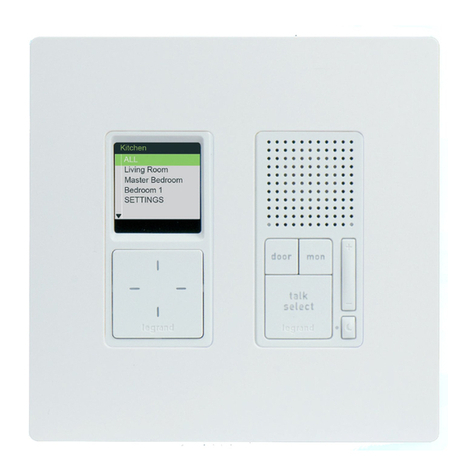
You have purchased the On-Q/Legrand inQuire™ 1000
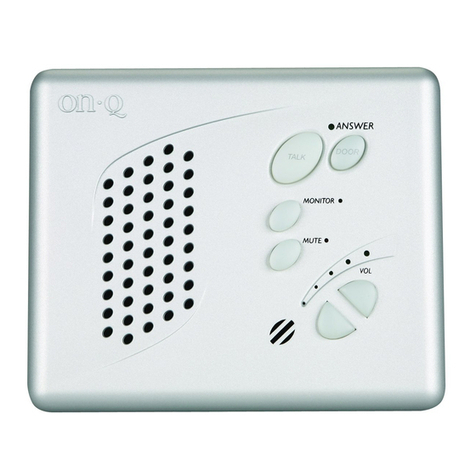
Intercom Main Console Unit, IC1003-xx (see Figure 1).
The Main Console provides basic intercom
communications functions such as talk, talk to door,
monitor and mute plus a status of all Room Units,
Desktop Units and Patio Units. The Main Console is
available in white (-WH), ivory (-IV), or light almond (-
LA).
2. Description
The inQuire™ 1000 Intercom Main Console Unit is
attached to the inQuire™ 1000 Intercom Module located
in the enclosure via two “home run” Cat 5e cables. The
Main Console is typically placed at switch height in a
central location (like the kitchen) and is used to
communicate with all other Room, Patio, or Door Units.
It provides status lights to indicate which Room or Patio units are talking, muted, or in monitor mode. It also
includes a dedicated Door Release button which is functional if the appropriate electric door release hardware
is installed.
3. Installation
Installation of the inQuire™ 1000 Intercom Main Console Unit is best accomplished at multiple times during
new construction, at “Rough-in” before the drywall is installed, and at “Trim-out” after the drywall is installed
and painted.
A. “Rough-in” steps:
1. Run two Cat 5e cables from the Enclosure where the Intercom Module will be installed to the 3 gang
box located at switch level height at the Main Console Unit location.
NOTE: It is important to keep all Category 5e cable runs, regardless of use, at least 12 inches
away from AC electrical cables. If it proves necessary to cross an existing AC cable, do so only at
a 90 degree angle.
B. “Trim-out” steps:
NOTE: All terminations can be correctly completed by following the T568A pin assignments. It is
important that you accurately terminate using T568A at all locations. There are two different types of
terminations you will encounter when installing the inQuire™ 1000 Intercom System: RJ45 plugs on the
Modules, the Main Console and the Room Unit and 110 punchdown blocks on Door and Patio Units. Refer
to Figure 2 for correct T568A termination for both RJ45 plugs and 110 punchdown blocks.
Figure 1
301 Fulling Mill Road, Suite G
Middletown, PA 17057
Phone (800) 321-2343 / Fax (717) 702-2546
www.onqlegrand.com
Page 2 of 3
INSTRUCTION/INSTALLATION SHEET
inQuire™ 1000 Intercom Main Console
Unit
IS-0339 REV. O
©Copyright 2006 by On-Q/Legrand All Rights Reserved.
1. As shown in Figure 3, label and connectorize the two Cat 5e cables onto the RJ-45 jacks on the rear of
the Main Console Unit. Follow the T568A standards described in Figure 2.
2. Insert the Main Console Unit in position and the Cat 5e cables into the 3 gang box and secure the unit
to the box using the 6 included screws.
3. Terminate the other end of the labeled Cat 5e cables, at the Intercom Module, with RJ45 plugs using
the T568A wiring standard.
4. Insert the RJ45 plugs into the appropriate “Main”
jacks on the Intercom Module in the enclosure (see
Figure 4).
5. Apply power to the Intercom Module and verify system functionality.
Figure 3
Figure 2
Main jacks
Figure 4
301 Fulling Mill Road, Suite G
Middletown, PA 17057
Phone (800) 321-2343 / Fax (717) 702-2546
www.onqlegrand.com
Page 3 of 3
INSTRUCTION/INSTALLATION SHEET
inQuire™ 1000 Intercom Main Console
Unit
IS-0339 REV. O
©Copyright 2006 by On-Q/Legrand All Rights Reserved.
4. Operation
Please refer to Figure 5 to familiarize yourself with the operation of the inQuire™ 1000 Main Console Unit.
Figure 5
TALK: Depressing this button will allow you to communicate
with all other active units. Hold in the TALK button while
speaking, and let it go when you are done. Your voice will be
heard on any active Room, Patio, or Desktop Unit within the
system.
ANSWER LED: This LED is located at the top of the keypad.
When lit, the LED indicates that the microphone in the unit is
active and anything you say will be communicated through the
system. This LED will light when you are depressing the TALK
or DOOR buttons.
TALK HANDS FREE: Press and hold this button while talking
to put all active Room Units in Hands Free Mode. All active (not
in Mute or Monitor Mode) Room Unit’s microphones are
activated, so that other intercom users can communicate
without pressing their TALK buttons. The Hands Free Mode
stays in effect for 20-30 seconds or until the TALK HANDS
FREE button on the Main Console is pressed again.
DOOR: Depressing this button will allow you to communicate
with all Door Units that are part of your system. Hold in the
DOOR button while speaking and let it go when you are done.
Your voice will be heard on any active Room, Patio, or Desktop
Units and all Door Units within the system.
DOOR RELEASE: Pressing the DOOR RELEASE button will
engage the door release device (not included with the Intercom
System) if a door release device is installed. Once you let go of
the button, the door release device will be disengaged, which will
lock the door again.
STATUS LEDs: Each LED indicates the status of each Room Unit in the
system. A GREEN light indicates that the Room Unit’s Talk or Door button is
depressed and someone is talking with the unit. A RED light indicates that the
Room Unit is in MUTE mode and that all speaker and microphone functions of
the unit are disabled. An ORANGE light indicates that the unit is in Monitor
mode and its microphone is currently active. Pre-printed and blank labels are
included in the package to identify LEDs.
PATIO UNIT DISABLE: If a Patio Unit is installed in Port #11
and security mode was enabled by removing the shunt on J3 on
the rear of the Intercom Module, the Patio Unit can be disabled
temporarily by simultaneously pressing and releasing the TALK
and DOOR RELEASE buttons on the Main Console Unit. The
Patio Unit Status LED should blink slowly Red and then Green.
To re-enable the Patio Unit, again simultaneously press and
release the TALK and DOOR RELEASE buttons on the Main
Console Unit.
VOLUME: There are two volume control buttons with an
associated volume level LED bar. There are 20 different volume
levels which are adjusted up and down using these two buttons.
Pressing the volume up button once will increase the volume
one level higher. You may not see the LEDs change until you
press the volume up or down multiple times (approximately
every sixth button press). You can also hold in the volume up or
down button until you have reached the desired volume level. It
is recommended that you keep the volume level in the middle
position (3 LEDs lit) for optimum sound quality.
KEYPAD BRIGHTNESS:
If the default Dim level of the backlit buttons is not adequate for
the user, then press both Volume buttons at the same time and
release them. Use the Up or Down Volume button to brighten or
dim the default backlight level. When the desired level is
reached, either push both buttons at the same time again to
resume normal operation, or just let the Unit time out (after
about 10 seconds) to return to normal operation.
NOTE: When in use, the Unit’s backlight level is at full
brightness and returns to the set backlight Dim level upon
timeout (about 10 seconds).
Other LEGRAND Intercom System manuals

LEGRAND Tynetec Advent XT2 User manual

LEGRAND

LEGRAND Tynetec Advent XT2 User manual

LEGRAND 369325 User manual

LEGRAND

LEGRAND 369325 User manual

LEGRAND LEGD365 061 User manual

LEGRAND

LEGRAND LEGD365 061 User manual

LEGRAND Easy Kit Connected User manual

LEGRAND

LEGRAND Easy Kit Connected User manual

LEGRAND AI6100M1 User manual

LEGRAND

LEGRAND AI6100M1 User manual

LEGRAND HPM D642/01 User manual

LEGRAND

LEGRAND HPM D642/01 User manual

LEGRAND EASYKIT Essential User manual

LEGRAND

LEGRAND EASYKIT Essential User manual

LEGRAND HPM D642/012R User manual

LEGRAND

LEGRAND HPM D642/012R User manual

LEGRAND On-Q User manual

LEGRAND

LEGRAND On-Q User manual

LEGRAND D45 SYSTEM User manual

LEGRAND

LEGRAND D45 SYSTEM User manual

LEGRAND 369339 User manual

LEGRAND

LEGRAND 369339 User manual

LEGRAND 369305 User manual

LEGRAND

LEGRAND 369305 User manual

LEGRAND IC7000 User manual

LEGRAND

LEGRAND IC7000 User manual

LEGRAND BTicino MyHome HOMETOUCH3488 User manual

LEGRAND

LEGRAND BTicino MyHome HOMETOUCH3488 User manual

LEGRAND CM2001 User manual

LEGRAND

LEGRAND CM2001 User manual

LEGRAND IC7001 User manual

LEGRAND

LEGRAND IC7001 User manual

LEGRAND 41648 User manual

LEGRAND

LEGRAND 41648 User manual

LEGRAND 369220 User manual

LEGRAND

LEGRAND 369220 User manual

LEGRAND EASYKIT Connected User manual

LEGRAND

LEGRAND EASYKIT Connected User manual

LEGRAND 369205 User manual

LEGRAND

LEGRAND 369205 User manual

LEGRAND AI6100M1 User manual

LEGRAND

LEGRAND AI6100M1 User manual

LEGRAND AI6100M1 User manual

LEGRAND

LEGRAND AI6100M1 User manual

LEGRAND 0 416 51 User manual

LEGRAND

LEGRAND 0 416 51 User manual

LEGRAND ON-Q IC5002-OB User guide

LEGRAND

LEGRAND ON-Q IC5002-OB User guide

Popular Intercom System manuals by other brands

Bpt DVC/08 Programming manual

Bpt

Bpt DVC/08 Programming manual

golmar T500EN instruction manual

golmar

golmar T500EN instruction manual

Shideantec SD-880RC16-DC1001 manual

Shideantec

Shideantec SD-880RC16-DC1001 manual

NTEK DOORPAD product manual

NTEK

NTEK DOORPAD product manual

Rocom Agora IP quick guide

Rocom

Rocom Agora IP quick guide

Mercury 350.296UK user manual

Mercury

Mercury 350.296UK user manual

Farfisa Sette SE4252 manual

Farfisa

Farfisa Sette SE4252 manual

Bticino 369211 installation manual

Bticino

Bticino 369211 installation manual

Clas Ohlson JH-834-2 quick start guide

Clas Ohlson

Clas Ohlson JH-834-2 quick start guide

Longix LE-T1000 installation guide

Longix

Longix LE-T1000 installation guide

NEXhome IS-T102 quick start guide

NEXhome

NEXhome IS-T102 quick start guide

DoorBird D1101UV installation manual

DoorBird

DoorBird D1101UV installation manual

Studio Technologies 370A user guide

Studio Technologies

Studio Technologies 370A user guide

AYR 763 user manual

AYR

AYR 763 user manual

Emos H1016 user manual

Emos

Emos H1016 user manual

Toa N-8031MS Specifications

Toa

Toa N-8031MS Specifications

RTS PAP-32 user manual

RTS

RTS PAP-32 user manual

Wahsega Outdoor Pedestal Installer's guide

Wahsega

Wahsega Outdoor Pedestal Installer's guide

manuals.online logo
manuals.online logoBrands
  • About & Mission
  • Contact us
  • Privacy Policy
  • Terms and Conditions

Copyright 2025 Manuals.Online. All Rights Reserved.