manuals.online logo
Brands
  1. Home
  2. •
  3. Brands
  4. •
  5. LEGRAND
  6. •
  7. Lighting Equipment
  8. •
  9. LEGRAND G5 VISION 61774 User manual

LEGRAND G5 VISION 61774 User manual

9
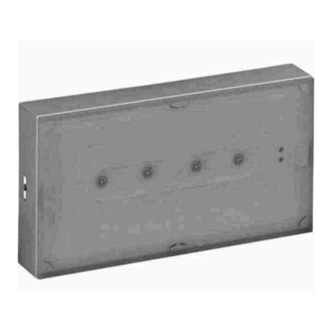
G5 VISION self-contained emergency lighting unit
617 74/75/76
Presentation
Technical characteristics
Fixing
E49108
The G5 VISION series of self-contained emergency lighting units
automatically check switching to operating status every week and the
battery standby power every 13 weeks. The illuminated signalling of
two LEDs permanently indicates the unit status.
They have two operating modes, "automatic control" or "addressable",
which can be selected using the micro-switches on the printed circuit.
- In "automatic control" mode (all micro-switches in position "1"), the
emergency lighting unit is 100 % compatible with those of previous
generations.
- In "addressable" mode (micro-switches positioned according to the
address assigned to the unit), the emergency lighting unit uses a
special line which operates as a data BUS. An interface module
connects the BUS to a PC, which performs the installation supervision
function.
IMPORTANT: in addressable mode all the emergency lighting units
connected to the interface module must be G5 VISION series units
operating in "addressable" mode (valid address).
CAT. No.
AC Power Supply CHARACTERISTICS
Power Supply
Consumption
Emergency
lumen output Emergency
duration
IP-IK Combined
61774
61775
61776
230 V
50/60 Hz
85 mA
85 mA
85 mA
235
145
310
1 h
3 h
1 h
2 X 8 W
2 X 8 W
2 X 8 W
42-07
42-07
42-07
C
C
C
10
Raccordement
Addressing
In "addressable" mode, use the BTI interface module as shown in the diagram below
IMPORTANT: beyond the BTI interface module, there should only b e G5 VISION series emergency lighting units in
"addressable" mode.
To connect the BTI interface module, see its accompanying manua l. A detailed installation and commissioning procedure is
described in the "Installation" section of the manual "Technica l guide for a URAVISION installation". This manual also gives a ll the
information on how to create mixed installations containing sta ndard units and G5 VISION units in "automatic control" or
"addressable" mode..
Commissioning
"Automatic control" mode
Switch on the installation.
Check that the green LED is lit, and also the maintained tube o f the combined units.
Leave the unit on charge for 1 hr and then switch off the mains supply to the units.
Check that the emergency tube lights up.
Switch the installation back on.
"Addressable" mode
A detailed addressing, installation and commissioning procedure is described in the "Installation" section of the manual
"Technical guide for a URAVISION installation".
• Commissioning the units and the interface module
As the supervision software is not running, switch on the insta llation (BTI and emergency lighting units in "addressable" mode ).
If the green and yellow LEDs are flashing alternately (15 s.), the BUS is not connected to the emergency lighting unit or the poles
have been reversed, check the BUS wiring.
Check that the green LED is lit, and also the maintained tube o f the combined units (mains power present).
Check that the "battery charging" and BUS LEDs are lit on the B TI interface module (mains power and voltage present on the BUS ).
• Commissioning the supervisory PC
Install the supervision software on the PC in accordance with t he instructions in its accompanying manual.
Start up the supervision software and wait for it to scan all t he units in the installation.
IMPORTANT: check the emergency lighting unit wiring. Any revers ed wires between the mains power supply and the BUS
will cause irreversible damage to the emergency lighting units and the BTI interface module.
Caution: if the wires between the power supply and the BUS are reversed, the unit will be damaged permanently.
L=brown N=Blue L’=Grey A+=Red B-=Black
11
Operation
IMPORTANT: The unit may have lost the initialisation performed at the time of first switch-on if the installation has been
switched off for a long period, resulting in total discharging of the battery (1 month with a charged battery / 24 hours
with a discharged battery if the installation has been operating on standby power after a power cut). In this case, the
test time is initialised again at a random time when the installation is switched back on. If necessary, the units can then
be reprogrammed individually or centrally.
Remote control:
Remote commands can be sent from pushbuttons located on the interface module or from the supervisory PC. The OFF
command can be used to switch off emergency lighting units when deliberately disconnecting the mains to avoid discharging
the batteries. The ON command can be used to re-illuminate the emergency lighting units using battery power, if necessary.
The commands are only active when the mains is not present. Once the mains is restored, the emergency lighting units
automatically return to standby mode whatever their previous status.
The BTI interface module must be powered up permanently. If the power supply fails, the link between the units and the
supervisory PC is no longer assured and the units will be declared as having a communication fault. Only the ON and OFF
commands are backed up by the interface module internal battery.
Automatic sequence after power-up:
- First the emergency lighting unit recharges its battery for 24 hrs and then performs a quarterly test.
- Next the emergency lighting unit recharges its battery for 24 hrs in order to be fully operational.
Switching:
- After a power cut, when the mains supply is restored, the emergency lighting unit remains on standby power for 30 seconds
so as to allow the normal lighting luminaires to come back on.
- If the batteries have discharged completely, a safety device prevents switching to emergency mode until the batteries have
partially recharged
Maintained test with the mains power on:
- Charger test
- Battery voltage test
- Maintained tube test
Note: a fault on the maintained tube is only signalled when the mains is present on the L' input. It is cleared as soon as the
mains disappears from this input.
Weekly test:
- This test checks switching to emergency mode in the event of mains power failure and illumination of the emergency tube.
This test lasts 15 seconds.
During the test, battery charging is interrupted.
- This test can only be performed with mains power present and if the battery is partially charged (3 hours of mains presence
after a complete discharge). If not, the test is postponed until mains power is restored and the battery is sufficiently recharged.
Quarterly test:
- This test checks the nominal standby power on the emergency tube. During the test, battery charging is interrupted.
- This test can only be performed with mains power present and if the battery is almost fully charged (22 hours of mains
presence after a complete discharge). If not, the test is postponed until mains power is restored and the battery is sufficiently
recharged.
- If the test is interrupted by a remote OFF command, it will automatically be carried over to the next day.
- An additional quarterly test can be initiated manually by pressing the unit pushbutton for more than 5 seconds. If the test
cannot be performed immediately because the battery is insufficiently charged, the green and yellow LED’s are flashing for 15
seconds. If a test is being carried over, this is cancelled.
- In "automatic control" mode, initiating this test also prompts programming the time of the tests as described below.
Test maintenance:
- An maintenance test can be initiated manually by briefly pressing the unit pushbutton (15 seconds). If the test cannot be
performed immediately because the battery is insufficiently charged, the green LED flashes for 10 seconds.
Three programming options:
1) No programming:
- If they have not been programmed, the units will perform their tests at a random time after they have been switched on for the
first time. The test times are split over a period of 64 days to ensure that two adjacent units are not undergoing tests on the
same day. Weekly tests are performed on the same day of the week and at the same time as the quarterly test.
2) Individual programming ("automatic control" mode only):
- In "automatic control" mode, the units are programmed by pressing the pushbutton on the reflector for 5 seconds. This action
is performed once only during commissioning, on the day and at the time chosen for the tests to be performed. This should
be done after the units have been switched on for the first time.
3) Centralised programming ("addressable" mode only):
- To program the test time in "addressable" mode, see the "Technical guide for a URAVISION installation" and the supervision
software (PC) manual.
12
Maintenance
Servicing
The meaning of the two LEDs is as follows:
- Green lit = emergency lighting unit operating normally
- Green flashing = test in progress
- Yellow lit steady = tube faulty with mains present or in emergency mode -->
- Change the maintained tube of a combined unit if it has gone out
- Press the pushbutton briefly to start an maintenance test
- Change the emergency tube if it does not light up
- Yellow flashing slowly = battery fault --> replace the batteries and repeat the same procedure as for the first time of use
- Yellow flashing quickly = fault in the electronics --> send the emergency lighting unit to be repaired.
In "addressable" mode, the faults are transferred to the supervisory PC (see the software manual for further details).
Any appliance which is found to be faulty should be repaired as quickly as possible.
Batteries : The battery should be replaced every 4 years or when the emergency lighting unit does not reach its nominal standby
power. The storage cells used in this appliance contain cadmium, which is harmful to the environment as outlined in European
directive 91/157/EEC of 18/03/91. Once used, please consult the appropriate authorities or return the batteries to us for recycling.
Lamp: The fluorescent lamp should be replaced with a lamp specified by the manufacturer.

This manual suits for next models

2

Other LEGRAND Lighting Equipment manuals

LEGRAND 0 580 10 User manual

LEGRAND

LEGRAND 0 580 10 User manual

LEGRAND CONNECTRAC User manual

LEGRAND

LEGRAND CONNECTRAC User manual

LEGRAND LED SATELLITE User manual

LEGRAND

LEGRAND LED SATELLITE User manual

LEGRAND Kenall MRIMAS Series User manual

LEGRAND

LEGRAND Kenall MRIMAS Series User manual

LEGRAND Wattstopper LMRC-102 User manual

LEGRAND

LEGRAND Wattstopper LMRC-102 User manual

LEGRAND 0 880 61 User manual

LEGRAND

LEGRAND 0 880 61 User manual

LEGRAND KENALL MILLENIUM METREX METSW Series User manual

LEGRAND

LEGRAND KENALL MILLENIUM METREX METSW Series User manual

LEGRAND URA21LED User manual

LEGRAND

LEGRAND URA21LED User manual

LEGRAND 628 25 User manual

LEGRAND

LEGRAND 628 25 User manual

LEGRAND 0 648 88 User manual

LEGRAND

LEGRAND 0 648 88 User manual

LEGRAND HPM LLF024K1200 User manual

LEGRAND

LEGRAND HPM LLF024K1200 User manual

LEGRAND DLI90BTWE User manual

LEGRAND

LEGRAND DLI90BTWE User manual

LEGRAND 6 624 52 User manual

LEGRAND

LEGRAND 6 624 52 User manual

LEGRAND 0 883 05 User manual

LEGRAND

LEGRAND 0 883 05 User manual

LEGRAND 0 405 10 User manual

LEGRAND

LEGRAND 0 405 10 User manual

LEGRAND BH4NDWE User manual

LEGRAND

LEGRAND BH4NDWE User manual

LEGRAND WP2 LED User manual

LEGRAND

LEGRAND WP2 LED User manual

LEGRAND adorne ADWR700MMTU User manual

LEGRAND

LEGRAND adorne ADWR700MMTU User manual

LEGRAND Bulkhead 265 LED User manual

LEGRAND

LEGRAND Bulkhead 265 LED User manual

LEGRAND Kenall SENSCAPE SPG18 User manual

LEGRAND

LEGRAND Kenall SENSCAPE SPG18 User manual

LEGRAND CP Electronics Vitesse Modular User manual

LEGRAND

LEGRAND CP Electronics Vitesse Modular User manual

LEGRAND 025626 User manual

LEGRAND

LEGRAND 025626 User manual

LEGRAND Adorne APCC User manual

LEGRAND

LEGRAND Adorne APCC User manual

LEGRAND LCS 0 337 53 User manual

LEGRAND

LEGRAND LCS 0 337 53 User manual

Popular Lighting Equipment manuals by other brands

Life 39.9F70020C quick start guide

Life

Life 39.9F70020C quick start guide

EuroLite LED ML-20 user manual

EuroLite

EuroLite LED ML-20 user manual

LIGMAN OD-50141 installation manual

LIGMAN

LIGMAN OD-50141 installation manual

Home Accents Holiday 1002461144 instructions

Home Accents Holiday

Home Accents Holiday 1002461144 instructions

Experia IRiS Ripple Light instruction manual

Experia

Experia IRiS Ripple Light instruction manual

Erco Gecko Mounting instructions

Erco

Erco Gecko Mounting instructions

Inter-lux ZTA.100.Surface Installation and maintenance instructions

Inter-lux

Inter-lux ZTA.100.Surface Installation and maintenance instructions

Whelen Engineering Company TN Series installation guide

Whelen Engineering Company

Whelen Engineering Company TN Series installation guide

IKEA BJÖRKSPIREA manual

IKEA

IKEA BJÖRKSPIREA manual

Toolland PM 6640 instruction manual

Toolland

Toolland PM 6640 instruction manual

GTD GTD-LP200 user manual

GTD

GTD GTD-LP200 user manual

LIVARNO home 1105-W-UK manual

LIVARNO home

LIVARNO home 1105-W-UK manual

ProLights EclPar IPMFC user manual

ProLights

ProLights EclPar IPMFC user manual

Velvet EVO Series user manual

Velvet

Velvet EVO Series user manual

IDTOLIGHT GENT installation instructions

IDTOLIGHT

IDTOLIGHT GENT installation instructions

MAYTONI S35 installation manual

MAYTONI

MAYTONI S35 installation manual

MaxLite MLFP14DP4535 user manual

MaxLite

MaxLite MLFP14DP4535 user manual

SLV Elektronik 550621 instruction manual

SLV Elektronik

SLV Elektronik 550621 instruction manual

manuals.online logo
manuals.online logoBrands
  • About & Mission
  • Contact us
  • Privacy Policy
  • Terms and Conditions

Copyright 2025 Manuals.Online. All Rights Reserved.