Leica RM2125 User manual

Leica RM2125/
Leica RM2125RT
Rotary microtome
Instruction manual
Leica RM2125 / RM2125RT
V2.3 English - 02/2009
Always keep this manual together with the instrument.
Read carefully before working with the instrument.


3
Leica RM2125
NOTE
The information, numerical data, notes and val-
ue judgments contained in this manual repre-
sent the current state of scientific knowledge
and state-of-the-art technology as we under-
stand it following thorough investigation in this
field.
We are under no obligation to update the
present manual according to the latest techni-
cal developments, nor to provide our customers
with additional copies, updates etc. of this man-
ual.
For erroneous statements, drawings, technical
illustrations etc. contained in this manual we
exclude liability as far as permissible according
to the national legal system applicable in each
individual case. In particular, no liability what-
soever is accepted for any financial loss or con-
sequential damage caused by or related to
compliance with statements or other informa-
tion in this manual.
Statements, drawings, illustrations and other in-
formation as regards contents or technical de-
tails of the present manual are not to be consid-
ered as warranted characteristics of our
products.
These are determined only by the contract pro-
visions agreed between ourselves and our cus-
tomers.
Leica reserves the right to change technical
specifications as well as manufacturing pro-
cesses without prior notice. Only in this way is it
possible to continuously improve the technolo-
gy and manufacturing techniques used in our
products.
This document is protected under copyright
laws. Any copyrights of this document are re-
tained by Leica Biosystems Nussloch GmbH.
Any reproduction of text and illustrations (or of
any parts thereof) by means of print, photocopy,
microfiche, web cam or other methods – includ-
ing any electronic systems and media – re-
quires express prior permission in writing by Le-
ica Biosystems Nussloch GmbH.
For the instrument serial number and year of
manufacture, please refer to the name plate at
the back of the instrument.
© Leica Biosystems Nussloch GmbH
Published by:
Leica Biosystems Nussloch GmbH
Heidelberger Str. 17 - 19
D-69226 Nussloch
Germany
Phone: +49 (0) 6224 143-0
Fax: +49 (0) 6224 143-2 00
Internet: http://www.histo-solutions.com

4Instruction manual V 2.3 – 02/2009
Table of contents
1. Important notes .................................................................................................................................................................................... 5
1.1 Symbols in the text and their meaning ....................................................................................................................................................... 5
1.2 Qualification of personnel ............................................................................................................................................................................. 5
1.3 Designated use ............................................................................................................................................................................................... 5
1.4 Instrument type ............................................................................................................................................................................................... 5
2. Safety ..................................................................................................................................................................................................... 6
2.1 Safety instructions ......................................................................................................................................................................................... 6
2.2 Warnings .......................................................................................................................................................................................................... 6
2.3 Integrated safety devices ............................................................................................................................................................................. 8
3. Instrument components and specifications .................................................................................................................................. 10
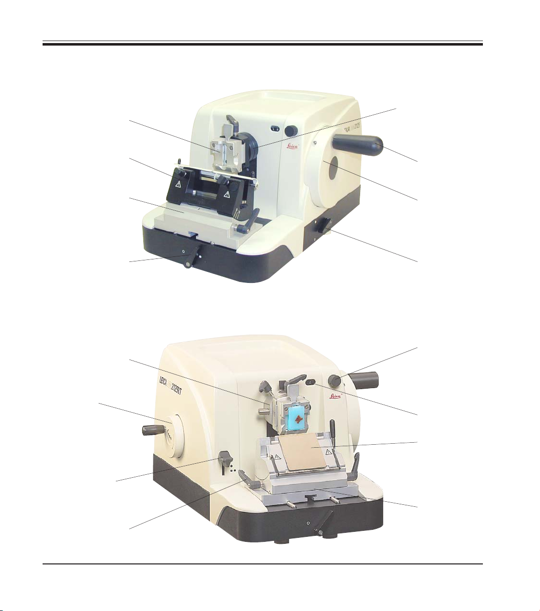
3.1 Overview - instrument components .......................................................................................................................................................... 10
3.2 Instrument specifications ........................................................................................................................................................................... 11
3.3 Technical data .............................................................................................................................................................................................. 12
4. Setup .................................................................................................................................................................................................... 13
4.1 Installation site requirements .................................................................................................................................................................... 13
4.2 Standard delivery ......................................................................................................................................................................................... 13
4.3 Unpacking andinstallation .......................................................................................................................................................................... 14
4.4 Inserting the specimen clamp .................................................................................................................................................................... 15
4.5 Fastening the specimen clamp directly to the fixture ............................................................................................................................ 16
4.6 Mounting the knife holder base ................................................................................................................................................................. 17
4.7 Mounting the knife holder ........................................................................................................................................................................... 17
5. Operation ............................................................................................................................................................................................. 18
5.1 Clamping the specimen ............................................................................................................................................................................... 18
5.2 Inserting the knife / disposable blade ....................................................................................................................................................... 18
5.3 Adjusting the clearance angle ................................................................................................................................................................... 19
5.4 Orienting the specimen (possible only with orienting fixture for specimen clamps) ...................................................................... 20
5.5 Trimming the specimen ............................................................................................................................................................................... 21
5.6 Sectioning ...................................................................................................................................................................................................... 23
5.7 Changing specimen ...................................................................................................................................................................................... 23
5.8 Accessories ................................................................................................................................................................................................... 24
5.8.1 Standard specimen clamp .......................................................................................................................................................................... 24
5.8.2 Vee insert ....................................................................................................................................................................................................... 24
5.8.3 Foil clamp type 1 ........................................................................................................................................................................................... 25
5.8.4 Foil clamp type 2 ........................................................................................................................................................................................... 26
5.8.5 Universal cassette clamp ............................................................................................................................................................................ 26
5.8.6 Holder for round specimens ....................................................................................................................................................................... 27
5.8.7 Knife holder base .......................................................................................................................................................................................... 28
5.8.8 Knife holder N ............................................................................................................................................................................................... 29
5.8.9 Knifeholder E ................................................................................................................................................................................................. 30
5.8.10 Overview - accessories ............................................................................................................................................................................... 33
5.9 Optional accessories (ordering information) .......................................................................................................................................... 34
6. Cleaning and maintenance ............................................................................................................................................................. 35
6.1 Cleaning the instrument .............................................................................................................................................................................. 35
6.2 Maintenance instructions ........................................................................................................................................................................... 37
7. Troubleshooting ................................................................................................................................................................................. 38
7.1 Possible errors .............................................................................................................................................................................................. 38
7.2 Malfunction ................................................................................................................................................................................................... 38
8. Warranty and service ....................................................................................................................................................................... 39
EC Declaration of Conformity ........................................................................................................................................................... 40

5
Leica RM2125
Notes, i.e. important user information
appear in a gray box and are marked
by an information symbol .
Dangers, warnings and cautions ap-
pear in a grey box and are marked by
a warning triangle .
1.1 Symbols in the text and their meaning
1. Important notes
(5)
1.3 Designated use
The Leica RM2125 / Leica RM2125RT are manu-
ally operated rotary microtomes, used to pro-
duce thin sections of specimens of different
hardness in both routine and research applica-
tions in biology, medicine and industry.
They are designed to section soft materials em-
bedded in paraffin as well as harder specimens,
provided those specimens are still suitable for
manual sectioning.
Any other use of the instrument is considered
improper!
1.4 Instrument type
All information provided in this manual applies
only to the instrument type indicated on the cov-
er page.
A name plate indicating the instrument serial
number is attached to the back of the instru-
ment.
Fig. 1
1.2 Qualification of personnel
• The Leica RM 2125 may be operated only by
trained laboratory personnel.
• All laboratory personnel designated to oper-
ate the Leica RM2125 must read this instruc-
tion manual carefully and must be familiar
with all technical features of the instrument
before attempting to operate the Leica
RM2125.
Figures in brackets refer to item num-
bers in drawings.

6Instruction manual V 2.3 – 02/2009
Be sure to comply with the safety instructions and warnings in this chapter. Be sure to read
these instructions, even if you are already familiar with the operation and use of other Leica
products.
2. Safety
2.1 Safety instructions
This instruction manual contains important in-
structions and information regarding the opera-
tional safety and maintenance of the instrument.
The instruction manual is an important part of
the product, which must be read carefully prior
to setup and use and must always be kept near
the instrument.
.
If additional requirements on accident
prevention and environmental protec-
tion exist in the country of operation,
this instruction manual must be
supplemented by appropriate instruc-
tions to ensure compliance with such
requirements.
This instrument was built and tested in accor-
dance with machinery directive
98/37/EC and the safety regulations for laborato-
ry devices as specified below:
The latest information on the standards applied
can be found in the CE declaration of conformity
on the Internet under:
www. histo-solutions.com
The protective devices on both instrument and accessories may neither be removed nor modi-
fied. Only authorized and qualified service personnel may repair the instrument and access the
instrument’s internal components.
2.2 Warnings
The safety devices installed in this instrument by the manufacturer only constitute the basis for ac-
cident prevention.
Primarily responsible for accident-free operation is above all the institution which owns the instru-
ment and, in addition, the designated personnel who operates, services or cleans the instrument.
To ensure trouble-free operation of the instrument, make sure to comply with the following instruc-
tions and warnings.
In order to maintain this condition and ensure
safe operation, the operator must observe all
the instructions and warnings contained in this
instruction manual.

7
Leica RM2125
2. Safety
Warnings - safety instructions / warning labels attached to the instrument
• Safety instruction labels on the instrument marked with a warning triangle indicate that the
correct operating instructions (as described in this manual) must be followed when operating
or replacing the instrument component bearing the label.
Failure to adhere to these instructions may result in an accident, personal injury, damage to
the instrument or accessory equipment.
Warnings - Transport and installation
• Once uncrated, the instrument may only be transported in an upright position.
• For transport, do not grab the instrument neither by the handles of the handwheel or coarse
feed wheel nor by the section thickness adjusting knob.
• The protective devices on both instrument and accessories must neither be removed nor modi-
fied.
.
Warning - Operating the instrument
• Be very careful when handling microtome knives or blades. The knife or blade edges are ex-
tremely sharp and can cause severe injuries!
• Always remove the knife / blade before detaching the knife holder from the instrument. Knives
that are not in use should always be stored in the knife case!
• Never place a knife anywhere with the cutting edge facing upwards and never try to catch a
falling knife!
• Always clamp the specimen block BEFORE clamping the knife.
• Lock the handwheel and cover the knife edge with the knife guard prior to any manipulation of
knife or specimen, prior to changing the specimen block and during all work breaks!
• Always wear safety goggles when sectioning brittle specimens! Specimen may splinter!
• No fluid must enter the interior of the instrument during work!
• Leica RM2125 RT only:
Specimen blocks must not be oriented during the retraction phase.
If a block is oriented during retraction, prior to the next section the block will advance by the
retraction value PLUS the selected section thickness. This may cause damage to both speci-
men and knife!

8Instruction manual V 2.3 – 02/2009
Warnings - cleaning and maintenance
• Only authorized and qualified service personnel may repair the instrument and access the
instrument’s internal components.
• Lock the handwheel before you starting to clean the instrument!
• Do not use any solvents containing acetone or xylene for cleaning!
• No fluid must enter the interior of the instrument during cleaning!
• When using cleaners, comply with the safety instructions of the manufacturer and the labor-
safety regulations of your laboratory!
2.3 Integrated safety devices
The instrument is equipped with the following protection features:
2. Safety
Handwheel locking mechanism
The handwheel (15) can be locked in the 12-
o’clock position (Fig. 2).
When pushing the handwheel handle (1) in-
wards (to the left), the handwheel will lock in
place when next reaching the 12-o’clock posi-
tion.
Function check:
• To activate the locking mechanism, push the
handle (1) to the left. The handwheel locks in
place in the 12 o’clock position and cannot
be rotated any further.
• To unlock the handwheel, pull the handle (1)
outwards (to the right).
Handwheel brake
With the lever (2) on the right side of the micro-
tome base plate, the handwheel brake can be
activated with the handle in any position. When
the lever is pushed upward, the handwheel is
locked in position. Two symbols on the micro-
tome base plate indicate the ‘locked’ and ‘un-
locked’ position (Fig. 2).
Fig. 2
1
2
Lever in position = handwheel locked
Lever in position = handwheel released
15

9
Leica RM2125
Knife guard on the knife holder
All knife holders are equipped with a permanent knife guard (3, 5) capable
of covering the entire length of the knife / blade edge in any position.
Lock the handwheel and cover the knife edge with the knife guard
prior to any manipulation of knife or specimen, prior to changing
the specimen block and during all work breaks!
2. Safety
Knife holder N
The knife guard (3) of the knife holder N can be
easily positioned via the two buttons (4) (Fig. 3).
To cover the knife edge, push both cover strips
of the knife guard to the center.
Knife holder E
The knife guard of the knife holder E consists of
a hinged shackle (5).
To cover the edge, turn the shackle (5) upwards
as shown in Fig. 4.
4
4
3
Fig. 3
Fig. 4
5
5

10 Instruction manual V 2.3 – 02/2009
3.1 Overview - instrument components
3. Instrument components and specifications
Control knob
for section
thickness setting
Leica RM2125
Section
thickness
indication
Fixture for specimen
clamps, non-orientable
Clamping lever for
knife holder base
Smooth-turning
handwheel
Lever for activating
the handwheel
brake
Handwheel
handle with
locking
mechanism
Lever for activating
the mechanical
trimming function
Orientable fixture for
specimen clamps
Coarse feed
wheel
Leica RM2125 RT
Fig. 5
Fig. 6
Knife holder E
Knife holder N
Knife holder base
with lateral
displacement
feature
Knife holder base,
without lateral
displacement feature
Clamping lever for
lateral displacement
function of knife
holder
Universal
Cassette clamp

11
Leica RM2125
3. Instrument components and specifications
3.2 Instrument specifications
The Leica RM2125 and Leica RM2125 RT are manually operated rotary mi-
crotomes.
• The advance and vertical stroke mechanisms run on cross roller
guides that are free from backlash and maintenance-free. Both
mechanisms as well as the coarse feed system are protected by a
dust-proof plastic housing.
• The handwheel can be locked in the 12 o’clock position via the
handwheel handle. In addition, a handwheel brake mechanism allows
you to lock the handwheel in any position via a locking lever integrated
into the base plate.
• Sectioning is done manually by rotating the exceptionally smooth-run-
ning, counterbalanced handwheel. .
• The coarse feed function is operated via the coarse feed wheel on the
left side of the instrument housing.
• Section thickness is selected via a turning control knob and indicated
in the small window integrated into the instrument housing.
Section thickness settings from 0.5 to 60 μm can be selected.
• Both models are equipped with a slot cover preventing section waste
from entering the interior of the instrument.
Both the Leica RM2125 and Leica RM2125 RT are available in two ver-
sions:
1. Leica RM2125 / RM2125 RT, course-feed wheel left,
clockwise sense of rotation.
2. Leica RM2125 / RM2125 RT, course-feed wheel left,
counterclockwise sense of rotation.
The direction of feed of the coarse feed wheel is indicated by an arrow.
Leica RM2125 RT - additional features
• A mechanical trimming function, activated via a lever and featuring 10
μm and 50 μm trimming thickness.
• Specimen retraction, designed to protect both knife and specimen.
During the return stroke, the specimen is pulled back from the knife by
220 μm. Prior to the next section, the specimen advances by the se-
lected section thickness plus the retraction value.

12 Instruction manual V 2.3 – 02/2009
3.3 Technical data
General
Approvals: The instrument-specific marks are located on the
rear panel of the instrument next to the name plate
Operating temperature range: +10 °C to +40 °C
Section thickness setting range: 0.5 - 60 μm
Section thickness selection: from 0 - 2 μm in 0.5-μm steps
from 2 - 10 μm in 1-μm steps
from 10 - 20 μm in 2-μm steps
from 20 - 60 μm in 5-μm steps
Total horizontal specimen feed: 25 mm
Vertical specimen stroke: 59 mm
Specimen retraction (RM2125 RT only): 220 μm
Dimensions and weight
Width 400 mm
Depth 470 mm
Height 295 mm
Working height (knife edge) 105 mm
Weight (without accessories) 29 kg
Optional features and optional accessories
Specimen orientation (optional)
horizontal: 8 °
vertical: 8 °
Rotability: ± 90 °
Trimming thickness (RM2125 RT only): 10 μm, 50 μm
Knife holder base with lateral displacement feature:
north-south: ± 25 mm
east-west: ± 20 mm
Knife holder base without lateral displacement feature:
north-south: ± 25 mm
3. Instrument components and specifications

13
Leica RM2125
4. Setup
4.2 Standard delivery
The Leica RM2125 standard delivery includes:
1 Leica RM2125 basic instrument (without retraction) ............. 14 0457 37986
Basic instrument includes the following accessories:
1 Fixture for spec. clamps, orientable (attached to instrument) ...
14 0457 37990
1 Tool set - consisting of:
1 Allen key with handle, size 3 ............................................... 14 0194 04764
1 Allen key with handle, size 4 ................................................ 14 0194 04782
1 Allen key, size 8 ...................................................................... 14 0222 04143
1 bottle (50 ml) of oil for drives, type 405 ............................... 14 0336 06086
1 dust protective cover (104 R) ............................................... 14 0212 04091
1 Instructions manual (+ language-CD) ...................................... 14 0498 80001
The above accessories plus any further accessories you ordered you will
find in the cardboard box packed on top of the instrument (see Fig. 7).
Carefully check the delivery against the packing list, delivery note
and your order.
Should there be any discrepancy, please contact the Leica sales
unit handling your order or your Leica dealer.
4.1 Installation site requirements
• Stable, vibration-free laboratory bench with horizontal and even table
top; practically vibration-free floor.
• No other instruments nearby which might cause vibrations.
• Room temperature permanently between + 15 °C and + 40 °C.
• Unobstructed and convenient access to both handwheel and coarse
feed wheel.

14 Instruction manual V 2.3 – 02/2009
• Open the crate.
• Remove all accessories (1) and the instruc-
tion manual.
• Remove Allen key, size 8 and set aside.
• Remove cardboard tray (2).
• Remove cushioning material.
• Remove cardboard cover (3).
• Use the two straps (4) attached to the front
and back of the wooden pallet to remove the
instrument from the crate.
For transport, do not grab the instru-
ment neither by the handles of the
handwheel or coarse feed wheel nor
by the section thickness adjusting
knob.
• Place wood pallet with instrument onto a
stable bench.
• Grasp the front edge of the pallet and lift it
slightly.
• Use size-8 Allen key (7) to remove the secur-
ing bolt (6) and washer located underneath
the pallet.
• Cut open plastic cover (5) and remove.
• Grasp front and rear edge of instrument
base plate and lift instrument from pallet.
• Place instrument on stable laboratory bench.
Two sliders (8) attached to the base plate
make it easier to move the instrument on the
bench.
• To reposition the instrument, grasp the front
edge of the base plate, lift the instrument
slightly and slide it into the desired position.
4. Setup
4.3 Unpacking andinstallation
Fig. 7
1
3
2
4
5
7
6
8

15
Leica RM2125
4. Setup
The fixture for specimen clamps is available in
two different versions – with and without speci-
men orientation – the two versions are inter-
changeable.
The specimen orientation feature allows you to
orient the specimen surface without having to
release the specimen clamping mechanism.
All specimen clamps listed in chapter 5.8 ‘Ac-
cessories’ fit into the fixture.
To fasten a specimen clamp in the fixture, pro-
ceed as follows:
• With handwheel (15) move fixture (10) to up-
permost position and activate the
handwheel locking mechanism.
• Release clamping lever (11) (rotate counter-
clockwise).
• Slide the dovetailed tenon (13) of the speci-
men clamp from the left into the dovetail
mortise of the clamping device (14) of the fix-
ture.
• To secure the specimen clamp, rotate the
clamping lever (11) clockwise as far as it will
go.
Fig. 8
4.4 Inserting the specimen clamp
11
13
12
10
15
14

16 Instruction manual V 2.3 – 02/2009
4. Setup
The specimen clamps (standard or
universal cassette clamp) can also be
fastened directly to the fixture (with-
out dovetail clamping system).
4.5 Fastening the specimen clamp directly to the fixture
Fig. 9
17
16
14
10
13
18
12
12
• Set specimen clamp (12) onto fixture for
specimen clamps (see Fig. 9.3) and fasten
with two screws (17).
• Remove the two screws (17) (use Allen key
size 3) in order to detach the dovetail tenon
(13) from the specimen clamp (12) (Fig. 9.2).
• Move fixture (10) to uppermost position
(turning the handwheel) and activate the
handwheel locking mechanism.
• Remove dovetail clamping device (14) from
the fixture (Fig. 9.1).
To do so, loosen the four screws (16) with an
Allen key size 3 (18) and remove them.
To do so, proceed as follows:

17
Leica RM2125
4. Setup
• Rotate clamping lever (20) counterclockwise
to release (position = released).
• Slide groove (22) of universal knife holder
base (21) onto T-piece (19) of microtome
base plate (23).
• Rotate clamping lever (20) clockwise to se-
cure the knife holder base on the microtome
base plate (position = secured).
• Rotate lever (24) counterclockwise to re-
lease.
• Slide groove of knife holder (25) onto T-piece
(26) of knife holder base (21).
• Rotate lever (24) clockwise to clamp.
Fig. 10
4.6 Mounting the knife holder base
Fig. 11
4.7 Mounting the knife holder
19
20
21
26
25
22
23
24
21

18 Instruction manual V 2.3 – 02/2009
5.1 Clamping the specimen
Always clamp the specimen block BEFORE clamping the knife.
Lock the handwheel and cover the knife edge with the knife guard
prior to any manipulation of knife or specimen, prior to changing
the specimen block and during all work breaks!
5. Operation
• Rotate handwheel until specimen clamp is in uppermost position.
• Lock the handle of the handwheel in the 12 o’clock position.
• Insert a specimen block into the specimen clamp.
See chapter 5.8 “Accessories“ for details on how to insert the
specimen block into the different types of specimen clamps.
5.2 Inserting the knife / disposable blade
Be very careful when handling microtome knives or blades. The
knife or blade edges are extremely sharp and can cause severe in-
juries!
• Carefully insert knife or disposable blade into the knife holder and
clamp.
See chapter 5.8 “Accessories“ for details on how to insert the
knife / blade into the different knife holders.

19
Leica RM2125
5. Operation
• The index marks (0°, 5° and 10°) for adjust-
ment of the clearance angle (27) are located
on the right side of the knife holder (25).
• There is also an index mark (28) on the right
side of the knife holder basis (21) which
serves as a reference point when adjusting
the clearance angle.
• Rotate lever (24) counterclockwise to re-
lease.
• Move the knife holder until the index mark of
the desired clearance angle coincides with
the reference line on the knife holder base.
Example:
Enlarged detail showing a clearance angle
setting of 5°.
For knife holder E we recommend
clearance angle settings between 1°
and 3°.
• Hold the knife holder in the selected position
and rotate lever (24) clockwise to clamp.
5.3 Adjusting the clearance angle
Fig. 12
21
24
25
27
28
Detail:
Index marks for
clearance angle
adjustment

20 Instruction manual V 2.3 – 02/2009
The orientation feature allows you to adjust the
position of the specimen surface without having
to release the specimen clamping mechanism.
• Turn the coarse feed wheel until the fixture
for specimen clamps (31) has reached the
rear limit position (see chapter 5.5).
• Release the clamping lever (20, Fig. 10) on
the front side of the microtome base plate
and slide knifeholder base and knife holder
to a position just before the specimen.
See Fig. 10, p.17 or Fig. 26, p. .28.
Important for Leica RM2125 RT!
Specimen blocks must not be oriented
during the retraction phase!
If a block is oriented during retrac-
tion, prior to the next section the
block will advance by the retraction
value PLUS the selected section
thickness. This may cause damage to
both specimen and knife!
5.4 Orienting the specimen (possible only with orienting fixture for specimen clamps)
When working with the large-size
standard specimen clamp (50 x 55
mm), the north-south orientation can
only be utilized up to an angle of
about 4° instead of 8°.
Fig. 13
29 31
30
• Move fixture for specimen clamps to upper-
most position (turn handwheel) and lock the
handwheel in 12 o’clock position.
• Rotate eccentric lever (29) counterclockwise
to release the clamping mechanism.
• Turn adjusting screw (31) to orient the speci-
men in north-south direction. Turn adjusting
screw (30) to orient the specimen in east-
west direction.
• Rotate eccentric lever (29) clockwise to se-
cure the clamping mechanism.
5. Operation
This manual suits for next models
1
Table of contents
Other Leica Laboratory Equipment manuals

Leica
Leica Flexacam i5 User manual

Leica
Leica THERMOBRITE ELITE User manual

Leica
Leica AutoStainerXL User manual

Leica
Leica RM2245 User manual

Leica
Leica ASP300 S User manual

Leica
Leica CM3050 S User manual

Leica
Leica HistoCore Arcadia C User manual

Leica
Leica RM2255 User manual

Leica
Leica VT1000S User manual

Leica
Leica RM2235 User manual

Leica
Leica HI1210 User manual

Leica
Leica vzM50111 User manual

Leica
Leica VT1000 S User manual

Leica
Leica HistoCore MULTICUT User manual

Leica
Leica LED1 User manual

Leica
Leica CM1950 User manual

Leica
Leica VT1200 User manual

Leica
Leica ST4020 User manual

Leica
Leica EM FC7 User manual

Leica
Leica EG F User manual