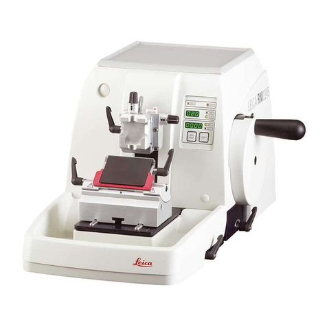
Leica RM2155 User manual

Instruction Manual
Leica RM 2155 V1.1 English 11/2000
Always keep this manual near the instrument
Read carefully prior to operating the instrument
Leica RM 2155
Rotary Microtome


3Leica RM 2155 Rotary Microtome
1. Important information
Serial No. .....................................................................
Year of manufacture: .................................................
Manufactured in: .... Federal Republic of Germany
Leica Microsystems Nussloch GmbH
Heidelberger Str. 17-19
D-69226 Nussloch
Germany
Telephone: 0 62 24 / 143-0
Telefax: 0 62 24 / 1 43-200
eMail: h[email protected]
Homepage: http://www.histo-solutions.com
http://www.materials-sectioning.com
The information, numerical data, notes and value judg-
ments contained in this manual represent the current
state of scientific knowledge and state-of-the-art tech-
nology as we understand it following thorough investi-
gation in this field. We are under no obligation to up-
date the present manual periodically and on an ongo-
ing basis according to the latest technical develop-
ments, nor to provide our customers with additional
copies, updates etc. of this manual.
For erroneous statements, drawings, technical illus-
trations etc. contained in this manual we exclude li-
ability as far as permissible according to the national
legal system applicable in each individual case. In par-
ticular, no liability whatsoever is accepted for any fi-
nancial loss or consequential damage caused by or
related to compliance with statements or other infor-
mation in this manual.
Statements, drawings, illustrations and other informa-
tion as regards contents or technical details of the
present manual are not to be considered as warranted
characteristics of our products. These are determined
only by the contract provisions agreed between our-
selves and our customers.
Leica reserves the right to change technical specifi-
cations as well as manufacturing processes without
prior notice. Only in this way is it possible to continu-
ously improve the technology and manufacturing tech-
niques used in our products.
This document is protected under copyright laws. Any
copyrights of this document are retained by Leica
Microsystems Nussloch GmbH.
Any reproduction of text and illustrations (or of any
parts thereof) by means of print, photocopy, microfiche,
web cam or other methods including any electronic
systems and media requires express prior permis-
sion in writing by Leica Microsystems Nussloch GmbH.
For the instrument serial number and year of manu-
facture, please refer to the name plate at the back of
the instrument.
© Leica Microsystems Nussloch GmbH

4Instruction Manual V1.1 01/2001
2. Table of contents
1. Important information ........................................................................................................................ 3
2. Table of contents ................................................................................................................................ 4
3. Safety instructions for handling the instrument ........................................................................... 5
4. Technical data..................................................................................................................................... 9
5. General description.......................................................................................................................... 11
5.1 Leica RM 2155 - Overview................................................................................................................................11
5.2 General description...........................................................................................................................................12
5.3 Standard delivery ..............................................................................................................................................12
. Unpacking and installation ............................................................................................................ 13
6.1 Unpacking...........................................................................................................................................................13
6.2 Site requirements ..............................................................................................................................................14
7. Setup.................................................................................................................................................... 15
7.1 Mounting the accessories ...............................................................................................................................15
7.2 Connection of foot switch and mains cable ..................................................................................................16
7.3 Connection to mains power .............................................................................................................................17
7.4 Power on.............................................................................................................................................................18
8. Operation ............................................................................................................................................ 19
8.1 Control panel ......................................................................................................................................................19
8.2 Switches and controls ......................................................................................................................................21
9. Orienting specimen clamping system .......................................................................................... 2
9.1 Mounting the specimen clamp........................................................................................................................26
9.2 Orienting the specimen ....................................................................................................................................26
10. Universal knife holder base............................................................................................................ 27
10.1 Repositioning the knife holder base ...............................................................................................................27
10.2 Mounting the knife holder ................................................................................................................................28
10.3 Adjusting the clearance angle ........................................................................................................................28
11. Daily operation .................................................................................................................................. 29
12. Trouble shooting ............................................................................................................................... 30
12.1 Operator and instrument errors ......................................................................................................................30
12.2 Problems, possible causes and corrective action .......................................................................................32
12.3 Instrument errors, possible causes and corrective action ........................................................................33
13. Cleaning ............................................................................................................................................. 35
14. Maintenance...................................................................................................................................... 3
14.1 General maintenance .......................................................................................................................................36
14.2 Changing the setting of the voltage selector ................................................................................................37
14.3 Replacement of the fuses ................................................................................................................................38
15. Accessories ....................................................................................................................................... 39
15.1 Non-orienting specimen clamping system....................................................................................................39
15.2 Specimen clamps ..............................................................................................................................................40
15.3 Knife holder base without lateral displacement ...........................................................................................44
15.4 Mounting the backlighting ...............................................................................................................................44
15.5 Knife holders ......................................................................................................................................................45
15.6 External control panel.......................................................................................................................................50
1 . Ordering information ........................................................................................................................ 51
17. Appendix ............................................................................................................................................ 52
Product changes ...............................................................................................................................................52

Warranty .............................................................................................................................................................52
Disposal...............................................................................................................................................................52
Technical service information.........................................................................................................................52

5Leica RM 2155 Rotary Microtome
3. Safety instructions for handling the instrument
3.1 Safety devices
The instrument incorporates the following safety de-
vices: safety handwheel, emergency-stop switch, pro-
tective guard on the foot switch and knife guard on
the knife holder.
The consistent use of these safety features and strict
observation of the warnings and cautions in this
manual, will safeguard the operator from accidents
and/or personal injury to a great extent.
3.1.1 Emergency-stop switch
The instrument is provided with an emergency stop.
The emergency-stop function is activated with the red
emergency-stop switch on the front of the instrument
(Fig. 5.1) or with the foot switch .
Performance check
Push the emergency-stop switch.
The sectioning motor will stop immediately.
E-STOP (red) on the control panel illuminates indicat-
ing that the emergency-stop function is activated.
To deactivate, turn the red emergency-stop switch
in the direction of the arrow.
E-STOP (red) on the control panel extinguishes.
3.1.2 Foot switch with protective guard
The sectioning motor is started with the foot switch.
The foot switch is provided with a protective guard to
prevent unintended activation.
In addition, the foot switch incorporates a function simi-
lar to the emergency-stop function.
Performance check
Firmly press the foot switch.
The sectioning motor stops immediately upon activa-
tion of the emergency-stop function.
E-STOP (red) on the control panel illuminates as long
as the foot switch is held down.
The safety devices on the instrument and ac-
cessory equipment must not be removed or
modified!
Fig. 5.2
Fig. 5.1

6Instruction Manual V1.1 01/2001
3. Safety instructions for handling the instrument
3.1.4 Safety handwheel
ctivation of the handwheel brake
Always lock the handwheel prior to manipu-
latin the knife and specimen or before chan -
in the specimen or knife!
The handwheel can be locked in any position using the
locking lever (1) on the right side of the microtome base
plate.
Performance check
To activate the brake, pull the locking lever (1) fully
to the front.
The sectioning motor is then electronically and me-
chanically blocked.
LOCK (yellow) on the control panel (Fig. 19) illuminates.
To release the brake, push the locking lever (1) to
the rear.
LOCK extinguishes.
The sectioning motor can then be activated again.
Centering the handle
The handle must always be centered in mo-
torized operation to prevent injury by the re-
volvin handle (Fi . 6.3).
Activate the handwheel brake.
To center, lightly pull the handle (1) out (Fig. 6.2)
and rotate it to the center of the handwheel (Fig.
6.3).
The handle will lock when released.
Knife guard on the knife holder
Prior to manipulatin the knife and specimen,
or chan in the specimen or knife, and dur-
in breaks, always lock cover the cuttin ed e
with the knife uard (1)!
Fig. 6.1
1
1
Fig. 6.3Fig.6.2
Fig. 6.4
1

7Leica RM 2155 Rotary Microtome
3. Safety instructions for handling the instrument
Transport and installation
Please refer to chapter 4 - 'Technical data'!
The instrument must be transported in an
upri ht position!
Do not carry the instrument with the handle
of the handwheel or the control knobs for
sectionin speed and section thickness
settin !
Compare if the settin of the volta e se-
lector at the rear of the instrument com-
plies with the power ratin on the name
plate.
Before connectin to the mains power,
check if the local volta e complies with
these specifications!
Exposure to extreme temperature chan es
and hi h air humidity may cause conden-
sation inside the instrument.
After transportin , please wait at least 2
hours to allow the instrument to adopt the
ambient temperature before turnin it on!
Failure to comply with this may cause dam-
a e to the instrument.
Do not operate in rooms with explosion
hazard!
The safety devices on the instrument and
accessory equipment must not be removed
or modified!
perating the instrument
Take care when handlin microtome
knives and disposable blades. The cuttin
ed e is extremely sharp and can cause
severe injury!
Never leave knives and knife holders with
a mounted knife or blade lyin around! Al-
ways put the knives back into the knife
case when not in use!
Do not place a knife on a table with the
cuttin ed e facin upward!
Never try to catch a fallin knife!
Always clamp the specimen before the
knife!
Prior to manipulatin the knife and speci-
men, or chan in the specimen or knife,
and durin breaks, always lock the hand-
wheel and cover the cuttin ed e with the
knife uard!
Do not attempt to clamp, approach or ori-
ent the specimen in the retraction phase
(while RETRACT illuminates)!
Prior to the subsequent section, a speci-
men advance will take place by the re-
tracted value plus the selected section
thickness.
This involves the risk that the specimen
collides with the knife!
The handle must always be centered in
motorized operation!
Always wear protective lasses when
sectionin brittle specimens!
Risk of splinterin !!
Ensure that liquids do not enter the inte-
rior of the instrument durin work!

8Instruction Manual V1.1 01/2001
3. Safety instructions for handling the instrument
Cleaning
Before cleanin , activate the handwheel
brake, turn the instrument off and pull the
mains plu !
Do not use solvents that contain acetone
and xylene!
Ensure that no liquids enter the interior of
the instrument when cleanin !
When usin deter ents please comply
with the safety precautions of the manu-
facturer.
Do not turn the instrument on before it is
completely dry!
Maintenance
Only authorized and qualified service per-
sonnel may access the internal compo-
nents of the instrument for service and re-
pair!
Turn the instrument off with the mains
switch and pull the mains plu , before re-
placin the fuses!
Only use fuses of the same specification!
For the required values, please refer to
chapter 4 - 'Technical data'.
If the volta e selector is set to an incor-
rect volta e, this can cause severe dam-
a e to the instrument!
Turn the instrument off with the mains
switch and pull the mains plu , before
chan in the volta e settin !

9Leica RM 2155 Rotary Microtome
4. Technical data
Type RM 2155 RM 2155 RM 2155 RM 2155
Submitted for approval - C-UL VDE VDE
Nominal voltage 100 V AC ±10% 120 V AC ±10% 230 V AC ±10% 240 V AC ±10%
Nominal frequency 50/60 Hz 50/60 Hz 50/60 Hz 50/60 Hz
Power draw 340 VA 340 VA 340 VA 340 VA
Protective class I I I I
Mains fuses 2 x T 3.2 A 2 x T 3.2 A 2 x T 3.2 A 2 x T 3.2 A
UL listed UL listed UL listed UL listed
Pollution degree 2222
Overvoltage installation category II II II II
Maximum heat emission 340 J/s 340 J/s 340 J/s 340 J/s
according to IEC-1010, UL 3101, EN 61010
Microtome
Type RM 2155 Rotary microtome
Section thickness setting 0.5 - 60 µm
from 0.5 to 1 µm in 0.5 µm increment
from 1 to 20 µm in 1 µm increments
from 20 to 60 µm in 5 µm increments
Horizontal specimen feed 27 mm
via step motor
Vertical specimen stroke 70 mm
Max. sectioning area without retraction 65 mm without specimen orientation
Max. sectioning area with retraction 60 mm
Specimen retraction
in motorized operation 10, 30, 70 µm, dependent on sectioning speed
can be deactivated
in manual operation 5, 10, 15, 20 µm
can be deactivated
Repositioning of knife holder base
North/south ±25 mm
East/west ±20 mm
Maximum specimen size (W x H x D) 50 x 60 x 40 mm
Specimen orientation
horizontal 8°
vertical 8°
rotation ±90°
Trimming steps 5, 15, 30 µm
Electric coarse feed 900 µm/s
Sectioning motor:
Sectioning speed 0; 0.5 - 420 mm/s
Return speed approx. 120 - 420 mm/s

10 Instruction Manual V1.1 01/2001
4. Technical data
Dimensions and weight
Basic instrument
Width (including handwheel) 400 mm
Width (excluding handwheel) 300 mm
Depth 550 mm
Overall height 290 mm
Working height (knife edge) 100 mm
Net weight 44.2 kg
External control panel (optional accessory)
Width 130 mm
Depth 180 mm
Height 40 mm
Net weight 0.8 kg

11Leica RM 2155 Rotary Microtome
Knife ho der E
for disposab e b ades
Locking ever
for handwhee brake
Knife guard
Cover cap for optiona
i umination, magnifier/
microscope attachment
Section waste tray
C amping ever
for north/south movement
of the knife ho der base
Rocker button for
coarse feed
TRIM STEP setting
Contro knob for
section thickness setting
Handwhee
with centering hand e
Orienting
specimen c amping system
Universa cassette c amp
(UCC)
Contro pane
C amping ever
for
disposab e b ade
TRIM STEP button
C amping ever
for east/west movement
of the knife ho der base
5.1 Leica RM 2155 - verview
Emergency-stop switch
Contro knob
for sectioning speed
Fig. 11.2
Fig. 11.1
Non-orienting
specimen c amping system
(optiona )
Standard specimen c amp
Knife guard
Locking ever
for knife ho der
and c earance ang e setting
5. General description
Hand rest

12 Instruction Manual V1.1 01/2001
5. General description
5.3 Standard delivery
The RM 2155 basic instrument is delivered with the fol-
lowing accessories:
- 1 Orienting specimen clamping system,
- 1 Universal knife holder base with lateral
displacement,
- 1 Section waste tray,
- 1 Foot switch with protective guard,
- 1 Maintenance kit consisting of,
1 Allen key size 8,
1 Allen key size 4,
1 Allen key size 4,
2 Screw drivers,
1 Bottle of oil No. 405, 50 ml,
1 Dust cover,
- 1 Hand rest,
- 1 Set of fuses,
- 1 Mains cable,
- 1 Foot switch adapter,
- 1 Instruction Manual.
You will find these accessories as well as any further
accessories that you may have ordered, in the card-
board box on top of the instrument.
Compare the delivered components with the parts list
and your order. Should you find any discrepancies,
please contact your Leica sales office without delay.
5.2 General description
The Leica RM 2155 is a motorized rotary microtome.
The specimen feed system with zero-backlash and
maintenance-free cross roller guides and the step
motor operated coarse feed system are located in a
dustproof plastic housing. The instrument has a safety
handwheel with centering handle that can be locked
in any position via an electromechanical brake.
Section thickness and sectioning speed are selected
via control knobs. The controls include the TRIM STEP
function with the TRIM STEP button.
The coarse feed is operated with a rocker button.
Specimen retraction is visually indicated and can be
turned off if required. The retraction amount varies with
the sectioning speed.
The control panel is integrated in the front of the mi-
crotome with display, LEDs and function keys for all
important controls is ergonomically positioned at eye
level. All indications are visible at a glance.
Two motorized and one manual sectioning modes are
available. Motorized sectioning is started and stopped
via the foot switch.
The instrument is designed and manufactured to con-
form with the strict UL and VDE safety standards.

13Leica RM 2155 Rotary Microtome
First check the shipment for external dama es
upon arrival.
If is evident that the shipment was dama ed
durin transport, please make a claim to the
carrier immediately.
Cut off the steel bands on the outside of the card-
board box.
Open the cardboard box.
Remove all foam material.
Take out all the accessories (1) and the instruction
manual.
Keep the Allen key size 8 within reach.
Remove the cardboard tray (2).
Remove the cardboard bridge (3).
Take out the instrument by using the carrying
handles (4) which are attached at the front and rear
of the transport platform.
Place the transport platform with the instrument on
a stable table.
Lightly lift the transport platform at the front.
Loosen the screw (6) on the underside of the trans-
port platform with the Allen key size 8 (7) provided
and remove the washer.
Cut off the plastic cover (8) and remove.
Do not carry the instrument with the handle of
the handwheel or the control knobs for sec-
tionin speed and section thickness settin !
To lift the instrument from the transport platform,
hold it at the front of the base plate and at the re-
cessed grip below the heat sink at the rear.
Place the instrument on a stable laboratory table.
Two slide faces (9) located at the rear of the base plate
facilitate to reposition the instrument on the table.
To relocate, lightly lift the instrument at the front of
the base plate and slide it on the slide faces.
. Unpacking and installation
6.1 Unpacking
Fig. 13.1
Fig. 13.2
Fig. 13.3
6
8
7
4
1
2
3
9

14 Instruction Manual V1.1 01/2001
. Unpacking and installation
6.2 Site requirements
Do not operate in rooms with explosion haz-
ard!
To ensure a smooth operation, the instrument
must be set up with at least 10 cm distance
from walls and furniture.
The installation site must meet the following require-
ments:
- stable, vibration-free laboratory table,
- vibration-free floor,
- obstruction-free access to the handwheel,
- Room temperature always between +10 °C and
+ 35 °C,
- relative air humidity must not exceed 80%.

15Leica RM 2155 Rotary Microtome
7. Setup
Fig. 15.3
Fig. 15.1
Fig. 15.2
3
4
6
1
4
3
2
7.1 Mounting the accessories
7.1.1 Mounting the section waste tray
Insert the section waste tray under the microtome
base plate at front.
The plastic rips of all clampin levers can
be repositioned as preferred by the individual
user.
Pull the rip out of the lever, hold it in this po-
sition, and turn it to the desired position. It will
then lock automatically when released.
7.1.2 Mounting the knife holder base
To release, turn the lever (1) counterclockwise.
Place the knife holder base (2) with the two clamp-
ing levers (3) and (4) mounted in place onto the T
piece (5) of the microtome base plate.
To secure the knife holder base, turn the lever (1)
clockwise.
7.1.3 Mounting the hand rest
To release, turn the lever (4) counterclockwise and
the lever (3) clockwise.
Pull both levers out of the knife holder base.
Mount the hand rest (6).
Insert the long lever (3) in the hole on the left and
the short lever (4) in the hole on the right of the hand
rest and lock both levers.
5

16 Instruction Manual V1.1 01/2001
7.2 Connection of foot switch and mains
cable
Connecting the foot switch
Check if the foot switch adapter (1) is present and
if it is properly connected.
Connect the plug of the foot switch to the foot switch
adapter (1) at the rear of the instrument.
Fix the plug by tightening the two screws (2).
The external control panel (optional acces-
sory) can be connected to this socket instead
of the foot switch.
If neither the foot switch nor the external con-
trol panel is connected the instrument will be
inoperational!
Connecting the mains cable
Before connecting the mains cable, check if the
mains switch (3) at the rear of the instrument is in
the OFF position ('O').
Check if the supplied mains cable has the appro-
priate plug.
Connect the mains cable to the socket (4).
Exposure to extreme temperature chan es
and hi h air humidity may cause condensa-
tion inside the instrument.
After transportin , please wait at least 2 hours
to allow the instrument to adopt the ambient
temperature before turnin it on!
Failure to comply with this may cause dam-
a e to the instrument.
7. Setup
34 212
Fig. 16

17Leica RM 2155 Rotary Microtome
7.3 Connection to mains power
Please refer to the technical data!
Before connecting the instrument to the mains,
please check if the local mains voltage complies
with the power rating on the name plate of the in-
strument.
The setting of the voltage selector is visible in the
small window (1) of the voltage selector.
The volta e selector is set to the volta e by
the factory as indicated on the order form. The
name plate reads the power ratin of the volt-
a e selector settin .
A chan e in the settin is enerally not re-
quired.
Should a change be required, however, the voltage
selector has to be set to the voltage available in your
laboratory. Make sure to use the correct fuses for the
setting (see chapter 4 - 'Technical data').
For changing the setting of the voltage selector, please
refer to chapter 14 - 'Maintenance'.
Connect the mains plug to the power outlet at the
wall.
7. Setup
230
1
2
Fig. 17

18 Instruction Manual V1.1 01/2001
7. Setup
7.4 Power on
When turnin the instrument on with the
mains switch, do not press any of the buttons
of control panel, external control panel or the
foot switch!
Turn the instrument on with the mains switch at the
rear.
This is followed by a beep.
The instrument initializes.
The software version is displayed for approx. two sec-
onds.
The display reads the section thickness previously se-
lected (e.g. 0.5 µm).
If the TRIM function is activated the display reads the
TRIM STEP setting previously selected (e.g. 5 µm).
After turning on the LEDs of all activated functions il-
luminate.
If 'LOCK' (yellow) illuminates, release the hand-
wheel brake if activated.

19Leica RM 2155 Rotary Microtome
8. Operation
8.1 Control panel
LED for section thickness, trimming thickness, sec-
tion count, software version, retraction menu (see
'Specimen retraction'), operator errors and error mes-
sages.
µ / n key:
Upper LED -> Section thickness indication (µ)
Lower LED -> Section count indication (n)
Viewing retraction menu and indication of the adjusted
value
CLEAR key
Section counter reset
Viewing/quit the retraction menu
Sectioning mode 1: Single stroke
LED illuminates when activated.
Sectioning mode 2: Continuous stroke
LED illuminates when activated.
LEDs
HOME (green) flashes while the coarse feed but-
ton is held down to move the specimen away from
the knife.
HOME illuminates on reaching the rear limit (HOME
position).
STOP (green) flashes while the coarse feed button
is held down to move the specimen towards the
knife.
STOP illuminates when reaching the remaining feed
point (approx. 1 mm before the actual front limit).
TRIM (yellow) illuminates when the TRIM function
is activated.
E-STOP (red) illuminates when the emergency-stop
is activated.
LOCK (yellow) illuminates when the handwheel is
locked.
MOT (yellow) illuminates while the sectioning mo-
tor is active.
MOT (yellow and green) illuminate during section-
ing before the motor stops in the upper limit.
MOT (green) illuminates when the motor is active.
RETRACT (yellow) illuminates while the specimen
is in the retracted position if the specimen retrac-
tion is activated.
Fig. 19

20 Instruction Manual V1.1 01/2001
Section counter
The display indication can be converted from the sec-
tion or trimming thickness indication to section count.
Push the µ/n button.
The display reading changes from section thickness
to section count and the lower LED illuminates.
Whenever the section thickness setting is changed,
the section count reading will shortly change over to
the section thickness indication.
Section counter reset
Push CLEAR to reset the section counter.
The section count reading is set to 000.
Note:
The section count will be reset by activation of CLEAR
even if the display indicates the section or trimming
thickness.
Selecting the sectioning mode
Two motorized sectioning modes are available: single
stroke and continuous stroke.
Once the required sectioning mode is selected, the LED
next to the button illuminates.
Sectioning mode 1 - Single stroke
To select, push the button.
When sectioning is started with the foot switch, the
specimen head completes a section and stops in the
upper limit automatically.
Sectioning mode 2 - Continuous stroke
To select, push the button.
When sectioning is started with the foot switch, the
specimen head moves until the process is stopped by
activation of the foot switch.
The specimen head will then stop upon reaching the
next upper limit of the stroke.
8. Operation
Table of contents
Other Leica Laboratory Equipment manuals

Leica
Leica RM2125RTS User manual

Leica
Leica HistoCore Arcadia H User manual

Leica
Leica TP1020 User manual

Leica
Leica VT1200 User manual

Leica
Leica PAULA User manual

Leica
Leica BOND-PRIME User manual

Leica
Leica HistoCore MULTICUT User manual

Leica
Leica CryoJane User manual

Leica
Leica Aperio AT2 DX User manual

Leica
Leica Aperio ImageScope DX User manual

Leica
Leica GLOW400 User manual

Leica
Leica HistoCore Arcadia H User manual

Leica
Leica CV5030 User manual

Leica
Leica DFC500 Quick start guide

Leica
Leica RM2235 User manual

Leica
Leica ST5020 User manual

Leica
Leica TCS SP8 User manual

Leica
Leica CM3050 S User manual

Leica
Leica vzM50111 User manual

Leica
Leica GS10 User manual