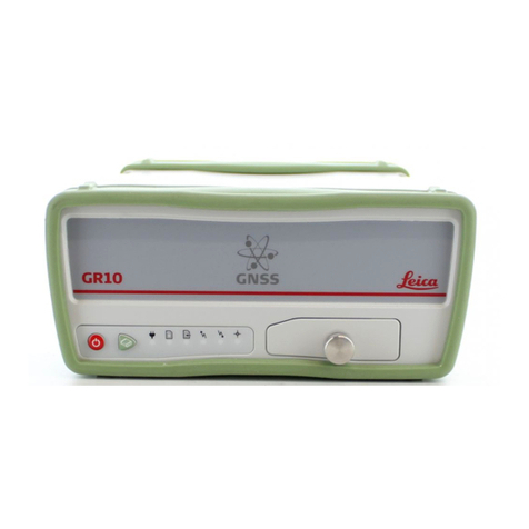
Leica GR10 User manual

Leica GR10
User Manual
Version 1.0
English

2GR10, Introduction
Introduction
Purchase Congratulations on the purchase of a Leica GR10.
This manual contains important safety directions as well as instructions for
setting up the product and operating it. Refer to "6 Safety Directions" for
further information.
Read carefully through the User Manual before you switch on the product.
Product identifica-
tion
The type and serial number of your product are indicated on the type plate.
Enter the type and serial number in your manual and always refer to this infor-
mation when you need to contact your agency or Leica Geosystems authorised
service workshop.
Symbols The symbols used in this manual have the following meanings:
Trademarks • Windows is a registered trademark of Microsoft Corporation in the United
States and other countries.
• SD is a trademark of the SD Card Association
All other trademarks are the property of their respective owners.
Validity of this
manual
This manual applies to the GR10.
Available docu-
mentation
Type: _______________
Serial No.: _______________
Type Description
Danger Indicates an imminently hazardous situation which, if not
avoided, will result in death or serious injury.
Warning Indicates a potentially hazardous situation or an unin-
tended use which, if not avoided, could result in death or
serious injury.
Caution Indicates a potentially hazardous situation or an unin-
tended use which, if not avoided, may result in minor or
moderate injury and/or appreciable material, financial and
environmental damage.
Important paragraphs which must be adhered to in prac-
tice as they enable the product to be used in a technically
correct and efficient manner.
Name Description/Format
GR10 User Manual All instructions required in order to operate
the product to a basic level are contained in
the User Manual. Provides an overview of the
product together with technical data and
safety directions.

GR10, Introduction 3
Refer to the following resources for all GR10 documentation/software:
• the Leica GR10 DVD
• https://myworld.leica-geosystems.com
myWorld@Leica Geosystems (https://myworld.leica-geosystems.com)
offers a wide range of services, information and training material.
With direct access to myWorld, you are able to access all relevant services
whenever it is convenient for you, 24 hours a day, 7 days per week. This
increases your efficiency and keeps you and your equipment instantly updated
with the latest information from Leica Geosystems.
GR10 Operational
Manual (Online
Help)
Comprehensive guide to the product and the
operation. Includes a description of the hard-
ware installation and common accessories.
Software setup is described in detail, along
with the technical specifications.
The complete manual can be viewed online
via the GR10 Web interface.
GNSS Reference
Station and
Networks - An
Introductory Guide
Offers practical advice on how to set up and
run individual GNSS reference stations and
networks of stations and to provide the serv-
ices that are required.
GNSS Networks and
Reference Stations
Equipment List
Detailed list of equipment available for GNSS
reference stations including hardware and
software.
Name Description/Format
Service Description
myProducts Simply add all Leica Geosystems products that you and your
company own. View detailed information on your products,
buy additional options or Customer Care Packages (CCPs),
update your products with the latest software and keep up-to-
date with the latest documentation.
myService View the service history of your products in Leica Geosystems
Service Centers and detailed information on the services
performed on your products. For your products that are
currently in Leica Geosystems Service Centers view the current
service status and the expected end date of service.
mySupport Create new support requests for your products that will be
answered by your local Leica Geosystems Support Team. View
the complete history of your Support and view detailed infor-
mation on each request in case you want to refer to previous
support requests.
myTraining Enhance your product knowledge with the Leica Geosystems
Campus - Information, Knowledge, Training. Study the latest
online training material or download training material on your
products. Keep up-to-date with the latest News on your prod-
ucts and register for Seminars or Courses in your country.

4GR10, Table of Contents
Table of Contents
In this manual Chapter Page
1 Description of the System 6
1.1 GR10 General Information 6
1.2 GNSS Reference Station Components 7
1.3 Unpacking the GR10 instrument 9
1.4 Instrument Components 9
1.5 GR10 Operation 10
1.6 GR10 Software 12
1.7 Power Supply 13
2 Installation 14
2.1 Before Installation 14
2.2 Installation Options 15
3 User Interface 18
3.1 LED Indicators on GR10 18
3.2 Keyboard 20
3.3 USB and SD Card Cover 23
4 Operation 24
4.1 Equipment Setup 24
4.1.1 Basic Setup 24
4.1.2 Setup via Web Interface over Ethernet and DHCP 25
4.1.3 Install USB drivers 26
4.2 Working with the Memory Device 32
4.3 Working with Radio, Modem and GSM Devices 34
4.3.1 Serial Devices 34
4.3.2 Slot-in Devices 37
5 Care and Transport 40
5.1 Transport 40
5.2 Storage 40
5.3 Cleaning and Drying 40
6 Safety Directions 41
6.1 General Introduction 41
6.2 Intended Use 41
6.3 Limits of Use 41
6.4 Responsibilities 42
6.5 Hazards of Use 42
6.6 Electromagnetic Compatibility EMC 45
6.7 FCC Statement, Applicable in U.S. 47

GR10, Table of Contents 5
7 Technical Data 48
7.1 GR10 Technical Data 48
7.1.1 Tracking Characteristics 48
7.1.2 Accuracy 49
7.1.3 Technical Data 50
7.2 Antennas Technical Data 52
7.3 Conformity to National Regulations 54
7.3.1 GR10 54
7.3.2 GFU24, Siemens MC75 55
7.3.3 GFU19 (US), GFU25 (CAN) CDMA MultiTech
MTMMC-C 56
7.3.4 SLG1-2, Telit 3G GSM/GPRS/UMTS 56
7.3.5 SLR1-2, SATEL SATELLINE-TA11 57
8 International Limited Warranty, Software Licence Agreement 59
Appendix A Directory Structure of the Memory Device 60
Appendix B GR10 Pin Assignments and Sockets 61
Index 62

6 GR10, Description of the System
1 Description of the System
1.1 GR10 General Information
Design The GR10
• is designed for various permanent and semi-permanent reference station
applications, including network RTK, single base station, scientific,
campaign, monitoring and seismic studies.
• collects, stores and disseminates GNSS data.
• is highly suited to system integration.
• supports various external devices including communication, meteo and tilt.
Satellite tracking The GR10 can track
• GPS L1/L2 (including L2C)/L5
• GLONASS L1/L2
• Galileo E1/E5a/E5b/AltBOC
•SBAS
Once the first operational Galileo satellites are available, a software update will
be required.
The GR10 instrument is designed to support Compass. The Compass signal defi-
nition is not fully finalised, although, test signals have been tracked in a test
environment. As changes may still occur, Leica Geosystems cannot guarantee
full Compass compatibility.
Special features The instruments are equipped with several special features:
• 50 Hz data logging and streaming.
• SmartTrack+ measurement engine for higher accuracy and availability.
• Up to 10 multiple logging sessions and 20 data streams.
• Multiple data storage formats including MDB, RINEX and Hatanaka.
• Supports high capacity storage up to 32 GB and intelligent Smart clean-up.
• Multiple data output formats including Leica, Leica 4G, RTCM 2.x,3.x, LB2,
BINEX, CMR, CMR+.
• Modern, user friendly Web interface GUI, available in different languages.
• Seamless integration with Leica GNSS Spider.
• Robust lightweight metal housing.
• Fully ruggedised to IP67, including a ruggedised Ethernet port.
• Simple mounting for IT rack, cabinet and wall mount. Unit is also stackable.
• Built in communications Slot-in port.
• Integrated device management for external devices.
• Supports DHCP, DNS, DynDNS and mobile internet.
• Improved security including IP filtering, access management and HTTPS with
SSL.
• Out of the box plug and play hostname setup.
• Wide supply voltage 10.5-28 V.
• Low-power consumption, with 3.0-3.5 W typical.

GR10, Description of the System 7
1.2 GNSS Reference Station Components
Component over-
view
The following diagram shows a typical reference station setup and the most
common accessories that can be used with a GR10.
a) Radio/GSM antenna
b) Antenna bracket
c) Antenna cable
d) GFU housing incl. Radio/GSM
device
e) Meteo sensor
f) Tilt sensor
g) Serial cable
h) SD card
i) Optional radome for AR25
j) GNSS antenna, AR10
k) GNSS antenna, AR25
l) GNSS antenna, AS10
m) Antenna cable
n) Optional lightning protection
o) Ethernet hub
p) Computer running GNSS Spider or
web interface
q) Ethernet cable
r) GR10
s) Slot-in radio/GSM device
t) Antenna cable
u) Power supply
v) Oscillator cable
w) External oscillator
p
a
efg
b
d
c
j
k
l
i
a
b
t
o
q
r
s
u
v
w
mn
h
GR10_004

8 GR10, Description of the System
Minimum setup
components
The following diagram shows the minimum components required to operate a
GR10.
Main components
a) SD card*
b) Antenna cable
c) GNSS Antenna
d) Computer running Web interface or Leica GNSS Spider
e) Ethernet or USB cable
f) GR10
g) Power supply
*The GR10 can be operated without the SD card but only data streaming will
be possible.
a
e
d
f
g
b
c
GR10_021
Component Description
GR10 To provide the storage and streaming of raw satellite
data.
Antenna To receive the satellite signals from the GNSS (Global
Navigation Satellite System) satellites
Web interface Web-based tool to configure the GR10.
Leica GNSS Spider The reference station office software including compre-
hensive instrument control and configuration, file down-
load and firmware upload functions which support
working with Leica GR10 instruments. Supports the
connection to single or multiple reference instruments
simultaneously.

GR10, Description of the System 9
1.3 Unpacking the GR10 instrument
Delivery box for
GR10
The minimum items delivered with the GR10 include:
Accessories Additional equipment such as cables, antennas and power supply required for
a complete reference station installation are delivered with the GR10 when
ordered. For an overview of a typical reference station installation and the
accessories that can be used with the GR10 go to "Component overview".
For further information on accessories, please refer to the "GR10 Operational
Manual (Online Help)".
1.4 Instrument Components
GR10 components
a) GR10
b) DVD
c) GR10 User Manual
GR10_022
abc
DVD
a) User interface
b) USB and SD card cover
c) Front rubber bumper
d) Back rubber bumper
e) GNSS Antenna port
f) External Oscillator port
g) Serial port (P1)
h) Ruggedised Ethernet port
i) Power port
j) Communication Slot-in port Antenna (P3)
k) Communication Slot-in port (P3)
GR10_001 abc d e f g h i j
k

10 GR10, Description of the System
1.5 GR10 Operation
GR10 operation The GR10 instrument can be operated by:
• pressing its buttons (ON/OFF button, Function button)
• the GR10 Web interface
• Leica GNSS Spider software
• or with the Leica Binary 2 (LB2) interface. Contact your Leica Geosystems
representative for information on LB2 documentation.
The GR10 instrument is delivered with default settings which cover the
needs of the typical user. Use the Web interface or Leica GNSS Spider
to adjust the GR10 settings.
Operation by Web
interface
The Web interface is the main component used to configure and operate the
GR10.
Refer to the "GR10 Operational Manual (Online Help)" for a detailed description
of the Web Interface.
Supported operating systems for Web interface setup over USB
• Windows XP Professional SP2 and SP3 (32 bit)
• Windows Vista Enterprise SP2 (32 bit)
• Windows Server 2008 SP1 (64 bit)
• Windows 7 Ultimate (32 bit and 64 bit)
Supported web browsers for the GR10 Web interface
The Web interface is the primary interface between the user and the
GR10. To use the Web interface correctly make sure the web browser
allows JavaScript to be run. Check the web browsers settings if you have
problems using the Web interface.
Web interface
security
When accessing the Web interface for the first time use the default User name
(Admin) and Password (12345678).
For security reasons, it is recommended to create a new administrator
account when logging in for the first time. After creating the new
administrator, log out and relogin with the new user credentials. The
default user account can then be deleted. Refer to the "GR10 Opera-
tional Manual (Online Help)" for a step-by-step guide.
Web browser Supported version
Internet Explorer 7 and higher
Firefox 3.5 and higher
Opera 10 and higher
Safari 4 and higher
Google Chrome 4 and higher

GR10, Description of the System 11
Operation by Leica
GNSS Spider
The reference station software Leica GNSS Spider provides comprehensive
instrument functionality, like the Web interface.
Some configuration settings are available both in the Web interface and
in Leica GNSS Spider. If such settings are configured in the Web inter-
face, and then an Upload Settings or Start is done from Leica GNSS
Spider, the settings are overwritten. In this case use the Web interface
exclusively for settings that are not available in Leica GNSS Spider.
To operate Leica GNSS Spider, refer to the
• "GR10 Operational Manual (Online Help)" for basic information.
• "Leica GNSS Spider Online Help" for advanced information.
Requirement
• GR10: Leica GNSS Spider v4.0 or later must be installed.
GNSS Spider
features
GNSS Spider features:
• Simultaneous configuration and communication with one or many instru-
ments.
• Monitoring and messaging on instrument key parameters such as power
voltage level, data storage availability, instruments internal temperature or
events logged on the instrument.
• Visualisation of satellite tracking status.
• Transfer of raw data automatically from the instrument to a central data
storage.
• Perform RINEX conversion manually or automatically at different decimation
rates and file lengths.
• FTP push archived data to multiple locations.
• Perform automatic quality control of archived RINEX data.
• Manage an entire network of reference stations.
• Supply single base or network RTK corrections to many users using various
communication methods, including for example, Ntrip .
• Protect and manage access to RTK correction services using the Spider Busi-
ness Center advanced user access management.

12 GR10, Description of the System
1.6 GR10 Software
Software for GR10
Software upload
Software type Description
GR firmware
(GR10_x.xx.fw)
The GR10 firmware is called RefWorx.
This important system software covers the basic
functions of the instrument.
The onboard Web interface is integrated into the
firmware and cannot be deleted.
The English language is integrated into the firmware
and cannot be deleted.
Language software
(REF_LANG.sxx)
Numerous languages are available for the instrument
web server. Language software is also referred to as
system language.
The system software enables a maximum of three
languages which can be stored at any one time - the
English language and two other languages. The
English language is the default language and cannot
be deleted. One language is chosen as the active
language.
Windows CE
Operating System
(GR10_WinCE_x.x.xx.fw)
Windows CE is the underlying operating system on
the GR10.
Measurement Engine
firmware
(ME4.xx.fw)
This file contains the Measurement Engine firmware
for the GR10. This firmware is always included in the
GR10 firmware file. If an update becomes available
the file can be loaded separately onto the GR10.
Software for Description
GR10 All software is stored in the System RAM of the
instrument.
A new firmware file must be uploaded to the SD card
before installation. The file can be uploaded via:
• the GR10 Web interface.
• direct copy to the SD card using a computer.
• direct FTP access to the SD card.
After uploading, the firmware must be transferred
from the SD card to the System RAM via the GR10
Web interface. Refer to the "GR10 Operational
Manual (Online Help)" for further information.
Leica GNSS Spider can also be used to install the
firmware. Loading the firmware to the SD card and
installing it on the instrument is done in one step
when using GNSS Spider. Refer to the "Leica GNSS
Spider Online Help" for more information.

GR10, Description of the System 13
1.7 Power Supply
General Use the Leica Geosystems power supplies, batteries, chargers and accessories
or accessories recommended by Leica Geosystems to ensure the correct func-
tionality of the instrument.
Power options Power for the instrument can be supplied either by power supply or batteries.
Up to two external power supplies can be connected using a Y-cable.
For permanent operations use Uninterruptible Power Supply units as a back-up
in a main power failure.
External power supply: GEV242 (774437), 110 V/240 V AC to 24 V DC power
supply unit, supplied by Leica Geosystems.
OR
110 V/240 V AC to 12 V DC power supply unit
(722409), supplied by Leica Geosystems.
OR
GEB171 (439038) battery connected via a cable.
OR
Car battery connected via a converter cable supplied
by Leica Geosystems.
Y-cable: GEV243 (774438), Y-cable can be used with GEV242
power supply and GEB171 battery or the existing 12 V
power supply (722409). The black Lemo connector on
this cable only supports the use of the GEV242 power
supply.
OR
GEV172 (733298), Y-cable can be used with any
combination of 110 V/240 V AC to 12 V DC power
supply (722409) or a GEB171 battery.

14 GR10, Installation
2 Installation
2.1 Before Installation
Installation loca-
tion
It is recommended that the instrument is installed so that it is
• protected from mechanical influences and lightning
• within 70 m of the antenna, without the need to use inline amplifiers.
Installation orien-
tation
• For inside assembly, the instrument can be installed in any direction
• When installing the instrument outside, orientate the instrument vertically
so that the connector points are pointing downwards
Cable installation Ensure that the cables between the instrument and antenna are positioned to
prevent them from becoming bent, stretched or squeezed. For the installation
of the cables, the general rules for the installation of electrical wiring apply.
Please consider that a well-planned and thoroughly carried out electric installa-
tion not only protects the cables against damage, but also looks professional.
For detailed installation information, refer to the "GNSS Reference Station and
Networks - An Introductory Guide".

GR10, Installation 15
2.2 Installation Options
Description GR10 instruments are designed for various installation cases. Below is a short
description of four installation cases for the GR10. Please note that the
diagrams do not show all the equipment required for a complete reference
station installation. For full installation details, please refer to the
• GNSS Reference Station and Networks - An Introductory Guide.
• GNSS Networks and Reference Stations Equipment List
Rack Mount Together with the rack mount accessory kit the GR10 can be easily mounted
into a standard 19 inch IT rack.
If space in the rack is limited, then the rubber bumpers on the GR10 can
be removed. The total height of the rack kit and instrument is then 2U.
If the bumpers are removed, please remove the small feet from the
mounting brackets.
The radio/GSM antenna must be installed on the outside of the rack if
a slot-in or serial device is used.
a) Radio/GSM antenna
b) Antenna bracket
c) Radio/ GSM antenna
cable
d) Rack mount kit
e) GR10
f) Rack mount kit
GR10_016
a
b
c
d
e
f

16 GR10, Installation
Wall / Cabinet
Mount
Together with the wall mount accessory kit the GR10 can be easily mounted
onto an existing wall or structure, or inside an environmental case.
If space in the cabinet is limited, then the rubber bumpers on the GR10
can be removed. If the bumpers are removed, please remove the small
feet from the mounting brackets.
The radio/GSM antenna must be installed on the outside of the rack if
a slot-in or serial device is used.
Free Standing /
Stacking
The GR10 is designed to allow stable free standing installation and stacking for
easy configuration of multiple receivers.
When stacking multiple GR10 instruments on top of each other, the
rubber bumpers must be on.
a) Radio/GSM antenna
b) Antenna bracket
c) Radio/GSM antenna
cable
d) Wall mount kit -
feet
e) Wall mount kit -
bracket
f) Rubber bumper
GR10_017
a
b
d
c
e
f
GR10_018

GR10, Installation 17
Tripod The GR10 has a built-in Tripod mount to allow attachment to all Leica Geosys-
tems Tripods.
When using the GR10 on a tripod, the rubber bumpers must be on.
a) AS10
b) GNSS antenna carrier with
5/8 inch screw
c) Tribrach
d) Tripod
e) Antenna cable
f) GR10
GR10_019
a
b
c
de
f

18 GR10, User Interface
3 User Interface
3.1 LED Indicators on GR10
LED indicators Description
The GR10 has Light Emitting Diode indicators. They indicate the basic instru-
ment status.
Diagram
Description of the
LED’s
a) Power LED
b) SD card LED
c) Raw data logging LED
d) RT out data stream LED
e) RT in data stream LED
f) Position LED
GR10_003
a b c d e f
IF the is THEN
Power LED off External power is not connected or power is off
green The power level of the connected power source
is between 40-100%.
yellow The power level of the connected power source
is between 10-40%.
The LED indicates the overall power status. If a
second external power source is connected
using a Y-cable, both power sources are used
simultaneously. When the LED is yellow, the
power level on both external power sources is
low, 10-40%.
red The power level of the connected power source
is between 1-10%.
Recommended user action: Switch to
a new power source.
SD card LED off No SD card inserted or power is off.
green SD card is inserted. The free space on the SD
card is greater than 20%.
yellow The free space on the SD card is below 20%.
Recommended user action: Activate
the Smart clean-up or the automatic file
delete for each logging session.
red SD card is full. Data logging has stopped.
Recommended user action: Immedi-
ately activate the Smart clean-up or the
automatic file delete for each logging
session.

GR10, User Interface 19
Raw data
logging LED
off No active logging sessions or power is off.
green Active logging sessions are configured on the
instrument and data is being logged
yellow Active logging sessions are configured but Smart
clean-up is deleting data from all or some of the
configured logging sessions.
Recommended user action: Check the
remaining space of the SD card and
delete old data if necessary.
red Active logging sessions are configured but the
SD card is full or no navigated position is avail-
able.
Recommended user action: Check the
SD card and the tracking status.
RT out data
stream LED
off No active data stream is configured or power is
off.
green One or more data streams are configured and
active. Data is being streamed.
red Data streams are active but no data is streamed.
Recommended user action: Check
that data is tracked and a navigated
position is available. Check that the
correct reference position is entered.
RT in data
stream LED
- Currently not supported.
Position LED off The instrument is switched off.
flashing
green
The instrument is tracking satellites but no posi-
tion is available.
green A navigated position is available.
red No satellites are tracked and no navigated posi-
tion is available.
IF the is THEN

20 GR10, User Interface
3.2 Keyboard
GR10 Keyboard
The instrument can be turned on and off by holding down the ON/OFF
button for 2 s. A green steady light at the power LED indicates that the
instrument is turned on and ready.
ON/OFF button
Hold the ON/OFF button for 10 s, to force the instrument to turn off.
Instrument settings and some data can be lost when using this method.
Function button All the following functions described assume the GR10 is already on.
Button combina-
tions
a) ON/OFF button
b) Function button
c) LED’s
GR10_002
ab c
Button Function
ON/OFF If GR10 already off: Turns on GR10 when held for 2 s.
If GR10 already on: Turns off GR10 when held for 2 s.
Button Function
Function The Function and ON/OFF button work in combination
and allow a number different functions as described in
"Button combinations".
The Function button switches between these different
functions.
Buttons How to
+2sActivate dual button functionality
Press and hold both buttons for 2 s until all LEDs are
flashing. After 1 s, the Raw data logging LED starts
flashing.
The following instrument commands are now activated.
Start/Stop all logging sessions
Activate the dual button functionality.
If all logging sessions had been off, the Raw data logging
LED is flashing green.
Other manuals for GR10
3
Table of contents
Other Leica Receiver manuals

Leica
Leica GS15 User manual

Leica
Leica GM30 User manual

Leica
Leica GR30 Reference guide

Leica
Leica Viva GNSS User manual

Leica
Leica GS14 User manual

Leica
Leica GMX902 GG User manual

Leica
Leica GR10 Quick start guide

Leica
Leica GS16 User manual

Leica
Leica GPS1200 Series User manual

Leica
Leica GGo4 Instruction Manual

Leica
Leica GPS900 Series Product manual

Leica
Leica GS14 User manual

Leica
Leica iCON gps 60 Manual

Leica
Leica iCON gps 70 User manual

Leica
Leica GS18 User manual

Leica
Leica RVL100 User manual

Leica
Leica GRX1200 series User manual

Leica
Leica Zeno 10 User manual

Leica
Leica TPS400 Series User manual

Leica
Leica Zeno 20 3.75G Android User manual