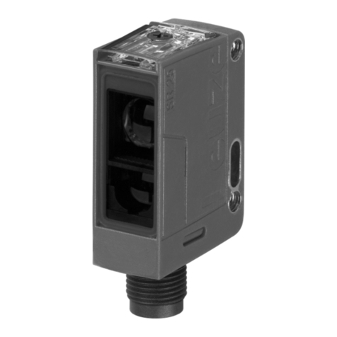
Leuze BPS 8 SM 102 User manual

BPS 8
Bar Code Positioning System
Original operating instructions
EN • 2020-10-20 • 50105556
We reserve the right to make technical changes

Leuze electronic GmbH + Co. KG BPS 8 2
© 2020
Leuze electronic GmbH & Co. KG
In der Braike 1
D-73277 Owen / Germany
Phone: +49 7021 573-0
Fax: +49 7021 573-199
http://www.leuze.com

Leuze electronic GmbH + Co. KG BPS 8 3
1 About this document . . . . . . . . . . . . . . . . . . . . . . . . . . . . . . . . . . . . . . . . . . . . . . 6
1.1 Used symbols and signal words . . . . . . . . . . . . . . . . . . . . . . . . . . . . . . . . . . . . . . . . . . . . . 6
2 Safety . . . . . . . . . . . . . . . . . . . . . . . . . . . . . . . . . . . . . . . . . . . . . . . . . . . . . . . . . . 7
2.1 Intended use . . . . . . . . . . . . . . . . . . . . . . . . . . . . . . . . . . . . . . . . . . . . . . . . . . . . . . . . . . . . 7
2.2 Foreseeable misuse . . . . . . . . . . . . . . . . . . . . . . . . . . . . . . . . . . . . . . . . . . . . . . . . . . . . . . 8
2.3 Competent persons . . . . . . . . . . . . . . . . . . . . . . . . . . . . . . . . . . . . . . . . . . . . . . . . . . . . . . . 8
2.4 Exemption of liability . . . . . . . . . . . . . . . . . . . . . . . . . . . . . . . . . . . . . . . . . . . . . . . . . . . . . . 8
2.5 Laser safety notices. . . . . . . . . . . . . . . . . . . . . . . . . . . . . . . . . . . . . . . . . . . . . . . . . . . . . . . 9
3 Technical data of BPS 8. . . . . . . . . . . . . . . . . . . . . . . . . . . . . . . . . . . . . . . . . . . 11
3.1 General specifications BPS 8 . . . . . . . . . . . . . . . . . . . . . . . . . . . . . . . . . . . . . . . . . . . . . . 11
3.2 Dimensioned drawings . . . . . . . . . . . . . . . . . . . . . . . . . . . . . . . . . . . . . . . . . . . . . . . . . . . 13
3.3 Reading field curves . . . . . . . . . . . . . . . . . . . . . . . . . . . . . . . . . . . . . . . . . . . . . . . . . . . . . 15
4 MA 8… / MA 2xxi connection units . . . . . . . . . . . . . . . . . . . . . . . . . . . . . . . . . . 16
4.1 MA 8.1 connection unit . . . . . . . . . . . . . . . . . . . . . . . . . . . . . . . . . . . . . . . . . . . . . . . . . . . 16
4.2 MA 8-01 / MA 8-02 connection unit . . . . . . . . . . . . . . . . . . . . . . . . . . . . . . . . . . . . . . . . . . 17
4.3 MA 2xxi connection unit. . . . . . . . . . . . . . . . . . . . . . . . . . . . . . . . . . . . . . . . . . . . . . . . . . . 17
5 Bar code tape. . . . . . . . . . . . . . . . . . . . . . . . . . . . . . . . . . . . . . . . . . . . . . . . . . . 18
5.1 General information . . . . . . . . . . . . . . . . . . . . . . . . . . . . . . . . . . . . . . . . . . . . . . . . . . . . . . 18
5.2 BCB G30 ... control bar code MVS . . . . . . . . . . . . . . . . . . . . . . . . . . . . . . . . . . . . . . . . . . 19
5.3 Marker bar codes. . . . . . . . . . . . . . . . . . . . . . . . . . . . . . . . . . . . . . . . . . . . . . . . . . . . . . . . 22
5.4 Technical data of the BCB G30 ... bar code tape . . . . . . . . . . . . . . . . . . . . . . . . . . . . . . . 24
5.5 Dimensioned drawing for position, control and marker bar codes. . . . . . . . . . . . . . . . . . . 25
6 Mounting and installation . . . . . . . . . . . . . . . . . . . . . . . . . . . . . . . . . . . . . . . . . . 26
6.1 Mounting the bar code tape. . . . . . . . . . . . . . . . . . . . . . . . . . . . . . . . . . . . . . . . . . . . . . . . 26
6.1.1 Installation and application remarks . . . . . . . . . . . . . . . . . . . . . . . . . . . . . . . . . . . . . . . 26
6.1.2 Cutting bar code tapes . . . . . . . . . . . . . . . . . . . . . . . . . . . . . . . . . . . . . . . . . . . . . . . . . 27
6.1.3 Mounting the BCB . . . . . . . . . . . . . . . . . . . . . . . . . . . . . . . . . . . . . . . . . . . . . . . . . . . . . 28
6.1.4 BCB repair with repair kit. . . . . . . . . . . . . . . . . . . . . . . . . . . . . . . . . . . . . . . . . . . . . . . . 30
6.2 Mounting the BPS 8. . . . . . . . . . . . . . . . . . . . . . . . . . . . . . . . . . . . . . . . . . . . . . . . . . . . . . 32
6.2.1 BT 8-01 mounting device . . . . . . . . . . . . . . . . . . . . . . . . . . . . . . . . . . . . . . . . . . . . . . . 33
6.2.2 BT 8-0 mounting device . . . . . . . . . . . . . . . . . . . . . . . . . . . . . . . . . . . . . . . . . . . . . . . . 33
6.3 Device arrangement . . . . . . . . . . . . . . . . . . . . . . . . . . . . . . . . . . . . . . . . . . . . . . . . . . . . . 35
7 Electrical connection . . . . . . . . . . . . . . . . . . . . . . . . . . . . . . . . . . . . . . . . . . . . . 38
7.1 Safety notices for the electrical connection . . . . . . . . . . . . . . . . . . . . . . . . . . . . . . . . . . . . 38
7.2 Electrical connection BPS 8 . . . . . . . . . . . . . . . . . . . . . . . . . . . . . . . . . . . . . . . . . . . . . . . 38
7.2.1 BPS 8 - PWR IN - Voltage supply, RS 232, Switching input/output . . . . . . . . . . . . . . . 38
7.3 Electrical connection via connection unit MA 8.1 . . . . . . . . . . . . . . . . . . . . . . . . . . . . . . . 40
7.3.1 Electrical connection MA 8.1 . . . . . . . . . . . . . . . . . . . . . . . . . . . . . . . . . . . . . . . . . . . . . 40
7.3.2 PWR IN HOST/RS 232 connector – voltage supply and RS 232 . . . . . . . . . . . . . . . . . 40
7.3.3 SW IN/OUT socket – switching input and switching output . . . . . . . . . . . . . . . . . . . . . . 41
7.3.4 BCL socket – connecting the BPS 8 to the MA 8.1 . . . . . . . . . . . . . . . . . . . . . . . . . . . . 42
7.4 Electrical connection via connection unit MA 8-01 / MA 8-02 . . . . . . . . . . . . . . . . . . . . . . 43
7.4.1 PWR IN HOST/RS485 connector – voltage supply/RS 485 . . . . . . . . . . . . . . . . . . . . . 43
7.4.2 SW IN/OUT socket – switching input and switching output . . . . . . . . . . . . . . . . . . . . . . 43
7.4.3 BCL/BPS socket – connecting the BPS 8 to the MA 8-01/MA 8-02 . . . . . . . . . . . . . . . 44
7.4.4 Termination of the RS 485 interface . . . . . . . . . . . . . . . . . . . . . . . . . . . . . . . . . . . . . . . 45

Leuze electronic GmbH + Co. KG BPS 8 4
8 Configuration / device parameters . . . . . . . . . . . . . . . . . . . . . . . . . . . . . . . . . . . 46
8.1 RS 232/RS 485 interface. . . . . . . . . . . . . . . . . . . . . . . . . . . . . . . . . . . . . . . . . . . . . . . . . . 46
8.1.1 General information. . . . . . . . . . . . . . . . . . . . . . . . . . . . . . . . . . . . . . . . . . . . . . . . . . . . 46
8.2 BPS Configuration Tool software . . . . . . . . . . . . . . . . . . . . . . . . . . . . . . . . . . . . . . . . . . . 46
8.2.1 Installation of the BPS Configuration Tool software . . . . . . . . . . . . . . . . . . . . . . . . . . . 46
8.2.2 Brief manual for the BPS Configuration Tool . . . . . . . . . . . . . . . . . . . . . . . . . . . . . . . . 47
8.2.3 Setting the parameters . . . . . . . . . . . . . . . . . . . . . . . . . . . . . . . . . . . . . . . . . . . . . . . . . 50
8.3 Service operating mode. . . . . . . . . . . . . . . . . . . . . . . . . . . . . . . . . . . . . . . . . . . . . . . . . . . 50
8.3.1 Activate service interface . . . . . . . . . . . . . . . . . . . . . . . . . . . . . . . . . . . . . . . . . . . . . . . 50
8.3.2 Connecting the service interface . . . . . . . . . . . . . . . . . . . . . . . . . . . . . . . . . . . . . . . . . . 51
8.3.3 Overview of commands and parameters. . . . . . . . . . . . . . . . . . . . . . . . . . . . . . . . . . . . 51
8.4 Overview of the parameter structure . . . . . . . . . . . . . . . . . . . . . . . . . . . . . . . . . . . . . . . . . 52
8.5 Detailed description of the tabs . . . . . . . . . . . . . . . . . . . . . . . . . . . . . . . . . . . . . . . . . . . . . 53
8.5.1 Control. . . . . . . . . . . . . . . . . . . . . . . . . . . . . . . . . . . . . . . . . . . . . . . . . . . . . . . . . . . . . . 53
8.5.2 Position detection . . . . . . . . . . . . . . . . . . . . . . . . . . . . . . . . . . . . . . . . . . . . . . . . . . . . . 54
8.5.3 Communication . . . . . . . . . . . . . . . . . . . . . . . . . . . . . . . . . . . . . . . . . . . . . . . . . . . . . . . 58
8.5.4 Switching input . . . . . . . . . . . . . . . . . . . . . . . . . . . . . . . . . . . . . . . . . . . . . . . . . . . . . . . 59
8.5.5 Switching output . . . . . . . . . . . . . . . . . . . . . . . . . . . . . . . . . . . . . . . . . . . . . . . . . . . . . . 60
9 Protocols for position value output . . . . . . . . . . . . . . . . . . . . . . . . . . . . . . . . . . . 62
9.1 Binary protocol 1 – BPS 8 SM 10x-01 / BPS 8 SM 10x-05 . . . . . . . . . . . . . . . . . . . . . . . . 62
9.1.1 Data format . . . . . . . . . . . . . . . . . . . . . . . . . . . . . . . . . . . . . . . . . . . . . . . . . . . . . . . . . . 62
9.1.2 Request telegram to the BPS 8 SM 10x-01 / BPS 8 SM 10x-05. . . . . . . . . . . . . . . . . . 62
9.1.3 BPS 8 SM 10x-01 / BPS 8 SM 10x-05 response telegram . . . . . . . . . . . . . . . . . . . . . . 63
9.2 Binary protocol 2 – BPS 8 SM 10x-02 . . . . . . . . . . . . . . . . . . . . . . . . . . . . . . . . . . . . . . . . 68
9.2.1 Data format . . . . . . . . . . . . . . . . . . . . . . . . . . . . . . . . . . . . . . . . . . . . . . . . . . . . . . . . . . 68
9.2.2 Request telegram to the BPS 8 SM 10x-02 . . . . . . . . . . . . . . . . . . . . . . . . . . . . . . . . . 69
9.2.3 BPS 8 SM 10x-02 response telegram . . . . . . . . . . . . . . . . . . . . . . . . . . . . . . . . . . . . . . 70
9.3 Binary protocol 3 – BPS 8 SM 10x-03 . . . . . . . . . . . . . . . . . . . . . . . . . . . . . . . . . . . . . . . . 74
9.3.1 Data format . . . . . . . . . . . . . . . . . . . . . . . . . . . . . . . . . . . . . . . . . . . . . . . . . . . . . . . . . . 74
9.3.2 Request telegram to the BPS 8 SM 10x-03 . . . . . . . . . . . . . . . . . . . . . . . . . . . . . . . . . 74
9.3.3 BPS 8 SM 10x-03 response telegram . . . . . . . . . . . . . . . . . . . . . . . . . . . . . . . . . . . . . . 75
9.4 Binary protocol 4 – BPS 8 SM 10x-04 . . . . . . . . . . . . . . . . . . . . . . . . . . . . . . . . . . . . . . . . 77
9.4.1 Data format . . . . . . . . . . . . . . . . . . . . . . . . . . . . . . . . . . . . . . . . . . . . . . . . . . . . . . . . . . 77
9.4.2 Request telegram to the BPS 8 SM 10x-04 . . . . . . . . . . . . . . . . . . . . . . . . . . . . . . . . . 77
9.4.3 BPS 8 SM 10x-04 response telegram . . . . . . . . . . . . . . . . . . . . . . . . . . . . . . . . . . . . . . 79
9.4.4 Binary protocol 4 request sequences . . . . . . . . . . . . . . . . . . . . . . . . . . . . . . . . . . . . . . 81
9.5 Binary protocol 6 – BPS 8 SM 10x-10 . . . . . . . . . . . . . . . . . . . . . . . . . . . . . . . . . . . . . . . . 81
9.5.1 Data format . . . . . . . . . . . . . . . . . . . . . . . . . . . . . . . . . . . . . . . . . . . . . . . . . . . . . . . . . . 82
9.5.2 Request telegram to the BPS 8 SM 10x-10 . . . . . . . . . . . . . . . . . . . . . . . . . . . . . . . . . 82
9.5.3 BPS 8 SM 10x-10 response telegram . . . . . . . . . . . . . . . . . . . . . . . . . . . . . . . . . . . . . . 83
10 Diagnostics and troubleshooting . . . . . . . . . . . . . . . . . . . . . . . . . . . . . . . . . . . . 85
10.1 Operating indicators of the LEDs. . . . . . . . . . . . . . . . . . . . . . . . . . . . . . . . . . . . . . . . . . . . 85
10.2 General causes of errors . . . . . . . . . . . . . . . . . . . . . . . . . . . . . . . . . . . . . . . . . . . . . . . . . . 85
10.3 Error on the interface. . . . . . . . . . . . . . . . . . . . . . . . . . . . . . . . . . . . . . . . . . . . . . . . . . . . . 86
11 Maintenance. . . . . . . . . . . . . . . . . . . . . . . . . . . . . . . . . . . . . . . . . . . . . . . . . . . . 87
11.1 Cleaning . . . . . . . . . . . . . . . . . . . . . . . . . . . . . . . . . . . . . . . . . . . . . . . . . . . . . . . . . . . . . . 87
11.2 Repairs, servicing . . . . . . . . . . . . . . . . . . . . . . . . . . . . . . . . . . . . . . . . . . . . . . . . . . . . . . . 87
11.3 Disassembling, packing, disposing . . . . . . . . . . . . . . . . . . . . . . . . . . . . . . . . . . . . . . . . . . 87
12 Type overview and accessories . . . . . . . . . . . . . . . . . . . . . . . . . . . . . . . . . . . . . 88
12.1 Type overview: BPS 8 . . . . . . . . . . . . . . . . . . . . . . . . . . . . . . . . . . . . . . . . . . . . . . . . . . . . 88
12.2 Type overview: Bar code tape . . . . . . . . . . . . . . . . . . . . . . . . . . . . . . . . . . . . . . . . . . . . . . 88
Leuze electronic GmbH + Co. KG BPS 8 5
12.2.1 Standard bar code tapes . . . . . . . . . . . . . . . . . . . . . . . . . . . . . . . . . . . . . . . . . . . . . . . . 88
12.2.2 Special tapes. . . . . . . . . . . . . . . . . . . . . . . . . . . . . . . . . . . . . . . . . . . . . . . . . . . . . . . . . 88
12.2.3 Twin tapes . . . . . . . . . . . . . . . . . . . . . . . . . . . . . . . . . . . . . . . . . . . . . . . . . . . . . . . . . . . 88
12.2.4 Repair tapes . . . . . . . . . . . . . . . . . . . . . . . . . . . . . . . . . . . . . . . . . . . . . . . . . . . . . . . . . 89
12.2.5 Marker labels and control labels . . . . . . . . . . . . . . . . . . . . . . . . . . . . . . . . . . . . . . . . . . 89
12.3 Accessories – Modular connection unit . . . . . . . . . . . . . . . . . . . . . . . . . . . . . . . . . . . . . . . 89
12.4 Accessories – Fieldbus gateway . . . . . . . . . . . . . . . . . . . . . . . . . . . . . . . . . . . . . . . . . . . . 90
12.5 Accessories – Cables . . . . . . . . . . . . . . . . . . . . . . . . . . . . . . . . . . . . . . . . . . . . . . . . . . . . 90
12.6 Accessories – Mounting device . . . . . . . . . . . . . . . . . . . . . . . . . . . . . . . . . . . . . . . . . . . . . 90
12.7 Accessories - Configuration software . . . . . . . . . . . . . . . . . . . . . . . . . . . . . . . . . . . . . . . . 91
13 Appendix . . . . . . . . . . . . . . . . . . . . . . . . . . . . . . . . . . . . . . . . . . . . . . . . . . . . . . 92
13.1 EC Declaration of Conformity . . . . . . . . . . . . . . . . . . . . . . . . . . . . . . . . . . . . . . . . . . . . . . 92

About this document
Leuze electronic GmbH + Co. KG BPS 8 6
1 About this document
1.1 Used symbols and signal words
Table 1.1: Terms and abbreviations
CAUTION
Symbol indicating dangers to persons
ATTENTION LASER!
Symbol indicating dangers from harmful laser radiation
NOTE
Signal word for property damage
Indicates dangers that may result in property damage if the measures for danger avoidance
are not followed.
NOTE
Symbol for tips
Text passages with this symbol provide you with further information.
Symbol for action steps
Text passages with this symbol instruct you to perform actions.
BCB Bar code tape
BPS Bar code Positioning System
BT Mounting device
CDRH Center for Devices and Radiological Health
CFR Code of Federal Regulations
DGUV Deutsche Gesetzliche Unfallversicherung (statutory German accident insurance associ-
ation)
EMC Electromagnetic compatibility
EN European standard
FE Functional earth
IEC International Electrotechnical Commission
IO or I/O Input/Output
IP International Protection
LED Light Emitting Diode
MA Modular connection unit
MVS Control bar code
NEC National Electric Code
PE Protective Earth
PWR Power – Supply voltage
UL Underwriters Laboratories
UV Ultraviolet light

Safety
Leuze electronic GmbH + Co. KG BPS 8 7
2 Safety
The bar code positioning systems of the BPS 8 series and the MA 8… modular connection unit have been
developed, produced and tested subject to the applicable safety standards. They correspond to the state
of the art.
2.1 Intended use
The bar code positioning system of the BPS 8 series is an optical measuring system which uses visible
red laser light to determine the position of the BPS relative to a permanently mounted bar code tape.
The optional connector and interface unit MA 8… is intended for the easy connection of bar code posi-
tioning systems of type BPS 8.
Areas of application
The BPS 8 bar code positioning systems are designed for the following areas of application:
• Crane bridges and trolleys
• High-bay storage devices
• Side-tracking skates
• Electrical monorail systems
•Elevators
NOTE
Declaration of Conformity
A copy of all declarations of conformity available for the product can be found in the appendix
of this handbook (see chapter 13.1 "EC Declaration of Conformity" on see page 92).
CAUTION
Observe intended use!
The protection of personnel and the device cannot be guaranteed if the device is operated in a
manner not complying with its intended use.
Only operate the device in accordance with its intended use.
Leuze electronic GmbH + Co. KG is not liable for damages caused by improper use.
Read these operating instructions before commissioning the device. Knowledge of this docu-
ment is required in order to use the equipment for its intended purpose.
CAUTION
Use only approved bar code tapes!
The bar code tapes approved by Leuze and listed as accessories are an essential part of the
measurement system.
Bar code tapes not approved by Leuze are not allowed.
The use of such bar code tapes is contrary to the intended use.
NOTE
Comply with conditions and regulations!
Observe the locally applicable legal regulations and the rules of the employer's liability insur-
ance association.
CAUTION
UL applications!
For UL applications, use is only permitted in Class 2 circuits in accordance with the NEC
(National Electric Code).

Safety
Leuze electronic GmbH + Co. KG BPS 8 8
2.2 Foreseeable misuse
Any use other than that defined under "Intended use" or which goes beyond that use is considered
improper use.
In particular, use of the device is not permitted in the following cases:
• in rooms with explosive atmospheres
• as stand-alone safety component in accordance with the machinery directive 1
• for medical purposes
2.3 Competent persons
Connection, mounting, commissioning and adjustment of the device must only be carried out by competent
persons.
Prerequisites for competent persons:
• They have a suitable technical education.
• They are familiar with the rules and regulations for occupational safety and safety at work.
• They are familiar with the technical description of the device.
• They have been instructed by the responsible person on the mounting and operation of the device.
Certified electricians
Electrical work must be carried out by a certified electrician.
Due to their technical training, knowledge and experience as well as their familiarity with relevant stan-
dards and regulations, certified electricians are able to perform work on electrical systems and indepen-
dently detect possible dangers.
In Germany, certified electricians must fulfill the requirements of DGUV Provision 3 (e.g. electrician
foreman). In other countries, there are respective regulations that must be observed.
2.4 Exemption of liability
Leuze electronic GmbH + Co. KG is not liable in the following cases:
• The device is not being used properly.
• Reasonably foreseeable misuse is not taken into account.
• Mounting and electrical connection are not properly performed.
• Changes (e.g., constructional) are made to the device.
1. Use as safety-related component within the safety function is possible, if the component combination is designed correspond-
ingly by the machine manufacturer.
NOTE
Do not modify or otherwise interfere with the device!
Do not carry out modifications or otherwise interfere with the device. The device must not be
tampered with and must not be changed in any way.
The use of a bar code tape not approved by Leuze is equivalent to an intervention in or
change to the device/measurement system.
The device must not be opened. There are no user-serviceable parts inside.
Repairs must only be performed by Leuze electronic GmbH + Co. KG.

Safety
Leuze electronic GmbH + Co. KG BPS 8 9
2.5 Laser safety notices
ATTENTION, LASER RADIATION – CLASS 2 LASER PRODUCT
Do not stare into beam
The device satisfies the requirements of IEC/EN 60825-1:2014 safety regulations for a product
of laser class 2 and complies with 21 CFR 1040.10 except for conformance with IEC 60825-1
Ed. 3., as described in Laser Notice No. 56, dated May 8, 2019.
CAUTION! Opening the device can lead to dangerous exposure to radiation.
Never look directly into the laser beam or in the direction of reflected laser beams!
If you look into the beam path over a longer time period, there is a risk of injury to the retina.
Do not point the laser beam of the device at persons!
Interrupt the laser beam using a non-transparent, non-reflective object if the laser beam is
accidentally directed towards a person.
When mounting and aligning the device, avoid reflections of the laser beam off reflective sur-
faces!
CAUTION! Use of controls or adjustments or performance of procedures other than specified
herein may result in hazardous light exposure.
Observe the applicable statutory and local laser protection regulations.
The device must not be tampered with and must not be changed in any way.
There are no user-serviceable parts inside the device.
Repairs must only be performed by Leuze electronic GmbH + Co. KG.
If the scanner motor fails during the emission of laser radiation, the limit value of laser class 2
in accordance with IEC 60825-1:2014 could be exceeded. The device has safeguards to
prevent this occurrence.
If the emitted laser beam is at a standstill, immediately disconnect the faulty bar code reader
from the voltage supply.
The BPS 8 emits scanned optical radiation at a wavelength of 655 nm (red).
Looking at the device's mirror and operating at the lowest scanning rate (500 scans/s) at a
viewing distance of 100 mm results in pulses with a pulse duration shorter than 420 µs on
the retina of the eye. The total pulse peak power at the exit window is less than 1.7 mW.
The average laser power is less than 1 mW in accordance with laser class 2 acc. to
IEC 60825-1:2014
NOTE
Affix laser information and warning signs!
Laser warning and laser information signs are affixed to the device (see Figure 2.1):
In addition, self-adhesive laser warning and information signs (stick-on labels) are supplied in
several languages (see Figure 2.2).
Affix the laser information sheet to the device in the language appropriate for the place of
use.
When using the device in the U.S.A., use the stick-on label with the "Complies with
21 CFR 1040.10" notice.
Affix the laser information and warning signs near the device if no signs are attached to the
device (e.g., because the device is too small) or if the attached laser information and warning
signs are concealed due to the installation position.
Affix the laser information and warning signs so that they are legible without exposing the
reader to the laser radiation of the device or other optical radiation.

Safety
Leuze electronic GmbH + Co. KG BPS 8 10
Figure 2.1: Laser apertures, laser warning signs
Figure 2.2: Laser warning and information signs – supplied stick-on labels
ALaser aperture
BLaser warning sign
A
A
B
B
LASERSTRAHLUNG
NICHT IN DEN STRAHL BLICKEN
LASER KLASSE 2
EN 60825-1:2014
Max. Leistung (peak):
Impulsdauer:
Wellenlänge:
RADIAZIONE LASER
NON FISSARE IL FASCIO
APARRECCHIO LASER DI CLASSE 2
EN 60825-1:2014
Potenza max. (peak):
Durata dell'impulso:
Lunghezza d'onda:
LASER RADIATION
DO NOT STARE INTO BEAM
CLASS 2 LASER PRODUCT
EN 60825-1:2014
Maximum Output (peak):
Pulse duration:
Wavelength:
RAYONNEMENT LASER
NE PAS REGARDER DANS LE FAISCEAU
APPAREIL À LASER DE CLASSE 2
EN 60825-1:2014
Puissance max. (crête):
Durée d`impulsion:
Longueur d`onde:
RADIACIÓN LÁSER
NO MIRAR FIJAMENTE AL HAZ
PRODUCTO LÁSER DE CLASE 2
EN 60825-1:2014
Potencia máx. (peak):
Duración del impulso:
Longitud de onda:
RADIAÇÃO LASER
NÃO OLHAR FIXAMENTE O FEIXE
EQUIPAMENTO LASER CLASSE 2
EN 60825-1:2014
Potência máx. (peak):
Período de pulso:
Comprimento de onda:
LASER RADIATION
DO NOT STARE INTO BEAM
CLASS 2 LASER PRODUCT
IEC 60825-1:2014
Complies with 21 CFR 1040.10
Maximum Output (peak):
Pulse duration:
Wavelength:
䉏⏘戟⺓
▎䦃展⏘㧮
伊䉏⏘ℶ❐
IEC 60825-1:2014
㦏⮶戢⒉᧤⽿⋋᧥
厘⑁㖐兼㢅梃
㽱栎
1,7 mW
<420 µs
655 nm
1,7 mW
<420 µs
655 nm
1.7 mW
<420 µs
655 nm
1,7 mW
<420 µs
655 nm
1,7 mW
<420 µs
655 nm
1,7 mW
<420 µs
655 nm
1.7 mW
<420 µs
655 nm
1.7 mW
<420 µs
655 nm
50038277-04

Technical data of BPS 8
Leuze electronic GmbH + Co. KG BPS 8 11
3 Technical data of BPS 8
3.1 General specifications BPS 8
Optical data
Light source Laser diode
Beam deflection Via rotating polygon wheel
Reading distance See reading field (Figure 3.3 and Figure 3.4 on see page 15)
Optical window Glass
Laser class 2 acc. to IEC 60825-1:2014
Wavelength 655nm
Max. output power (peak) 1.7mW
Impulse duration < 420 µs
Measurement data
Reproducible accuracy ±0.15 … ±1mm depending on device version
Response time 26.6ms (configurable)
Output time 3.3ms
Basis for contouring error
calculation
13.3ms
Working range BPS 8 SM 102: 80 … 140mm
BPS 8 SM 100: 60 … 120mm
Max. traverse rate 4 m/s
Electrical data
Operating voltage a) BPS 8: 4.9 … 5.4VDC
With MA 8…: 10 … 30VDC
Power consumption BPS 8: 1.5W
With MA 8…: max. 2W
Interface type RS 232 directly or in combination with MA 8.1,
RS 485 in combination with MA 8-01/MA 8-02
Service interface RS 232 directly on the BPS 8,
RS 232 via MA 8.1,
RS 485 via MA 8-01/MA 8-02,
with default data format:
9.6 kBit/s, 8 data bits, no parity, 1 stop bit
Switching input / switching
output
1 switching input, 1 switching output, each is programmable,
only in combination with MA 8…
Green LED Device ready (power on)
Mechanical data
Degree of protection IP 67
Weight 70g
Dimensions (H x W x D) 48 x 40.3 x 15mm (BPS 8 SM 102…),
61 x 51 x 17.4mm (BPS 8 SM 100…)
Housing Diecast zinc

Technical data of BPS 8
Leuze electronic GmbH + Co. KG BPS 8 12
Table 3.1: General specifications
Environmental data
Operating temperature
range
0 °C … -40 °C
Storage temperature range -20 °C … -60 °C
Air humidity Max. 90% rel. humidity, non-condensing
Vibration IEC 60068-2-6, test Fc
Shock/continuous shock IEC 60068-2-27, test Ea
Electromagnetic compatibil-
ity
EN 61000-6-2:2005+AC:2005,
EN 61000-6-3:2007+A1:2011+AC:2012
Conformity CE, CDRH
Certifications 1) b) UL 60950-1, CSA C22.2 No.60950-1
Bar code tape
Max. length (measurement
length)
10,000 m c)
Ambient temperature -40°C … +120°C
Mech. properties Scratch and wipe resistant, UV resistant, moisture resistant,
partly chemical resistant
a) For UL applications: use is permitted exclusively in Class 2 circuits according to NEC
b) These sensors shall be used with UL Listed Cable assemblies rated 30V, 0.5A min, in the field installation, or equiva-
lent (categories: CYJV/CYJV7 or PVVA/PVVA7)
c) Depends on the transmission protocol and on the configured resolution.

Technical data of BPS 8
Leuze electronic GmbH + Co. KG BPS 8 13
3.2 Dimensioned drawings
BPS 8 SM 102… with front beam exit
Figure 3.1: BPS 8 SM 102… dimensioned drawing
ATurning connector, turnable 90°
BIndicator diodes (B1: status LED, B2: decode LED)
CScanning beam, divergence max. 5mm at 150 mm reading distance
DOptical axis
Thread depth:
3mm
Thread depth:
3mm

Technical data of BPS 8
Leuze electronic GmbH + Co. KG BPS 8 14
BPS 8 SM 100… with lateral beam exit
Figure 3.2: BPS 8 SM 100-01 dimensioned drawing
ATurning connector, turnable 90°
BIndicator LEDs (B1: status LED, B2: decode LED)
CScanning beam, divergence max. 5mm at 150 mm reading distance
DOptical axis
Thread depth:
3mm
Thread depth:
3mm

Technical data of BPS 8
Leuze electronic GmbH + Co. KG BPS 8 15
3.3 Reading field curves
BPS 8 SM 102 with front beam exit
Figure 3.3: Reading field curve BPS 8 SM 102 with front beam exit
BPS 8 SM 100 with lateral beam exit
Figure 3.4: Reading field curve BPS 8 SM 100 with lateral beam exit
-70
-60
-50
-40
-30
-20
-10
0
10
20
30
40
50
60
70
0 1020304050607080 90 100 110 120 130 140 150 160 170
Reading distance [mm]
Reading field width [mm]
Working range
BPS 8 SM 102
-70
-60
-50
-40
-30
-20
-10
0
10
20
30
40
50
60
70
0 102030405060 70 80 90 100 110 120 130 140 150 160 170
Reading distance [mm]
Reading field width [mm]
Working range
BPS 8 SM 100

MA 8… / MA 2xxi connection units
Leuze electronic GmbH + Co. KG BPS 8 16
4 MA 8… / MA 2xxi connection units
Various connection units are available for convenient electrical connection:
•MA 8.1 RS 232 interface Operating voltage 10 … 30VDC
•MA 8-01 RS 485 interface Operating voltage 10 … 30VDC
•MA 8-02 RS 485 interface Operating voltage 10 … 30VDC
•MA 2xxi Different fieldbus systems Operating voltage 18 … 30VDC
MA 8-01 and MA 8-02 differ in the resistor network for the termination of the RS 485 interface:
•MA 8-01 390 / 220/ 390
•MA 8-02 47k / 150/ 47k
4.1 MA 8.1 connection unit
The MA 8.1 modular connection unit is an optional accessory for the connection of a BPS 8 to a DC voltage
supply of 10 to 30 V DC. If offers the following advantages over the installation of the BPS 8 as a stand-
alone device:
• M12 socket for switching input and switching output
• M12 connector for RS 232 interface and voltage supply 24VDC
• M12 socket for connection of the BPS 8
Figure 4.1: Dimensioned drawing and pin assignment of the MA 8.1 connection unit
NOTE
You can find connection and interconnection cables of varying lengths in chapter 12.5
"Accessories – Cables" on page 109.
A
B
C
%&/%36
AM12 socket, 5-pin, A-coded
BM12 connector, 5-pin, A-coded
CFE connection
all dimensions in mm

MA 8… / MA 2xxi connection units
Leuze electronic GmbH + Co. KG BPS 8 17
4.2 MA 8-01 / MA 8-02 connection unit
The modular connection unit is an optional accessory when connecting a BPS 8 to an RS 485 interface.
The RS 485 interface, the switching input and the switching output are all connected to the MA 8-01/MA
8-02. It also supplies voltage to the BPS 8. The MA 8-01/MA 8-02 connection unit offers the following
advantages over the installation of the BPS 8 as a stand-alone device:
• M12 socket for switching input and switching output
• M12 connector for RS 485 interface and voltage supply 24VDC
• M12 socket for connection of the BPS 8
Figure 4.2: Dimensioned drawing and pin assignment of the MA 8-01/MA 8-02 connection unit
4.3 MA 2xxi connection unit
The MA 2xxi modular connection unit is a gateway for the BPS 8 for connecting to various fieldbus
systems and Ethernet networks.
In this setup, the data of the BPS 8 is transmitted through the RS 232 interface to the MA 2xxi and imple-
mented there on the relevant fieldbus/Ethernet systems.
The following gateways are available for the BPS 8:
• MA 204i PROFIBUS DP
• MA 208i Ethernet
• MA 248i PROFINET
• MA 235i CANopen
• MA 238i EtherCAT
• MA 255i DeviceNet
• MA 258i Ethernet/IP
You can find more detailed information on the gateways at www.leuze.com.
A
B
C
AM12 socket, 5-pin, A-coded
BM12 connector, 5-pin, A-coded
CFE connection
all dimensions in mm

Bar code tape
Leuze electronic GmbH + Co. KG BPS 8 18
5 Bar code tape
5.1 General information
The bar code tape is available in different variants:
•BCB G40 ... bar code tape with 40 mm grid, Code128 with character set C, increasing in increments
of 4 (e.g., 000004, 000008, … )
•BCB G30 ... bar code tape with 30 mm grid, Code128 with character set C, increasing in increments
of 3 (e.g., 000003, 000006, … )
A bar code tape consists of a sequence of individual position bar codes in one of the two grids. Defined
cut marks are provided for cutting the BCB.
The bar code tape is delivered on a roll. A roll contains up to 300 m of BCB. The BCB always starts with
the lowest position value at the outside of the roll (this is the value ’000000’ for standard tapes). The BCB
ends at the inside on the wrapping core with the largest position value. If more than 300 m of BCB is
ordered, the total length is divided into rolls of 300 m.
CAUTION
Bar code tape!
BPS 8 is set for bar code tape BCB G30 ... with a 30 mm grid by default.
The BPS 8 can be configured for position measurement with a 40 mm bar code tape
(BCB G40 ...) with the BPS Configuration Tool.
NOTE
Special tapes are produced according to customer specifications.
A special tape is characterized by the following features:
• The initial value as well as the final value of the tape (dependent on the BCB G30 ... grid
dimension) according to customer specifications.
• Special tapes are printed below the bar code with the corresponding position value.
• Tape heights are available in millimeter increments in the range from 20 mm to 140 mm.
• The maximum tape length is 10,000 m, the maximum position value is 9999.99 m.
• Special tapes longer than 300 m are delivered wound on multiple rolls.
An entry wizard is available for special tapes on the Leuze website under the "BPS 8 - Acces-
sories" heading. The entry wizard provides support when entering the individual pieces of tape
data and creates a query or order form with the correct part number and type designation.
NOTE
Only one BCB type per system!
In a given system, use either only BCB G30 ... with 30 mm grid or only BCB G40 ... with
40 mm grid.
If different BCB grids are used in one system, the BPS cannot ensure an exact position deter-
mination.

Bar code tape
Leuze electronic GmbH + Co. KG BPS 8 19
BCB G30 ... bar code tape with 30 mm grid
Figure 5.1: BCB G30 ... bar code tape with 30 mm grid
Standard BCB G30 ... bar code tapes are available in various length increments in the following heights:
•47mm
•25 mm
Special BCB G30 ... tapes are available in mm height increments between 20 and 140 mm.
An entry wizard is available for special tapes on the Leuze website under devices "BPS 8 - Accessories".
The entry wizard provides support when entering the individual pieces of tape data and creates a query or
order form.
5.2 BCB G30 ... control bar code MVS
With the help of control bar codes that are affixed on top of the bar code tape at appropriate positions, func-
tions in the BPS can be activated or deactivated, e.g. precise, reproducible switching between different
BCB value ranges at switches.
Code type Code128 with character set B is used for the control bar code.
The MVS label is a control bar code for the precise, reproducible switching of position values from a
preceding to a subsequent bar code tape. The subsequent bar code tape begins with another, new value
range.
The changeover between the different value ranges of the two BCBs occurs independent of the direction
of travel in the center of the MVS control bar code.
Arrangement of the control bar codes
The control bar code is attached in such a way that it replaces one position bar code or seamlessly
connects two bar code tapes with different value ranges to one another (see figure 5.2).
NOTE
With a standard bar code tape and repair tape with 30 mm grid, the printed numerical values
are divisible by three without a remainder.
000036 000039 000042 000045 000048 000051
30 mm
*
** * * *
AB
APosition bar code with position value
BCut mark
NOTE
If, upon reaching the the center of the MVS control bar code, the BPS 8 does not detect the
value range of the subsequent BCB in the scanning beam, the position value of the first BCB
section is still output for half of the label width starting from the center of the MVS control bar
code.

Bar code tape
Leuze electronic GmbH + Co. KG BPS 8 20
Figure 5.2: Arrangement of the MVS control bar code
The control bar codes are simply affixed over the existing bar code tape.
NOTE
Distance between two control bar codes!
Make certain that there is only one control bar code (or marker bar code) in the scanning
beam at a time.
The minimum distance between two control bar codes is determined by the distance between
the BPS 8 and bar code tape and the resulting length of the scanning beam.
NOTE
Grid dimension of control/marker bar code!
The control/marker bar code must match the selected grid of the bar code tape used. If a
30 mm grid is used (default), then the control/marker bar code must also be inserted in the
30 mm grid. With a 40 mm grid, a 40 mm control/marker bar code is used.
NOTE
Keep the gap between the BCBs that are switched between as small as possible.
BCB8 * *
*
* *
A
B
AControl bar code
BThe control bar code is decoded in the marked scans
This manual suits for next models
1
Other Leuze Accessories manuals

Leuze
Leuze IGSU 14E SD User manual

Leuze
Leuze HTU330 Series User manual

Leuze
Leuze LES 36 Series User manual

Leuze
Leuze HT25CL2 User manual

Leuze
Leuze BPS 34 Series Parts list manual

Leuze
Leuze GSU12 User manual

Leuze
Leuze GSX14E User manual

Leuze
Leuze KRT18BW User manual

Leuze
Leuze MLDSET-M1 User manual

Leuze
Leuze ODSL 30 User manual

Leuze
Leuze SET-AC User manual

Leuze
Leuze GSU14E User manual

Leuze
Leuze DDLS 170 Parts list manual

Leuze
Leuze PRK 55 Ex Series User manual

Leuze
Leuze GS63B/6.3-S8 User manual

Leuze
Leuze IGSU 14E User manual

Leuze
Leuze KRT3CM Series User manual

Leuze
Leuze ESB2 Series User manual

Leuze
Leuze KRT18BW User manual

Leuze
Leuze ODS 96 M/V Mounting instructions