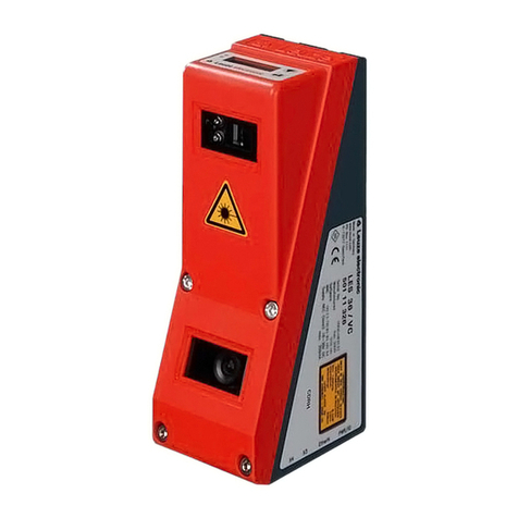
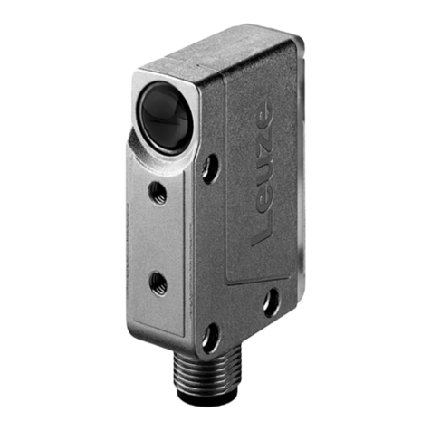
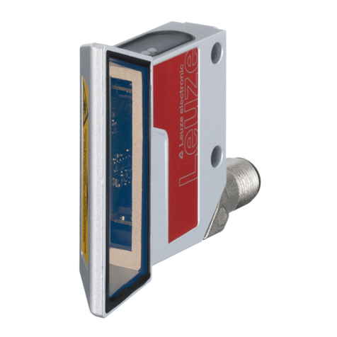
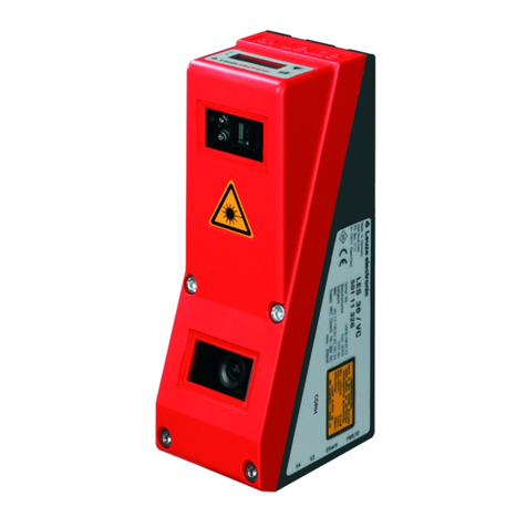
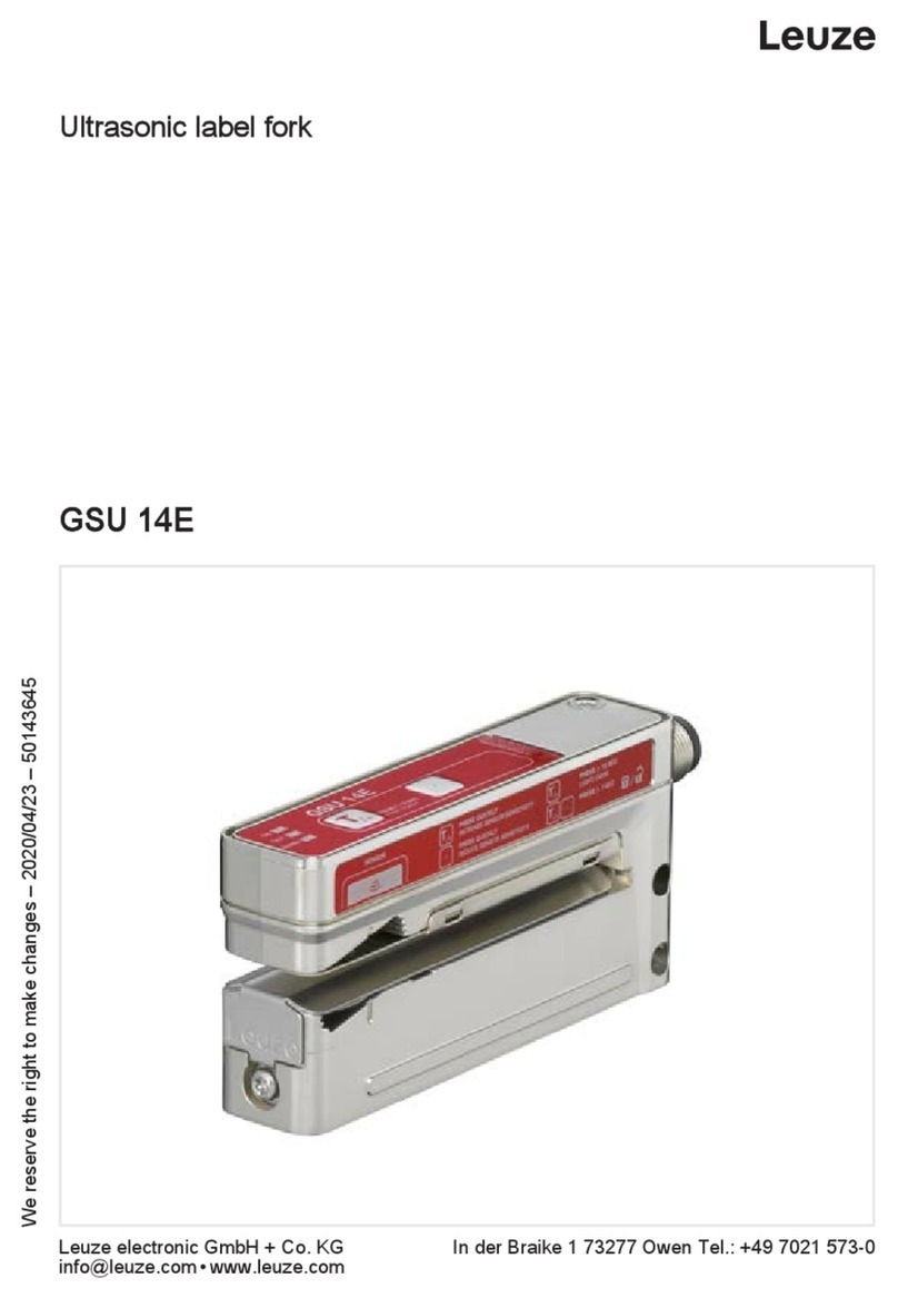
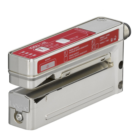
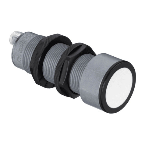
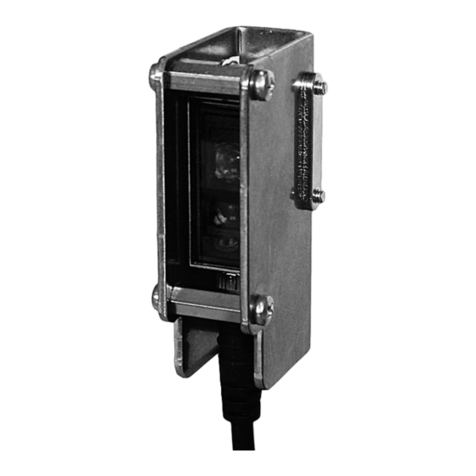
Leuze IGSU 14E User manual

IGSU14E
Ultrasonic label fork
Leuze electronic GmbH + Co. KG
In der Braike 1 73277 Owen Tel.: +49 7021 573-0
We reserve the right to make changes – 2020/05/07 – 50143646
www.leuze.com•

1Figure part
1
A
B
2

2
> 12 s
2-7 s
C
B
A
D
+> 7 s
E
F
7-12 s
2-7 s
3
3

4
2-7 s
5
7-12 s
4

6
> 12 s
7
2-7 s
5

8
+
< 2 s < 2 s
–
9
> 7 s
+
10
A
B
T
t
HIGH
LOW
≥ 20 ms ≥ 20 ms
6

11
7

Intended use
The ultrasonic label forks are ultrasonic sensors for contactless detection of the
gap between two consecutive labels on a carrier tape.
NOTICE
Observe intended use!
This product is not a safety sensor and is not intended as personnel
protection.
ÄOnly allow competent persons to put the product into operation.
ÄOnly use the product in accordance with its intended use.
Function and device operation
The label material used determines the achievable precision and the reliability of
gap detection between labels.
– Light switching: signal in the label gap.
– Dark switching: signal on the label.
1
A Label center position
B Label run
ÄTo achieve a high switching accuracy, place the label tape on the lower fork
with slight tension.
ÄAlign the label tape with the "Label center position" marking.
Overview of the operating structure via the teach and minus buttons
2
A Standard function
Normal operation after switch-on
B easyTeach (while the label tape is passing through)
(2-point calibration on carrier and label)
C Static teach (on the label carrier without transport)
(1-point calibration on carrier)
D Set switching behavior (light/dark switching)
E Deactivate/activate the
ALC
(Auto Level Control) function
(automatic optimization of the switching threshold)
F Manual locking/unlocking of the buttons on the device
8
EN

IGSU14E standard functions
During operation the sensor is always in this function.
The sensor detects label gaps with high precision and speed.
This is indicated by the yellow OUTLED and the switching output.
3
ONLED
green
Constantly ON when operating voltage is applied.
OUTLED
yellow
Indicates the switching signal.
LED is ON if the sensor detects label gaps.
The display is independent of the output setting.
WARNLED
continuous red
light
OFF: error-free operation.
ON: teaching error caused by unfavorable label material
ON:
ALC
(Auto Level Control) function is faulty.
ALCLED
yellow
ALC
(Auto Level Control) function is active.
9
EN

easyTeach while the label tape is passing through (dynamic)
During the
easyTeach
process, a two-point calibration is performed on the carrier
and the label.
NOTICE
With respect to detection reliability, the
easyTeach
process is gener-
ally to be preferred over the static teach process.
Preparation: Insert label tape into the sensor.
4
ÄPress the teach button until the green ON LED and the yellow OUT LED flash
synchronously.
ÄRelease the teach button.
ÄAllow the label tape to advance through the sensor at a maximum speed of
50m/min.
ðThe sensor indicates the belt transport by a more rapid synchronous
flashing of the green ON LED and yellow OUT LED.
– If sufficient teach values are determined, the sensor automatically terminates
the teach event and goes into standard mode.
The transport of the label tape can be stopped immediately.
– The number of labels to be transported is always based on the material com-
bination. From experience, approximately 2-10 labels should be advanced
through the sensor.
– If the teach event is faulty (e.g., unfavorable material combination, uneven
transport, jittering during transport), the red WARNLED illuminates and the
warning output (if present for the sensor model) is activated.
If the fault cannot be rectified, e.g., via the
easyTune
function, the label ma-
terial cannot be detected with the device.
Static teach on the label carrier without transport
With the static teach process, a one-point calibration is performed on the blank
carrier. This process is especially advantageous because no labels are lost while
teaching.
Preparation: depending on the label size, pull off one or more labels from the car-
rier and insert the blank area into the sensor.
5
ÄPress the teach button until the green ONLED and the yellow OUTLED flash
alternately.
ÄRelease the teach button.
10
EN
Adjusting the switching behavior of the switching output (light/dark
switching)
6
ÄPress the teach button until only the green ON LED flashes.
ÄRelease the teach button.
The green ON LED flashes for another 2 seconds and the yellow OUT LED
indicates the changed switching behavior for 2 seconds:
– Yellow OUTLED ON: switching output, light switching (signal in the label
gap)
– Yellow OUTLED OFF: switching output, dark switching (signal on the label)
ALC (Auto Level Control) function
With the
ALC
function, the sensor automatically corrects the switching threshold in
such a way that the maximum function reserve is always available during opera-
tion.
NOTICE
The
ALC
function is active by default and is indicated by illumination of
the yellow ALCLED.
In each teach event, the current signal values in the sensor are digitally deter-
mined. This results in the optimum switching threshold being calculated for maxi-
mum function reserve.
All values are saved and are non-volatile, retaining their validity as long as the dy-
namic parameters of the system remain unchanged and the material is not
changed.
Signal changes can result each time the roll is changed, even with labels that are
apparently the same.
– This is caused, for example, by material variations which affect the acoustic
impedance of the ultrasonic system (material thickness, homogeneity, etc.).
– In addition, changes to the dynamic system parameters (tape tension, mid-
dle position of the labels, jitter, etc.) could have a negative effect on the func-
tion reserve of the sensor.
With the
ALC
function, the sensor automatically corrects the switching threshold in
such a way that the maximum function reserve is always available during opera-
tion - the sensor works absolutely reliably and free of errors.
The teach event only needs to be repeated if the sensor does not switch following
a change of material.
NOTICE
When changing to another type of label, a new adjustment must gener-
ally be carried out by teaching it.
11
EN

Activate or deactivate
ALC
function
The
ALC
function can be manually deactivated and activated.
7
ÄPress the minus button (-) until the green ONLED and the yellow OUTLED
flash synchronously.
ÄRelease the minus button (-).
NOTICE
The manual deactivation/activation of the
ALC
function is stored in
non-volatile memory in the sensor.
easyTune – Manual fine tuning of the switching threshold
With homogeneous label material, the signal in the gap between twolabels is
much larger compared to the signal on the label.
For the taught switching threshold, there is a high function reserve in both the gap
as well as on the label, and the sensor functions reliably.
To achieve a better function reserve, it can be advantageous to change the taught
switching threshold, especially for inhomogeneous label material.
The sensitivity of the sensor and, thus, the switching threshold can be adjusted
with the
easyTune
function, which is in principle comparable to a potentiometer.
NOTICE
Use of the
easyTune
function temporarily deactivates the
ALC
func-
tion!
The
ALC
function is reactivated after teaching again.
8
The sensitivity of the sensor can be adjusted by pressing the teach button (+) or
the minus button (-).
Increase sensitivity:
ÄBriefly press the teach button (+).
ðA single flash of the green ON LED confirms button actuation.
Reduce sensitivity:
ÄBriefly press the minus button (-).
ðA single flash of the yellow OUT LED confirms button actuation.
12
EN

Recommended settings
Observation Measure Action
After teaching, the yellow
LED and the switching
output flicker if the label is
moved through the sen-
sor:
The function reserve on
the label is too low.
Reduce sensitivity of the
sensor
(upward shift of the
switching threshold)
Repeatedly press the mi-
nus button (-) briefly until
the sensor detects the
moving label stably and
without interruption.
In rare cases, a highly in-
homogeneous carrier
tape can affect the func-
tional reliability. The yel-
low LED and the switch-
ing output flicker if the
blank carrier tape is
moved through the sensor
without labels:
The function reserve on
the carrier is too low.
Increase sensitivity of the
sensor
(downward shift of the
switching threshold)
Repeatedly press the
teach button (+) briefly
until the sensor detects
the moving carrier tape
without labels stably and
without flickering.
Manual locking/unlocking of the buttons on the device
To protect against erroneous operation, the locking of the buttons is intended to
prevent a button on the device from accidentally being pressed. Accidental button
actuation could unintentionally trigger the
easyTune
function or the teaching of the
device and thereby deactivate the
ALC
function.
9
ÄPress the teach button (+) and the minus button (-) simultaneously until the
green ONLED flashes at approx. six times per second.
ÄRelease the teach button (+) and the minus button (-).
ðThe buttons are now locked and can no longer be operated.
ðThe buttons are unlocked using the same button combination.
NOTICE
Manual locking of the buttons on the device is stored in volatile mem-
ory.
13
EN

Sensor adjustment via teach input (pin5)
Teach-in
To teach, a teach signal is applied to the teach input (pin 5). The duration of the
teach signal (low level on the teach input) determines the teach-in function.
NOTICE
Before a low level is applied for teaching-in functions, a high level must
be applied for at least 20ms.
10
A Buttons locked
B Buttons can be operated
T Duration of the teach signal
Duration T
[ms]
Function
20…80
easyTeach
while the label tape is passing through
120…180 Static teach
220…280 Configure the switching behavior of the switching output: light
switching
320…380 Configure the switching behavior of the switching output: dark
switching
420…480 easyTune (-): reduce sensitivity
520…580 easyTune (+): increase sensitivity
620…680 Activate the
ALC
function
720…780 Deactivate the
ALC
function
14
EN

Locking the buttons via the teach input
11
Manual locking of the buttons on the device is only suitable for protecting against
tampering to a limited extent since locking can be canceled using the correspond-
ing button combination. For this reason, it is also possible to lock the buttons via
the teach input (pin 5).
– A static high signal (≥ 20ms) on the teach input locks the buttons on the de-
vice so that no manual operation is possible. The buttons can then no longer
be unlocked using the described button combination.
– If the teach input is not connected or if there is a static low signal, the but-
tons are unlocked and can be operated freely.
NOTICE
The buttons can also be locked/unlocked via IO-Link.
15
EN
This manual suits for next models
8
Table of contents
Other Leuze Accessories manuals

Leuze
Leuze ODSL 30 User manual

Leuze
Leuze BPS 8 SM 102 User manual

Leuze
Leuze GSX14E User manual

Leuze
Leuze HTU330 Series User manual

Leuze
Leuze ESB2 Series User manual

Leuze
Leuze LBK S-01 User manual

Leuze
Leuze HT25CL2 User manual

Leuze
Leuze LRS Parts list manual

Leuze
Leuze IGSU 14E SD User manual

Leuze
Leuze SET-AC User manual

Leuze
Leuze GSU12 User manual

Leuze
Leuze KRT18BW User manual

Leuze
Leuze GS63B/6.3-S8 User manual

Leuze
Leuze MLDSET-M1 User manual

Leuze
Leuze DDLS 170 Parts list manual

Leuze
Leuze KRT3CM Series User manual

Leuze
Leuze KRT18BW User manual

Leuze
Leuze DCR 200i User manual

Leuze
Leuze LES 36 Series User manual

Leuze
Leuze PRK 55 Ex Series User manual