Leuze electronic BPS 34 1
Leuze electronic Table of contents
1 General information........................................................................................................... 3
1.1 Explanation of symbols ........................................................................................................ 3
1.2 Declaration of conformity ..................................................................................................... 3
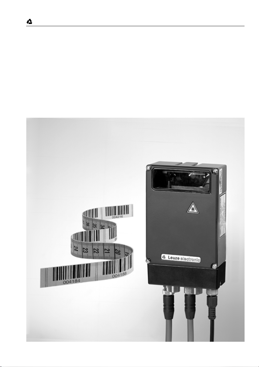
1.3 Description of the BPS 34 functions .................................................................................... 4
2 Safety notices..................................................................................................................... 5
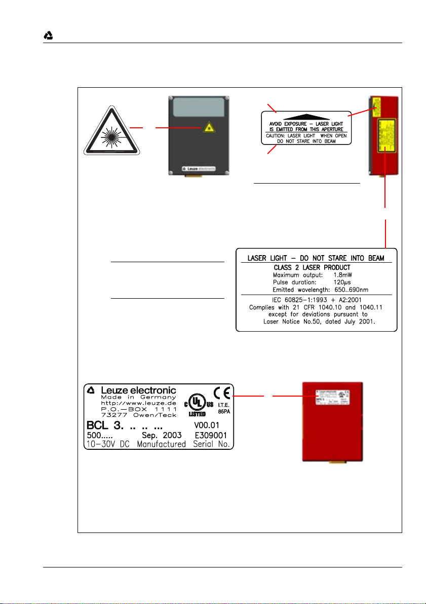
2.1 General safety notices ......................................................................................................... 5
2.2 Safety standards .................................................................................................................. 5
2.3 Intended use ........................................................................................................................ 5
2.4 Working safely ..................................................................................................................... 6
3 Commissioning steps at a glance .................................................................................... 8
4 Specifications BPS 34 ..................................................................................................... 13
4.1 General specifications BPS 34 .......................................................................................... 13
4.2 Dimensioned drawings....................................................................................................... 14
4.3 Electrical connection .......................................................................................................... 16
4.3.1 PWR IN - voltage supply and switching input/output ................................................................... 18
4.3.2 DP IN - PROFIBUS DP incoming ................................................................................................ 19
4.3.3 DP OUT - PROFIBUS DP outgoing............................................................................................. 19
4.3.4 SW IN/OUT - switching input/switching output ............................................................................ 20
4.3.5 BPS 34 reading field curve .......................................................................................................... 21
5 Connector units MS 34 … / MSD 1 101........................................................................... 22
5.1 Modular hoods with integrated connectors MS 34 103 and MS 34 105 ............................ 22
5.1.1 General information ..................................................................................................................... 22
5.1.2 Specifications of the connector units ........................................................................................... 22
5.1.3 Dimensioned drawings ................................................................................................................ 23
5.1.4 Electrical connection.................................................................................................................... 24
5.1.5 Description of the LED states ...................................................................................................... 24
5.2 Modular Service Display MSD 1 101 ................................................................................. 25
5.2.1 General information ..................................................................................................................... 25
5.2.2 Dimensioned drawing .................................................................................................................. 26
5.2.3 Electrical connection.................................................................................................................... 26
6 Barcode tape .................................................................................................................... 27
6.1 General information ........................................................................................................... 27
6.2 Specifications of the barcode tape..................................................................................... 28
6.3 Mounting the barcode tape ................................................................................................ 29
6.4 Control barcode ................................................................................................................. 32
6.4.1 Controllable functions .................................................................................................................. 33
6.5 Repair kit............................................................................................................................ 35
7 Mounting........................................................................................................................... 37
7.1 Mounting the BPS 34 ......................................................................................................... 37
7.2 Device arrangement...........................................................................................................40
7.3 Mounting the barcode tape ................................................................................................ 41