manuals.online logo
Brands
  1. Home
  2. •
  3. Brands
  4. •
  5. Leviton
  6. •
  7. Surge Protector
  8. •
  9. Leviton 47120-7 User manual

Leviton 47120-7 User manual

®
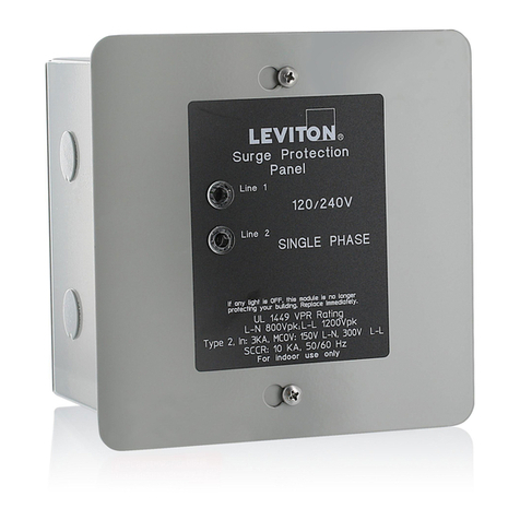
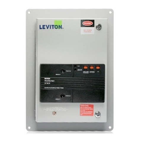
Seven Mode Panel
For branch and service entrance
Cat. Nos.:
47120-7, 47120-4X7
47277-7, 47277-4X7
Installation Instructions
PK-92954-10-00-00 REV A0
LIMITED TEN YEAR WARRANTY AND EXCLUSIONS
Leviton warrants to the original consumer purchaser and not for the benefit of
anyone else that this product at the time of its sale by Leviton is free of defects
in materials and workmanship under normal and proper use for ten years from
the purchase date.Leviton’s only obligation is to correct such defects by repair
or replacement, at its option, if within such ten year period the product is returned
prepaid, with proof of purchase date, and a description of the problem to Leviton
Manufacturing Co., Inc., Att: Quality Assurance Department, 59-25 Little
Neck Parkway, Little Neck, New York 11362-2591. This warranty excludes
and there is disclaimed liability for labor for removal of this product or
reinstallation. This warranty is void if this product is installed improperly or in
an improper environment, overloaded, misused, opened, abused, or altered in
any manner, or is not used under normal operating conditions or not in
accordance with any labels or instructions. There are no other or implied
warranties of any kind, including merchantability and fitness for a particular
purpose, but if any implied warranty is required by the applicable jurisdiction,
the duration of any such implied warranty, including merchantability and fitness
for a particular purpose, is limited to ten years. Leviton is not liable for incidental,
indirect, special, or consequential damages, including without limitation, damage
to, or loss of use of, any equipment, lost sales or profits or delay or failure to
perform this warranty obligation.The remedies provided herein are the exclusive
remedies under this warranty, whether based on contract, tort or otherwise.
For Technical Assistance Call:
1-800-824-3005 / www.leviton.com
INTRODUCTION
Transient voltage surges are short-term deviations from a
desired voltage level or signal that can occur at any time.
Such changes can result in an electronic device
malfunction, or cause extensive damage. Also termed
"spikes"
, these occurances take place as a result of
magnetic field/inductive coupling or whenever the line
current is interrupted. They can originate from either
inside a facility, or derive from outside utility lines.
Sources within a facility involve loads that are switched,
such as electric motors that are turned ON and OFF.
Outside transient influences involve utility grid switching.
DESCRIPTION
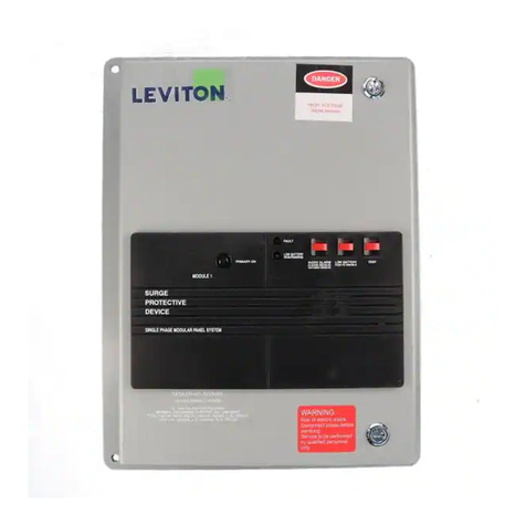
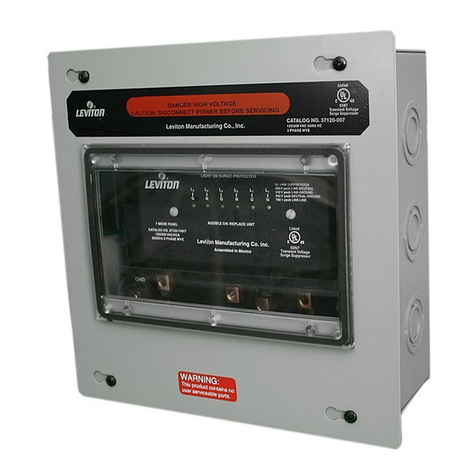
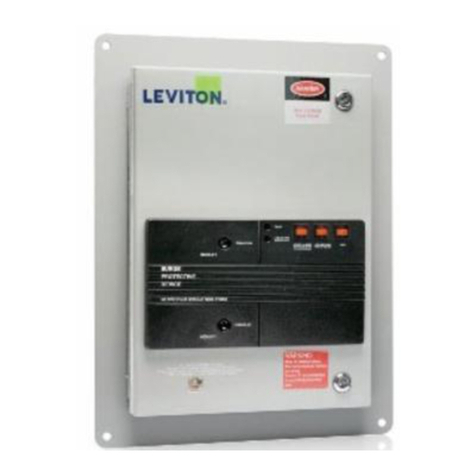
Leviton Panel Mounted devices are designed to provide
protection for microprocessor-based equipment in
industrial and commercial establishments from high
voltage transients.
SPECIFICATIONS
Ratings: 47120-7, 47120-4X7 120/208VAC, 3 Phase
47277-7, 47277-4X7 277/480VAC, 3 Phase
• Listed to UL Standard 1449 - 2nd Edition
(effective Feb. 1998).
• CSA certified.
• IEEE C62.41-1991 Category A&B Combination Wave
Suppression.
• Provides seven modes of protection: L-N (3), L-G (3),
N-G (1).
• High-energy solid-state semi-conductor surge
suppression circuitry per phase. Each Line to Neutral,
Line to Ground and Neutral to Ground.
• Each phase provided with independent thermal
fuse protection.
GENERAL INFORMATION
• Green LED diagnostic indicator for each phase.
• Acoustic as well as visual indicators.
• Interior plastic circuit enclosure for added safety and
easy servicing.
• Compatible with Decora Home Controls (DHC).
• Provided with Remote Monitoring Dry Contact
(Form C Rated 120/240V, 5A).
NOTES:
• Standard J-Box metal enclosure with pre-punched
standard size knockouts simplifies flush mounting in
typical frame construction environments, and provides
convenient connection means to existing branch panels.
• For superior local TVSS protection, use Leviton Surge
Suppression Outlets to protect against internally-
generated transients between the Seven Mode Panel
and the point of use.
• Cat. Nos. 47120-4X7 and 47277-4X7 are provided with
a NEMA 4X enclosure for outdoor installation.
• TVSS device terminal blocks accept up to #6 AWG wire.
• Recommended conductor size: 10AWG stranded.
TO INSTALL
WARNING: TO BE INSTALLED AND/OR USED IN
ACCORDANCE WITH APPROPRIATE ELECTRICAL
CODES AND REGULATIONS.
WARNING: IF YOU ARE NOT SURE ABOUT ANY PART
OF THESE INSTRUCTIONS, CONSULTA QUALIFIED
ELECTRICIAN.
WARNING: TOAVOID FIRE, SHOCK, OR DEATH; TURN
OFF POWERAT CIRCUIT BREAKER OR FUSEAND TEST
THAT THE POWER IS OFF BEFORE WIRING!
WARNING: THIS DEVICE IS NOTA LIGHTNING
ARRESTOR. IT WILL NOT SURVIVE LIGHTNING
STRIKES IN CLOSE PROXIMITY TO THE PREMISES.
WARNING: ELECTROCUTION, FATAL, OR SERIOUS
INJURYAND PROPERTY OR EQUIPMENT DAMAGE
CAN RESULT FROM FAULTY INSTALLATION AND/OR
SERVICING.ALWAYS TURN POWER OFF BEFORE
REPLACING MODULES.
WARNING: ATVSS MODULE IN A FEED-THROUGH
BRANCH CIRCUIT WILL PROVIDE PROTECTION ONLY
FOR LOADS WIRED DIRECTLY TO IT. IT WILL NOT
PROVIDE PROTECTION TO ANY OTHER MODULES ON
THE SAME BRANCH CIRCUIT.
WARNING: THIS DEVICE SHOULD BE INSTALLED ON
A LINE THAT IS SERVED BY DISCONNECT MEANS,
SUCH AS DEDICATED 20 AMP CIRCUIT BREAKERS OR
20 AMP FUSED OR 20 AMP FUSED DISCONNECT
SWITCHES.
12
PK-92954-10-00-00-A0 10/29/01, 1:24 PM1
Black
345
Fig. 2 - 47120-7, 47120-4X7 3ØInstallation
L3
L2
480V
480V
480V
277V
47277-7 / 47277-4X7
277/480VAC
3Ø
277V
277V
L1
N
WARNING: IF CONDUIT IS USED, AGREEN GROUND
WIRE MUST BE CONNECTED TO GROUND LUG.
FAILURE TO DO SO MAY RESULT IN FIRE AND/OR
SHOCK.
CAUTION: USE THIS DEVICE ONLY WITH COPPER
OR COPPER CLAD WIRE. WITH ALUMINUM WIRE USE
ONLY DEVICES MARKED CO/ALR OR CU/AL.
1. RESTORE POWER, if necessary.
2. Measure panel voltage, L-N, to determine the system
voltage. System voltage must not exceed the specified
maximum continuous RMS voltage listed on the TVSS
device label.
3. TURN OFF POWER.
4. Mount the TVSS device as close as possible to the circuit
breaker panel. Connection lead length between the TVSS
device and circuit breaker box should be minimal for best
protection. The location should also permit good visibility
of the TVSS device’s diagnostic lights.
5. Remove the circuit breaker panel cover and determine
the breaker-panel wiring entry point relative to chosen
location of the TVSS device.
NOTE: Since the circuit breaker panel and the TVSS
unit have overlapping covers, installation should allow
at least 1" of clearance from the edge of the circuit
breaker panel cover.
6. For surface-mount installations: The TVSS device
may be connected using rigid conduit to any conduit
knockout hole.
NOTE: For surface mount installation of NEMA 4X
enclosure, drill a hole in the NEMA 4X enclosure in line
with the NEMA 1 enclosure knockout to be used. Install
weather-proof conduit and seals to maintain the NEMA
4 integrity.
7. For non-surface mount installations: Secure the
TVSS to the support stud in the wall by cutting a
10" x 10" mounting hole.
8. Remove TVSS cover and connect 3/4" flexible or rigid
conduit between circuit breaker box and the TVSS using
the shortest route possible.
9. Place the TVSS device outer enclosure into the
10" x 10" mounting hole and secure it to the
exposed studs.
10. Remove clear plastic terminal cover.
11. If necessary, remove the two corner screws and the two
stand offs used for securing the Black circuit enclosure
box to the TVSS cover, allowing the Black enclosure
box to be rotated (in 90°increments) to place the
terminal lugs as close as possible to the conduit
entrance of the TVSS device.
NOTE: Do not remove center enclosure screw.
12. Replace the two screws and the two stand offs.
WIRING PROCEDURE
1. Thread wire leads through conduit to the TVSS enclosure.
2. Connect wires per appropriate wiring diagram as
follows: Black to Phase (Line 1, Line 2, Line 3). White
to Neutral. Green to Ground. For 120V, 2-Wire +
Ground operation, connect the Black wire to L1, and
Jumper terminals L2 and L3 to L1. For 240V Single
Phase (120/240V Single Phase), connect one Black wire
to terminal L1, and the other to L2. Jumper L2 to L3.
Screw terminal torque requirements: #10 - #12AWG
(35 in.-lb.), #8 AWG (40 in.-lb.), #4 - #6AWG (45 in.-lb.)
3. Replace the clear plastic terminal cover.
4. Ensure ground wire is connected to outer enclosure.
5. Replace panel cover.
6. Select circuit breakers as close as possible to each
service entrance lug. 20A circuit breakers are
recommended, and may share TVSS device and
branch circuit leads. The breakers provide additional
failure protection as well as a TVSS connection and
servicing disconnect.
NOTE: Do not connect TVSS leads directly to service
entrance lugs. This may result in fire or shock.
7. Lead lengths should be as short as possible. Connect
the Black leads to each Phase through the selected
circuit breakers. Connect the White lead to Neutral as
close as possible to Neutral entrance service lug.
NOTE: Avoid long loops and do not coil extra lead wire.
8. Replace circuit breaker panel cover.
9. Restore power at circuit breaker or fuse. Installation is
complete.
NOTE: (Remote Connection) Relay status contacts
accommodate #20 - #12AWG wire secured to terminals
using 3.5 in.-lb. of torque. If surge protection fails,
continuity will be between the “NO” and “C” contacts.
Circuit Breaker
Panel
(Cover Removed)
N
20
20
20
20
40
20
20
20
20
40
L1
L2
L3
G
47120-4X7 / 47277-4X7
47120-7
47277-7
Keep ALL connection
leads as short as
possible
Fig. 1 - Seven Mode Panel 3ØWiring
TO OPERATE
1. The Green LED on the TVSS device should be ON.
2. If during normal operation the LED turns OFF, contact a
qualified electrician to determine if Phase power is
applied. If power is present, then a transient surge has
exceeded the TVSS device rating. The unit should be
replaced and/or upgraded as soon as possible.
Fig. 3 - 47277-7, 47277-4X7 3ØInstallation
L1
L2
208V
208V
208V
120V
47120-7 / 47120-4X7
120/208VAC
3Ø
120V
120V
L3
N
PK-92954-10-00-00-A0 10/29/01, 1:24 PM2
Black

This manual suits for next models

3

Other Leviton Surge Protector manuals

Leviton 3880-DIN User manual

Leviton

Leviton 3880-DIN User manual

Leviton 51120-3R User manual

Leviton

Leviton 51120-3R User manual

Leviton 51005-WM User manual

Leviton

Leviton 51005-WM User manual

Leviton 55240-ASA User manual

Leviton

Leviton 55240-ASA User manual

Leviton 37120-7 User manual

Leviton

Leviton 37120-7 User manual

Leviton 32120-DY3 User manual

Leviton

Leviton 32120-DY3 User manual

Leviton 51240-WM User manual

Leviton

Leviton 51240-WM User manual

Leviton 57000 Series User manual

Leviton

Leviton 57000 Series User manual

Leviton 52000 Series User manual

Leviton

Leviton 52000 Series User manual

Leviton 51015-WM User manual

Leviton

Leviton 51015-WM User manual

Leviton 52412-DS3 User manual

Leviton

Leviton 52412-DS3 User manual

Leviton 37120-7 User manual

Leviton

Leviton 37120-7 User manual

Leviton 51110-PTC User manual

Leviton

Leviton 51110-PTC User manual

Leviton 51020-WMT User manual

Leviton

Leviton 51020-WMT User manual

Leviton 50240-MSA User manual

Leviton

Leviton 50240-MSA User manual

Leviton 3812 User manual

Leviton

Leviton 3812 User manual

Leviton 3862-CON User manual

Leviton

Leviton 3862-CON User manual

Leviton SmartlockPro GSIA2 User manual

Leviton

Leviton SmartlockPro GSIA2 User manual

Leviton 37120-7 User manual

Leviton

Leviton 37120-7 User manual

Leviton 57000-M3S User manual

Leviton

Leviton 57000-M3S User manual

Leviton 3803-MOD User manual

Leviton

Leviton 3803-MOD User manual

Leviton 5280 User manual

Leviton

Leviton 5280 User manual

Leviton 5480 User manual

Leviton

Leviton 5480 User manual

Leviton 51005-WM User manual

Leviton

Leviton 51005-WM User manual

Popular Surge Protector manuals by other brands

Emerson SolaHD SPD200K Series manual

Emerson

Emerson SolaHD SPD200K Series manual

M-system MMAH Series instruction manual

M-system

M-system MMAH Series instruction manual

Philips Theatre Director SPP4200WA/17 Owner's manual & warranty

Philips

Philips Theatre Director SPP4200WA/17 Owner's manual & warranty

Emerson SP-6TVN Specification sheet

Emerson

Emerson SP-6TVN Specification sheet

Vega B 61-300 FI operating instructions

Vega

Vega B 61-300 FI operating instructions

Avaya TELink 700 Flash Installation and operation manual

Avaya

Avaya TELink 700 Flash Installation and operation manual

Rocket Fish RF-HTS130 Guía De Instalación Rápida

Rocket Fish

Rocket Fish RF-HTS130 Guía De Instalación Rápida

Leutron 243 600 operating instructions

Leutron

Leutron 243 600 operating instructions

Radio Shack 61-2425 owner's manual

Radio Shack

Radio Shack 61-2425 owner's manual

SurgeAssure S50A user manual

SurgeAssure

SurgeAssure S50A user manual

Novus NVS-100E manual

Novus

Novus NVS-100E manual

CyberPower 1085 Specification sheet

CyberPower

CyberPower 1085 Specification sheet

Panamax MOD-AT2 instructions

Panamax

Panamax MOD-AT2 instructions

CyberPower CPS1090 quick guide

CyberPower

CyberPower CPS1090 quick guide

Graco 224892 Instructions and parts list

Graco

Graco 224892 Instructions and parts list

REV'IT Seesmart User information

REV'IT

REV'IT Seesmart User information

Leutron DataPro-RS485-Tr operating instructions

Leutron

Leutron DataPro-RS485-Tr operating instructions

Philips SPN5087E/10 user manual

Philips

Philips SPN5087E/10 user manual

manuals.online logo
manuals.online logoBrands
  • About & Mission
  • Contact us
  • Privacy Policy
  • Terms and Conditions

Copyright 2025 Manuals.Online. All Rights Reserved.