manuals.online logo
Brands
  1. Home
  2. •
  3. Brands
  4. •
  5. Life Fitness
  6. •
  7. Fitness Equipment
  8. •
  9. Life Fitness G5 User manual

Life Fitness G5 User manual

This manual suits for next models

1

Other Life Fitness Fitness Equipment manuals
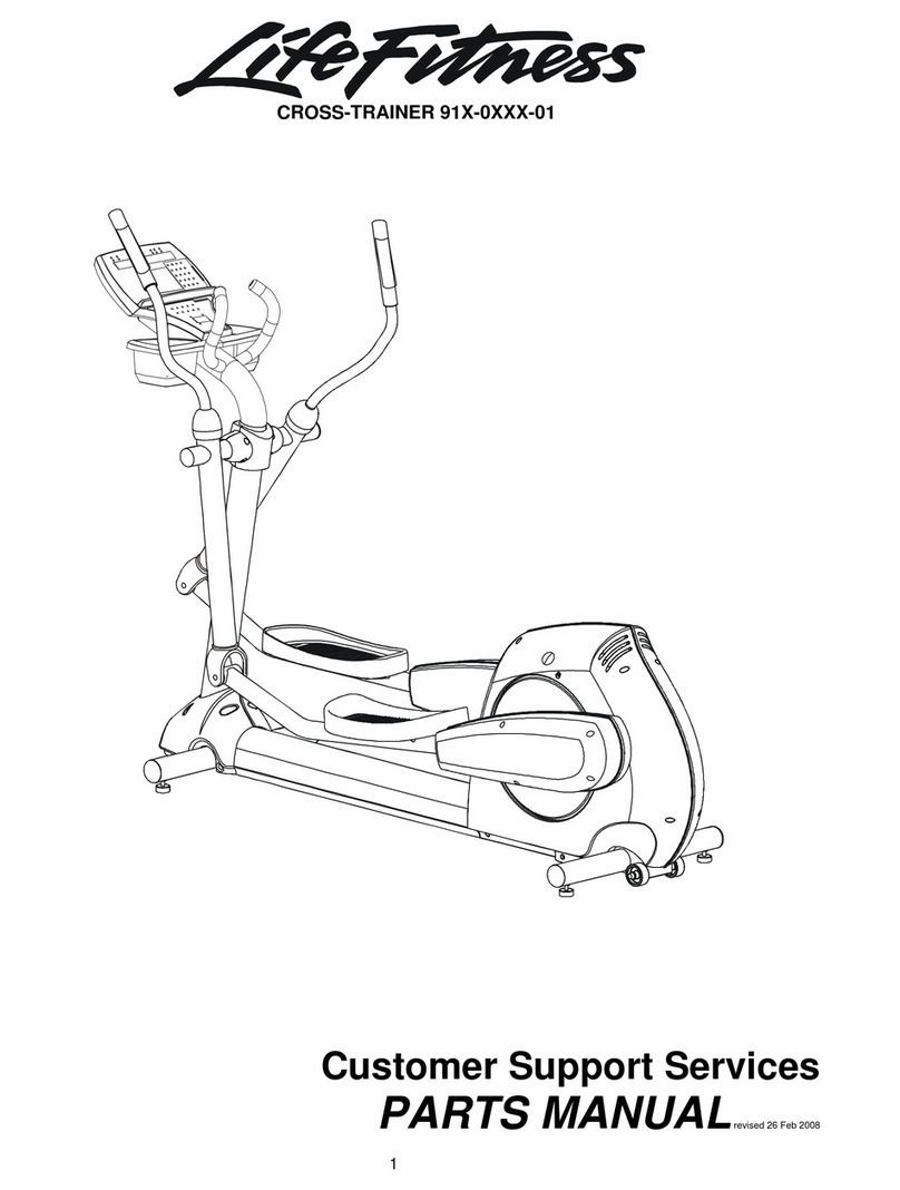
Life Fitness CLSX Installation guide

Life Fitness

Life Fitness CLSX Installation guide

Life Fitness PowerMill 95PS-03 Series User manual

Life Fitness

Life Fitness PowerMill 95PS-03 Series User manual

Life Fitness PFR-ROW-LCD User manual

Life Fitness

Life Fitness PFR-ROW-LCD User manual

Life Fitness LF-ARC-LB-B1 User manual

Life Fitness

Life Fitness LF-ARC-LB-B1 User manual

Life Fitness Leg Extension User manual

Life Fitness

Life Fitness Leg Extension User manual

Life Fitness Base X1 User manual

Life Fitness

Life Fitness Base X1 User manual

Life Fitness 935i User manual

Life Fitness

Life Fitness 935i User manual

Life Fitness Strength 8501 VKR OPTION User manual

Life Fitness

Life Fitness Strength 8501 VKR OPTION User manual

Life Fitness Integrity SL User manual

Life Fitness

Life Fitness Integrity SL User manual

Life Fitness INTEGRITY SERIES M051-00K61-A137 User manual

Life Fitness

Life Fitness INTEGRITY SERIES M051-00K61-A137 User manual

Life Fitness Club Series User manual

Life Fitness

Life Fitness Club Series User manual

Life Fitness INSIGNIA SERIES User manual

Life Fitness

Life Fitness INSIGNIA SERIES User manual

Life Fitness FS4 User manual

Life Fitness

Life Fitness FS4 User manual

Life Fitness CLUB Series ARM CURL User manual

Life Fitness

Life Fitness CLUB Series ARM CURL User manual

Life Fitness X8 User manual

Life Fitness

Life Fitness X8 User manual

Life Fitness X3 Cross-Trainers Supplement

Life Fitness

Life Fitness X3 Cross-Trainers Supplement

Life Fitness SC9500 User manual

Life Fitness

Life Fitness SC9500 User manual

Life Fitness GK61-00002-0008 Original operating manual

Life Fitness

Life Fitness GK61-00002-0008 Original operating manual

Life Fitness Arctic Silver 95S User manual

Life Fitness

Life Fitness Arctic Silver 95S User manual

Life Fitness 95X-0XXX-05 User manual

Life Fitness

Life Fitness 95X-0XXX-05 User manual

Life Fitness X3 Cross-Trainers User manual

Life Fitness

Life Fitness X3 Cross-Trainers User manual

Life Fitness M051-00K61-A039 User manual

Life Fitness

Life Fitness M051-00K61-A039 User manual

Life Fitness G2 User manual

Life Fitness

Life Fitness G2 User manual

Life Fitness CLUB SERIES FLY User manual

Life Fitness

Life Fitness CLUB SERIES FLY User manual

Popular Fitness Equipment manuals by other brands

Revitive Arthritis-Knee user manual

Revitive

Revitive Arthritis-Knee user manual

Domyos BM100 operating instructions

Domyos

Domyos BM100 operating instructions

Movement EDGE PUXADA ALTA Assembly manual

Movement

Movement EDGE PUXADA ALTA Assembly manual

Lifeline LLUWB-BLK owner's manual

Lifeline

Lifeline LLUWB-BLK owner's manual

Precor CW-816 Assembly guide

Precor

Precor CW-816 Assembly guide

Balanced Body Precision Rotator Discs manual

Balanced Body

Balanced Body Precision Rotator Discs manual

G-FITNESS AIR ROWER user manual

G-FITNESS

G-FITNESS AIR ROWER user manual

CAPITAL SPORTS Dominate Edition 10028796 manual

CAPITAL SPORTS

CAPITAL SPORTS Dominate Edition 10028796 manual

Martin System TT4FK user guide

Martin System

Martin System TT4FK user guide

CIRCLE FITNESS E7 owner's manual

CIRCLE FITNESS

CIRCLE FITNESS E7 owner's manual

G-FITNESS TZ-6017 user manual

G-FITNESS

G-FITNESS TZ-6017 user manual

Accelerated Care Plus OMNISTIM FX2 CYCLE/WALK user manual

Accelerated Care Plus

Accelerated Care Plus OMNISTIM FX2 CYCLE/WALK user manual

pedalo 20230165 manual

pedalo

pedalo 20230165 manual

Saebo SaeboStim Pro Instructions for use

Saebo

Saebo SaeboStim Pro Instructions for use

Performance HyperVibe User instructions

Performance

Performance HyperVibe User instructions

Scalamobil S27 Operator's manual

Scalamobil

Scalamobil S27 Operator's manual

Precor Experience Series Service manual

Precor

Precor Experience Series Service manual

FYTTER RedMIUM BENCH BE-T6R manual

FYTTER

FYTTER RedMIUM BENCH BE-T6R manual

manuals.online logo
manuals.online logoBrands
  • About & Mission
  • Contact us
  • Privacy Policy
  • Terms and Conditions

Copyright 2025 Manuals.Online. All Rights Reserved.

CLASSH
PART#LEA7767401REV.A
VERSION:LFG5-101
DATE: 07-01-04
WARNING:
Read and follow all directions
for each step to insure proper
assembly of this product.
G5 CABLE
MOTIONTECHNOLOGY
GYM SYSTEM
USERGUIDE
THERE IS A RISK ASSUMED BY INDIVIDUALS WHO USE THIS TYPE OF
EQUIPMENT. TO MINIMIZE RISK FOLLOW THESE RULES!
1. Before using, read all the warnings and instructions
on the use of this machine. Use only for intended
exercise. DO NOT modify the machine.
2. Obtain a medical exam before beginning any
exercise program.
3. Keep body and clothing free of all moving objects.
4. Inspect the machine before use. DO NOT use it if it
appears damaged. DO NOT attempt to fix a broken or
j
ammed machine. Notify your authorized Life Fitness
dealer before use and have repairs made by an
authorized service technician.
5. Be certain that weight pin is completely inserted.
Use only the pin provided by the manufacturer. If
unsure, call your authorized Life Fitness dealer.
6. Never pin the weights or prop plate into an elevated
position. DO NOT use the machine if found in this
condition. DO NOT attempt to fix. Notify your
authorized Life Fitness dealer.
7. Inspect cables and their connections before using
machine. Pay particular attention to the cable ends.
DO NOT attempt to fix. Notify your authorized
Life Fitness dealer before use and have repairs made
by an authorized service technician.
8. Make sure all spring loaded pull pins are fully
engaged in the adjustment position and fully tighten
thumbscrew before use.
9. Children must not be allowed near this machine.
Supervise teenagers.
IMPORTANT SAFETY INFORMATION
TABLE OF CONTENTS
Safety Statement.............2
General Notes.................2
Gym Layout...................3
Parts List........................4
Exploded View...............5
NOTE: In a continual effort to improve our products, specifications are subject to change
2004 Life Fitness, a division of Brunswick Corporation. All rights reserved.
Life Fitness is a trademark of Brunswick Corporation
www.LifeFitness.com
2
Tool Requirements
and Hardware.................6
Assembly Instructions.....7-17
General Maintenance.......18
Warranty Statement.........19
Product Services.............20
Insert-Registration Card
©
Please note:
* Thank you for purchasing the LFG5 Cable Motion Tcchnology Gym System. Please read
these instructions thoroughly and keep them for future reference. This product must be
assembled on a flat, level surface to assure its proper function.
* This product must be assembled on a flat, level surface to assure its proper function.
DO NOT securely tighten any frame connections until the entire frame has been assembled,
unless otherwise stated.
GYM DIMENSIONS
3
4
COMPONENTS LIST
ITEM NO. QTY. PART NO. DESCRIPTION
11LEA7728201 PTDASSY,FRONTUPRIGHT
21LEA7701601 PTDASSY,FOOTPLATE
31LEA7729801 PTDASSY,ROLLERPADADJ.
41LEA7701701 PTDASSY,LEFTUPRIGHT
51LEA7701801 PTDASSY,RIGHTUPRIGHT
61LEA7611701 WLDMT,GUIDEROD
71LEA7746101 PTDASSY,TOPPULLEYS
81LEA7761701 PTDASSY,FRONTSHROUD
91LEA7761601 PTDASSY,G5, TOPSHROUD
10 1LEA776240 PTDASSY,HEADPLATEPULLEY
112LEA7754501 PTDASSY,FLOATINGPULLEYS
12 1LEA6925501PTDASSY,HEADPLATE20"
13 2LEA7682001PLATE,REARBOTTOM
14 1LEA7622001ASSY,SELECTORPIN
15 1LEA7755301COVERTOP
16 1LEA7755401COVERTOPBACK
17 1LEA7755501COVERTOPFRONT
18 1LEA7755601COVERMIDBACK
19 1LEA7755701COVERMIDFRONT
20 1AK58-00245-0000 MEDALLION;"BUG";PUR
21 2LEA3245501COLLAR,1" IDSHAFTALUM
222LEA6920201 GUIDEROD,1" O.D.10GAX73
23 2LEA6020602BEARING,FLG1/2IDX5/8 ODX1/2
242LEA7749701CUSHION, WEIGHT STACK
2514LEA3223401 SCREW, 10-32 X6PHL PANTTSTBZ
2610LEA3226003 SCREW, 6-20 X 8 PHLPANPLT BZ
274LEA3249205.375HXS SOCCS SS X 1.00
28 28 LEA3236601WASHER,3/8 SAESS
29 1LEA3245307NUT,HEXSS
30 4LEA3245401BSHNG,GUIDEROD1 IDX1-1/2
316LEA3249203.375HXS SOCCS SS X .750
32 1LEA7705402SHAFT,.50 DIASLOTTEDX1.67
33 7LEA3249101NUT,.375 -16NYLOCKSS
349LEA3249214.375HXS SOCCS SS X 3.50
352LEA3249211.375HXS SOCCS SS X 2.50
36 2LEA7749801BUMPER,HEADPLATE
37 6LEA7726601CABLECONNECTENDS
38 2LEA7745601SHORTHANDLE
39 2LEA7745701LONGHANDLE
40 2LEA7745501ADJUSTABLEHANDLE
41 1LEA7745801FOOTSTRAP
42 2LEA7746001GUIDECABLE
431LEA7745401UPPER CABLE(SHORT)
44 2LEA7745402LOWERCABLE(LONG)
45 1LEA7767401USERGUIDE
**SEESHEET13,FIGURE 7 FORADDITIONALPARTNUMBERS
**
5
EXPLODEDVIEW
6
0123456
1/2 1/2 1/2 1/2 1/2 1/2
BOLT LENGTH
REQUIRED TOOLS:
HARDWARE:
* 9/16” wrench
* Ratchet and 9/16” socket
* Adjustable wrench
* Tape measure
* Two 8mm Allen wrenches
7
0123456
1/2 1/2 1/2 1/2 1/2 1/2
FIGURE 1
STEP 1:
LOOSELY assemble bottom LEFT UPRIGHT (4) and RIGHT UPRIGHT (5) to FRONT UPRIGHT (1) using four 3/8 x 3-1/2
BOLTS (34), eight 3/8 WASHERS (28) and four 3/8 NUTS (33) and TOP PULLEYS (7)
LOOSELY assemble upper LEFT FRAME (4) and RIGHT FRAME (5) to FRONT UPRIGHT (1) and TOP PULLEYS (11),
using four 3/8 x 3/4 BOLTS (31), four 3/8 WASHERS (28) as illustrated in FIGURE 1
NOTE:
THE TOP PULLEY WELDMENT ATTACHES TO THE INSIDE OF THE UPRIGHT SIDES AND THE ORIENTATION
S
SHOULD BE SO THE ARROW POINTS FORWARD AS SHOWN
FIGURE 2
8
STEP 2:
LOOSELY attach FOOT PLATE (2) to front of FRONT UPRIGHT (1) using two 3/8 x 3/4 BOLTS (31),
and two 3/8 WASHERS (28).
LOOSELY attach the FOOT PLATE (2) to the sides of UPRIGHTS (4) and (5) using two 3/8 x 3-1/2 BOLTS (34)
and two 3/8 WASHERS (28)
STEP 3:
Insert two BUSHINGS (30) into bottom of FRONT UPRIGHT (1), slide one CUSHION (24) to bottom of each GUIDE ROD (22)
and insert both GUIDE RODS (22) thru BUSHING GUIDES (30) and holes located at bottom of FRONT UPRIGHT (1)
CAREFULLY slide HEAD PLATE (12) over top of GUIDE RODS (22) followed by two BUMPER (36),
two COLLARS (21), two BUSHINGS (30) and position BRACKET (6) over top of GUIDE RODS (22)
CAREFULLY slide guide rod assembly under top FRONT UPRIGHT (1) and place TOP SHROUD (9) over top of
FRONT UPRIGHT (1) and assemble together using three 3/8 x 3-1/2 BOLTS (34), six 3/8 WASHERS (28)
and three 3/8 NUTS (33).
Slide ring of SELECTOR PIN (14) over stem of HEAD PLATE (12) screw HEX NUT (29) onto HEAD PULLEY (10)
then screw HEAD PULLEY (10) into stem of HEAD PLATE (12).
SECURLY TIGHTEN ALL FRAME CONNECTIONS
NOTE:
THREADED SHAFT OF HEAD PULLEY (10) SHOULD BE SCREWED INTO THE STEM APPROXIMATLY 1”
AND HEX NUT SHOULD BE TIGHTENED SECURELY
FIGURE 3
9
TIGHTEN SECURLEY
STEP 4
Taking one end of UPPER (SHORT) CABLE (43) insert thru top front pulley and follow routing illustration to
HEAD PLATE PULLEY (10) and continue to other side ending at the other top front pulley.
CABLE MUST BE INSERTED BETWEEN PULLEY AND PULLEY GUIDES AND MOVE FREELY
10
FIGURE 4