IDEAL 61-605 User manual

#61-605
Digital Multimeter
Instruction Manual
WARNING
Read First: Safety Information
Understand and follow operating instructions carefully.
Use the meter only as specified in this manual; other-
wise, the protection provided by the meter may be
impaired.
WARNING
To avoid possible electric shock, personal injury or death follow these guidelines:
• Do not use if meter appears damaged. Visually inspect the meter to ensure
case is not cracked and back case is securely in place.
• Inspect and replace leads if insulation is damaged, metal is exposed, or
probes are cracked. Pay particular attention to the insulation surrounding the
connectors.
• Do not use meter if it operates abnormally as protection maybe impaired.
• Do not use during electrical storms or in wet weather.
• Do not use around explosive gas, dust, or vapor.
• Do not apply more than the rated voltage to the meter.
• Do not use without the battery and the back case properly installed.
• Remove the test leads from the circuit prior to removing battery cap.
• Do not attempt to repair this unit as it has no user-serviceable parts.
CAUTION
To protect yourself, think "Safety First":
• Voltages exceeding 30VAC or 60VDC pose a shock hazard so use caution.
• Use appropriate personal protective equipment such as safety glasses, face
shields, insulating gloves, insulating boots, and/or insulating mats.
• Before each use:
- Perform a continuity test by touching the test leads together to verify the
functionality of the battery and test leads.
- Use the 3 Point Safety Method. (1) Verify meter operation by measuring a
known voltage. (2) Apply meter to circuit under test. (3) Return to the
known live voltage again to ensure proper operation.
• Never ground yourself when taking electrical measurements.
• Connect the black common lead to ground before applying the red test lead to
voltage. Disconnect the red test lead from the voltage first.
• Always work with a partner.
• When using the probes, keep fingers as far behind the probe tips as possible.
Features:
• Auto/manual ranging meter
• Measures AC/DC Voltage and Resistance
• Audible continuity
• Diode Test
• Data hold
• Auto Power Off
• Low Battery Indicator
• Compact case with built-in test leads
• Electronic overload protection on all ranges
MK
RANGE HOLD
AC/DC
Open case to access
test leads.
2
ND 4950-3 61-605 Instructions 10/27/06 9:32 AM Page 1
99 Washington Street
Melrose, MA 02176
Fax 781-665-0780
TestEquipmentDepot.com

OPERATION:
Auto Ranging Mode
The meter defaults to autoranging mode when powered on. In this mode, the
meter automatically selects the best range to display the measurement.
Manual Ranging Mode
By pressing the Range button on the meter, the manual range mode will override
the autoranging feature of the meter. “RANGE” appears in the the display.
Continue pressing the Range button until the desired range is obtained. The
ranges will cycle from lowest to highest. Use this mode to lock in a specific
range for repeated measurements.
To return to the autoranging mode, either depress the Range button for greater
than 2 seconds or turn the meter off and then back on again.
Data Hold Feature
Press the Hold button on the meter to toggle in and out of the data hold mode.
“HOLD” appears in the display when data hold is active. Use the data hold fea-
ture to lock a measurement reading on the display. Press the Hold button again
to unlock the display and obtain a real-time reading.
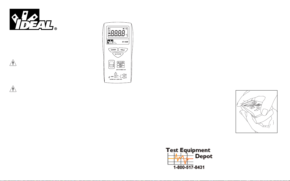
Mode Switch (AC/DC) & (Ω/ / ) Feature
Press this button to switch between AC and DC in the voltage measurement
mode of the function switch. Press this button to toggle between ohms, continu-
ity, and diode functions when in the Ω// position of the function switch.
The meter display will indicate which function is selected.
Auto Power Off (APO) Feature
The meter automatically powers itself down after about 10 minutes of no use.
Press any button, and the meter will wake up and display the last reading taken
before power down. This feature can be overridden by holding the Range button
while sliding the function switch from Off to any other position. Turning the
meter off will restore the APO default.
Measuring Voltage:
• Slide the function switch to the Volt position.
Note: The measurement mode defaults to AC voltage.
• If measuring DC voltage, use the AC/DC button to toggle to DC voltage. The meter
display will confirm the active mode (AC or DC) on the left side of the display.
• Hold the test leads behind the finger guards and apply the lead tips in parallel
to the circuit under test.
• The meter will sense the level of voltage, automatically range to obtain the best
resolution, and accurately display the measurement.
Note: To measure millivolts, use “RANGE” button to manually select mV range.
CAUTION: For maximum safety, do not hold the meter in your hands
while measuring higher voltages.
If the meter displays zero or low volts, ensure that the meter is prop-
erly set to measure AC or DC volts and verify on a known live source.
Measuring Resistance (Ohms):
• Verify the circuit is de-energized to obtain accurate measurements.
• Slide the function switch to the Ω/ / position.
Note: The measurement mode defaults to Ohms (Ω).
• Hold the test leads behind the finger guards and apply the lead tips to the
component or circuit under test.
• The meter will sense the level of resistance, automatically range to obtain the best
resolution, and accurately display the measurement.
Verifying Continuity ( / ):
• Verify the circuit is de-energized.
• Slide the function switch to the Ω/ / position.
Note: The measurement mode defaults to Ohms (Ω).
• Press the Ω// button once to toggle to Continuity. The meter display
should show the / in the upper right corner.
• Hold the test leads behind the finger guards and apply the lead tips to the
component or circuit under test.
• The meter will sense the level of resistance and beep if the resistance is less
than 25 Ωto confirm that continuity is present.
3 4
ND 4950-3 61-605 Instructions 10/27/06 9:32 AM Page 3

Testing Diodes ( / ):
• Slide the function switch to the Ω/ / position.
Note: The measurement mode defaults to Ohms (Ω).
• Press the Ω// button twice to toggle to the Diode test mode. The meter
display should show the / in the upper right corner.
• Ensure the circuit is de-energized to prevent inaccurate readings.
• Apply the red test lead to the anode of the diode and the black lead to the
cathode (gray ring). Verify the forward voltage drop is about 0.6V for silicone.
• Reverse the test lead connections. Verify an "OL" reading in the display.
• If the diode is shorted, 0mV will be displayed.
• If the diode is opened, "OL" will be displayed both directions.
Note: Audible indication occurs at <0.25V.
Battery Replacement:
• Ensure test leads are disconnected from any
circuit or components.
• Remove the screw from the battery cover.
• Remove the battery cover.
• Replace batteries with two 1.5V button cell
batteries.
• Assemble the back case on the meter and re-tighten the screw.
Maintenance:
• Clean the case with a damp cloth and mild detergent. Do not use abrasives or
solvents.
Service, and Replacement Parts:
No user-serviceable parts.
For replacement parts or to inquire about service information contact
IDEAL INDUSTRIES, INC. at 1-877-201-9005 or visit our website
www.testersandmeters.com.
Specifications:
Display: 3-1/2 digit LCD with 2000 counts
Polarity: Automatic, positive implied, (-) polarity indication.
Overrange: "OL" indication in display.
Measurement Rate: 2 times per second, nominal.
Auto Power Off: Approximately after 10 minutes of non-use
Battery Life: 70 hours continuous with alkaline
Low Battery Indication: The " " is displayed when battery voltage drops
below operating level.
Altitude: 6561.7 ft. (2000m)
Accuracy: Stated accuracy at 23°C ±5°C, < 75% R.H.
Power Supply: (2) 1.5V button cell batteries (NEDA 1166A, IEC LR-44).
Operating Environment: 32°F to 122°F (0°C to 50°C) at < 70% R.H.
Storage Environment: -4°F to 140°F (-20°C to 60°C) at < 80% R.H.
Dimensions: 4.9"H x2.4"W x0.9"D
(125mm H x60mm W x24mm D)
Weight: 3.9 oz (110g)
Accessories included: Built-in Test Leads, (2) 1.5V button cell batteries,
operating instructions.
Safety: Complies with UL 61010B-1, UL61010B-2-031,
EN 61010-1, EN61010-2-031, Cat II-600V,Cat III-300V
CUS N12966
5 6
ND 4950-3 61-605 Instructions 10/27/06 9:32 AM Page 5

Ranges & Accuracies:
Input Impedance is 9.1MΩ(20-600V AC/DC), 10MΩ(2V AC/DC), 100MΩ
(0-200mV AC/DC)
Double Insulation
Instrument has been evaluated and complies with insulation category II (overvolt-
age category II). Pollution degree 2 in accordance with IEC-644. Indoor use.
Warranty Statement:
This tester is warranted to the original purchaser against defects in material and
workmanship for the lifetime of the product. During this warranty period, IDEAL
INDUSTRIES, INC. will, at its option, replace or repair the defective unit, subject
to verification of the defect or malfunction. This warranty does not apply to
defects resulting from abuse, neglect, accident, unauthorized repair, alteration, or
unreasonable use of the instrument.
Any implied warranties arising out of the sale of an IDEAL product, including but
not limited to implied warranties of merchantability and fitness for a particular
purpose, are limited to the above. The manufacturer shall not be liable for loss of
use of the instrument or other incidental or consequential damages, expenses, or
economic loss, or for any claim or claims for such damage, expenses or
economic loss.
State laws vary, so the above limitations or exclusions may not apply to you.
This warranty gives you specific legal rights, and you may also have other rights
which vary from state to state.
Function Range and Accuracy Overload
Resolution Protection
AC Voltage 200.0mV/2.000V/20.00V/200.0V/600V 4.0% + 5 digits 600 VDC or AC rms
(50/60 Hz)
DC Voltage 200.0mV/2.000V/20.00V/200.0V/600V 2.0% + 2 digits 600 VDC or AC rms
200.0Ω2.0% + 5 digits
Resistance
2.000kΩ/20.00kΩ/200.0kΩ2.0% + 4 digits
450 VDC or AC rms
2.000MΩ3.0% + 4 digits
20.00MΩ5.0% + 5 digits
Continuity Audible indication < 25ΩN/A 450 VDC or AC rms
Response time: 500ms
Diode Test current: 1.2mA 3.0% + 3 digits
Open circuit volt: 3.0 VDC typical
~
7
ND 4950-3 61-605 Instructions 10/27/06 9:32 AM Page 7
Test Equipment Depot - 800.517.8431 - 99 Washington Street Melrose, MA 02176
FAX 781.665.0780 - TestEquipmentDepot.com
Table of contents
Other IDEAL Multimeter manuals

IDEAL
IDEAL 61-494 User manual

IDEAL
IDEAL 61-764 User manual

IDEAL
IDEAL 61-312 User manual

IDEAL
IDEAL ND 2365-1 User manual

IDEAL
IDEAL ND 2366-1 User manual

IDEAL
IDEAL 61-340 User manual

IDEAL
IDEAL Resi-Pro 310 Series User manual

IDEAL
IDEAL ND 2352-1 User manual

IDEAL
IDEAL ND 2351-1 User manual

IDEAL
IDEAL ND 2350-1 User manual

IDEAL
IDEAL 61-340 User manual

IDEAL
IDEAL 61-497 User manual

IDEAL
IDEAL 61-497 User manual

IDEAL
IDEAL 602 User manual

IDEAL
IDEAL 61-354 (TRMS) User manual

IDEAL
IDEAL 480 Series User manual

IDEAL
IDEAL 61-797 User manual

IDEAL
IDEAL 61-681 User manual

IDEAL
IDEAL ND 2385-1 User manual

IDEAL
IDEAL 61-704 User manual