LSL 120H125 Install guide

—
R
e
W
M
—
————
—
e
v. 00 31/01/20
1
W
ichtige H
Lese
n
diese
Mont
a
nega
t
Im F
o
Hinw
e
M
ontage:
Zur
S
abge
k
Brem
tropf
e
auto
r
Griffa
Origi
n
V
or
d
—
———
—
1
1
inweise:
n
Sie die A
n
Montage
n
a
ge in eine
r
t
iv beeinflu
s
o
lgenden w
e
e
ise.
Warnun
g
Leben g
e
Tipp zur
S
icherheit d
k
lemmt we
r
shydraulikl
e
e
n! Monta
g
r
isierten F
a
rmaturen,
n
allenker e
n
d
er Demon
t
—
————
—
A
rtik
e
Pr
o
M
o
n
leitung so
r
n
ur durch,
w
r
Fachwerk
s
s
sen und Ih
er
den die u
g
! Wichtig
e
e
fährdet s
e
Montage,
P
er elektris
c
r
den. Die T
a
e
itung dem
g
e der Bre
a
chwerkst
a
Bedienun
g
n
tfernen.
t
age der o
r
—
———
—
e
l-Nr. : 1
o
dukt :
S
o
dell :
H
Typ :
S
r
gfältig durc
w
enn Sie d
a
s
tatt. Ein fe
re Gesund
h
nten aufge
f
e
r Montag
e
e
in.
P
flege ode
Le
n
c
hen Syste
m
a
nkabdeck
u
ontieren.
V
msleitung
a
tt durchg
e
g
sarmatur
e
r
iginalen
G
—
Zube
h
20H125
S
uperbike
H
onda CB
R
S
C59
h und bea
c
a
für qualifizi
e
hlerhafter
A
h
eit und Ihr
f
ührten Sy
m
e
-Hinweis.
r zur Verm
n
kerkit mo
m
e sollte
w
u
ng muss d
V
orsicht:
B
und das
e
führt wer
d
e
n und
H
G
abelbrück
h
ör von
A
n
b
Lenkerki
t
R
1000R
R
c
hten Sie al
l
e
rt sind, an
A
nbau kann
Leben gef
ä
m
bole verw
a
Bei Nicht
b
eidung vo
n
ntiert
w
ährend de
emontiert
w
B
remsflüssi
g
Entlüften
d
d
en.
H
ydraulikzy
l
e unbedin
g
—
b
auan
t
R
2008
l
e Sicherhe
dernfalls e
m
das Fahrv
e
ä
hrden.
a
ndt, beach
b
eachtung
n
Schäden
r Montage
w
erden.
g
keit darf
n
d
er Brem
s
l
inder vo
m
g
t Vorderr
a
Das O
r
leitu
n
itshinweise
m
pfehlen w
e
rhalten de
ten Sie bitt
e
können G
e
.
die Batteri
e
n
icht auf V
e
s
anlage s
o
m
Lenker
a
d entlast
e
r
iginal
—
Seite 1
n
g
. Führen Si
ir dringend
s Motorrad
e
e
diese
e
sundheit
u
e
am Minu
e
rkleidungs
o
llte von e
demonti
e
e
n!
A
uch i
s
—
—
von 3
e
die
e
s
u
nd
spol
teile
iner
e
ren.
s
t es

—
R
e
—
————
—
e
v. 00 31/01/20
1
ratsa
könn
Buch
s
A
bde
c
der
M
ca. 1
werd
e
V
org
e
Neue
anzie
Lenk
a
erfor
d
zu e
r
beilie
g
werd
e
Kleb
s
origin
V
erkl
Spie
g
Ø6x
Ø
Spie
g
tausc
Gum
m
Schr
a
Nun
Lenk
e
Tank
v
ausr
e
Bedi
e
müs
s
oder
Arm
a
dass
Gasg
unte
n
Scha
Kup
p
Kont
r
sich
lässt
ande
r
Brem
s
her ki
Halte
gege
n
origin
mit d
e
Sche
i
Prüfe
Baut
e
und
k
von
L
zur
F
linke
G
verkl
e
—
———
—
1
1
m, einen
B
en. Gabel
b
s
en (l=17
m
c
kung des
Z
M
ontage de
r
5Nm ange
z
e
n. Danach
e
schriebe
n
n Lenker,
hen und n
a
a
nschlag
d
erliche Fr
e
r
reichen,
m
g
ender Dis
t
e
n. Diese
S
s
toff aus
alen Lenk
a
eidung
g
elverschra
u
Ø
25x6 un
t
g
elschraub
e
hen. Die
V
m
ischeibe
Ø
a
ube M5x2
5
die Griffar
m
e
r befesti
g
v
erkleidung
e
ichend
e
nelement
e
s
en Lenke
r
135-001
A
a
turen weit
e
die Griff
e
riff so m
o
n
zei
g
lterelemen
p
lungsarm
a
r
ollieren S
der Brem
s
und kei
n
r
en Baute
i
s
sattel lös
e
ppen um di
r des Bre
m
n
den beili
e
alen Schra
u
e
r Buchse
Ø
i
be M6 am
n Sie vor
e
ile den Fr
e
k
orrigieren
S
L
enker und
F
ixierung n
ö
G
riffgummi
e
ben.
—
————
—
B
lick auf
b
rücke geg
e
m
m) und
Z
ündschlo
s
r
Gabelbrü
c
z
ogen und
die Steuer
n
er Lenker
t
Typ N1
a
ch Abschl
u
begren
z
e
igängigkei
t
m
uss der L
t
anzscheib
e
S
cheiben
s
dem Fa
c
a
nschlag zu
anheben
:
u
bung mit
t
erlegen
e
gegen di
e
V
erkleidung
Ø
8xØ30x7
5
verwende
m
aturen p
r
g
en und
a
wieder
Freiga
n
e
und H
e
r
endstück
e
A
..) ver
w
e
r außen
m
e
über die
o
ntieren, d
a
g
en.
Z
ten und
a
tur ca. 25
m
ie bei dru
c
s
hebel bi
s
n
esfalls
v
i
len hat! (
e
n und auf
d
e Kolben z
u
m
sflüssigk
e
e
genden ta
u
u
ben befes
Ø
11,7x2,75
x
Halter vers
c
der endf
e
e
igang zu T
a
S
ie bei Be
d
Bedienele
m
ö
tigen Boh
r
mit einem
g
—
———
—
Seite 3 z
u
e
n Superbi
k
neuen Sc
h
s
ses und d
e
c
ke ist dara
u
dann die
kopfmutter
t
yp: LSL-S
in den Kl
e
u
ss der ges
a
z
en! U
m
t
für die V
e
enkanschl
a
e
n (t=2mm)
s
ind mit g
e
c
hhandel
kleben.
:
Die
der Gum
m
und die
e
beiliegen
d
am Halte
unterlege
n
n.
r
ovisorisch
a
usrichten
montier
e
n
g für
e
bel zu
e
e
(Art.-Nr.:
w
endet u
m
ontiert w
e
Endstüc
k
a
ss die Z
ü
Z
wischen
der Bre
m
m
m Platz l
a
c
kloser Br
e
s
zum Gri
f
v
orher Ko
n
Dazu einf
a
d
er Scheib
e
u
rück zu dr
e
itsreserv
o
u
schen und
tigen. Das
R
x
3,8 und K
a
c
hrauben (
s
e
sten Mont
a
nk und V
e
d
arf die A
u
m
enten. D
a
r
ungen se
t
g
eeigneten
—
Zube
h
u
werfen,
d
k
e-Gabelbr
ü
h
rauben (
M
e
r Lenkung
s
u
f zu achte
Klemmsch
r
mit dem D
uperbike,
f
e
mmböcke
n
a
mten Mon
t
m
die
e
rkleidung
a
g mittels
begrenzt
e
eignetem
auf den
hintere
m
ischeibe
original
d
e M6x35
r mit der
n
und die
auf dem
und die
e
n. Um
die
e
rreichen
135-004..
nd die
e
rden, so
k
e ragen.
ü
ge nach
den
m
s- und
a
ssen.
e
mse, ob
f
f ziehen
n
takt zu
a
ch einen
e
hin und
ücken.)
o
irs
mit
R
eservoir
a
ro-
s
iehe ).
age aller
e
rkleidung
u
srichtung
a
nach die
t
zen. Das
Klebstoff
h
ör von
d
a Kabel
u
ü
cke austa
u
M
8x40) an
s
dämpfer
w
n, dass zu
e
r
auben de
r
rehmomen
t
f
lach, Typ
N
n
montier
e
t
age mit A
n
—
u
nd Züge
u
schen. Zü
n
der Ga
b
w
erden wie
b
e
rst die ze
n
r
Standroh
r
t
nach Her
s
N
1
e
n.
Lenker
k
n
zugsmom
e
Ø8
x
Das O
r
leichter v
n
dschloss
m
b
elbrücke
m
b
eim Origin
n
trale Steu
e
r
e mit 20N
s
telleranga
b
k
lemmböc
k
e
nt 25Nm f
e
x
Ø30x7 &
Ø6xØ
2
r
iginal
—
Seite 2
erlegt we
r
m
it beiliege
n
m
ontieren.
al montiert
.
e
rkopfmutte
r
m festgez
o
b
e anziehe
n
k
e gleichm
ä
e
stziehen.
M5x25
2
5x6 & M
6
—
—
von 3
r
den
n
den
Die
.
Bei
r
mit
o
gen
n
.
ä
ßig
6
x35

—
R
e
—
————
—
e
v. 00 31/01/20
1
V
erle
Gasz
unte
n
Bre
m
befe
s
Verle
g
Anb
a
Kup
p
Arm
a
Stell
e
span
n
Der
H
A
nba
u
Fahr
z
Wir
w
—
———
—
1
1
gschema
f
üge (1):
V
n
zeigen. G
a
m
sschlauc
h
s
tigen Sie
d
g
ung ents
a
uanleitun
g
p
lungszug
(
a
turenkab
e
e
n Sie sic
h
n
ungsfrei
v
H
ochlenker
u
u
anleitung
b
z
eugpapier
e
w
ünschen I
h
—
————
—
f
ür Kabel,
Z
V
erlegung
e
a
szüge bei
h
(2): Monti
e
d
ie Leitun
g
pricht de
m
g
der Stahl
f
(
3): Neuen
e
l (5 + 6): K
a
h
er, dass
v
erlegt sin
u
mbau ist n
b
ei einer a
n
e
eintragen
h
nen viel Fr
e
—
———
—
Z
üge und
S
e
ntspricht
d
voll einges
c
e
ren Sie d
e
g
mit der
S
m
Original.
f
lex-Brem
s
Kupplungs
z
a
bel hinter
über den
d und nic
h
un ko
r
rekt
m
n
erkannten
zu lassen.
e
ude beim
—
Zube
h
S
chläuche
:
d
em Origin
c
hlagener
L
e
n Bremssc
h
S
chlausch
e
Beachte
n
s
leitung.
z
ug verwe
n
den Standr
gesamten
h
t geknickt
m
ontiert. Bi
t
Prüfstelle
v
Fahren!
h
ör von
:
al. Gasgrif
f
L
enkung au
f
h
lauch, wie
e
lle an de
r
n
Sie un
b
n
den und w
i
ohren verl
e
Lenkeins
c
werden.
t
te vergess
e
v
orzuführen
—
f
so monti
e
f
Leichtgän
g
abgebilde
t
r
unteren
G
b
edingt
d
i
e original
v
e
gen.
c
hlag Kab
e
e
n Sie nich
und den U
Das O
r
e
ren, dass
g
igkeit prü
f
t
, an der Br
e
G
abelbrüc
k
d
ie separ
a
v
erlegen.
e
l, Züge u
t, das Mot
o
mbau in di
e
r
iginal
—
Seite 3
die Züge
n
f
en.
e
mspumpe
k
e. Die we
i
a
t beilieg
e
nd Schlä
u
o
rrad mit de
e
—
—
von 3
n
ach
und
i
tere
e
nde
u
che
r


———————————————— Accessories from — The Original ——
Rev. 01 31/01/2011 Page 1 of 3
Fitting Instruction
Article-No. : 120H125
Product : Super Bike Conversion Kit
Model : Honda CBR 1000RR 2008
Type : SC59
Important:
Read this instruction manual carefully and mind all warnings and tips. You should do this work
only if you‘re qualified; otherwise we recommend this mounting to be done by a qualified
workshop. Improperly mounting of this kit can reduce the driveability of the motorcycle and may
be a risk to your health and life.
Special works are marked with the following signs. Please take special care on these works.
Warning! Important mounting instruction. It shows risks to your life and health.
Tips for mounting and maintenance or to avoid damage.
Fitting: Mounted conversion kit
The battery ground should be disconnected before working on electric wiring and switches! The
tank cover needs to be removed.
Remove brake-hose(s). Caution: avoid brake fluid on painted surfaces! Any work on the brake
system or bleeding the system should be done by an authorized dealer or a qualified
mechanic!
Remove handlebar controls, clutch lever bracket and brake cylinder assy, then remove the original
handlebar.
Assure that the front wheel is free from any load when dismounting top yoke, also have a
look on page 3 because now it’s easy to re-route. Then swap top yoke. Fit the ignition lock with

———————————————— Accessories from — The Original ——
Rev. 01 31/01/2011 Page 2 of 3
the attached bushings (l=17mm) and new bolts (M8x40) at the LSL-yoke. The ignition lock cover
and steering damper are fitted as original. To fix top yoke, first tighten steering head nut up to
15Nm / 11lbf ft, then fix the slider-tubes clamping bolts with 20Nm / 14.75lbf ft. Now tighten
steering head up to the original torque that refers to the manufacturer’s instruction.
Recommended handlebar type: LSL-Superbike, flat, Type N1
Mount new handlebar into the clamps. Mount the handlebar clamps evenly and tighten them after
the fitment with 25Nm / 18.44lbf ft torque.
Modify the steering stop! To gain more
clearance between handlebar and fairing you
have to modify the steering stop. Use suitable
glue to fix the aluminium shims (t=2mm) on the
steering stop.
Lift up the fairing: The backward mirror
mounting point is supported with a rubber
washer Ø6xØ25x6, using attached bolt M6x35.
The fairing mounting point is supported with a
rubber washer Ø8xØ30x7, using bolt M5x25.
Now you should check the clearance to the tank
and faring, therefore you have to mount all
controls provisorily on the handlebar and the
tank cover needs to be remounted. For a
proper alignment it’s necessary to use bar
ends (part-no.: 135-004.. or 135-001A..) and
align the controls in a way that the grips
project over the bar ends. The throttle case
has to be mounted with the cables facing
downward. Brake cylinder and clutch
bracket need to be mounted with a gap of
approximately 25mm to the other controls.
Assure (without brake pressure) whether the
brake lever can be pulled up to the grip and
doesn’t contact any other parts before.
(Loosening one calliper and wobble it to push
the pistons back should be the easiest way.)
Mount the new bracket for the brake fluid
reservoir with original bolts. Fit reservoir on the
bracket using bush Ø11.7x2.75x3.8 and big
washer M6 (see ).
Readjust handlebar and controls if necessary.
Then drill the bores for the controls and fix them
finally. The left grip should be installed with
glue.
Ø8xØ30x7 & M5x25
Ø6xØ25x6 & M6x35

———————————————— Accessories from — The Original ——
Rev. 01 31/01/2011 Page 3 of 3
Instruction for rerouting cables hoses and wiring harness:
Throttle cable (1): Laying as original. The throttle case has to be mounted with the cables facing
downward. Check throttle cable for free movement on every steering angle.
Brake hose (2): Connect the new brake-lining to the master cylinder, as shown, and fix it on the
bottom yoke with the attached tube clamp. Mind the mounting instructions that are delivered
with the brake hose.
Clutch cable (3): Use the new clutch cable and route it as the original.
Wiring harness (5&6): Re-route cables behind the slider-tubes.
Make sure that no cable, hose or harness is bended and stays tension-free over the whole
steering angle.
The conversion kit is now completely mounted. Always check local laws and your manufacturer’s
warranty conditions for using aftermarket parts on your bike!
Ride safe and have fun!

LSL-Motorradtechnik GmbH • D-47809 Krefeld
www.lsl.eu

————————————— Equipements et Accessoires d'origines ——
Rev. 01 08/07/2011 Page 1 sur 3
Notice de montage
N°article
:
120H125
Produit
:
Kit Street Bike
Application
:
Honda CBR 1000RR 2008
Type
:
SC59
Mentions importantes:
Lisez attentivement les instructions de montage et tenez compte des directives de sécurité.
Si vous n’êtes pas mécanicien, nous vous recommandons le montage dans un atelier spécialisé.
Le montage incorrect peut influencer la conduite de manière négative et mettre en danger votre
santé et votre vie.
Soyez attentif aux symboles suivants et suivez les directives.
Attention! Directive de montage importante: Signale un danger pouvant atteindre
votre santé ou votre vie.
Information facilitant le montage et l’entretien ou prévenant des dommages
possibles.
Montage: Kit Street Bike monté
Coupez le circuit électrique en débranchant le pôle négatif de la batterie pour protéger le système
électrique pendant le montage.
Démontage de la durit de frein Attention: le liquide pour freins ne doit pas tomber sur les parties
peintes! Le montage des durits de frein et la purge du système de frein doivent être
effectués par un professionnel.
Démontez les poignées, leviers, les contacteurs et le maître cylindre hydraulique.
Avant de procéder au démontage du té de fourche d’origine, déchargez impérativement la

————————————— Equipements et Accessoires d'origines ——
Rev. 01 08/07/2011 Page 2 sur 3
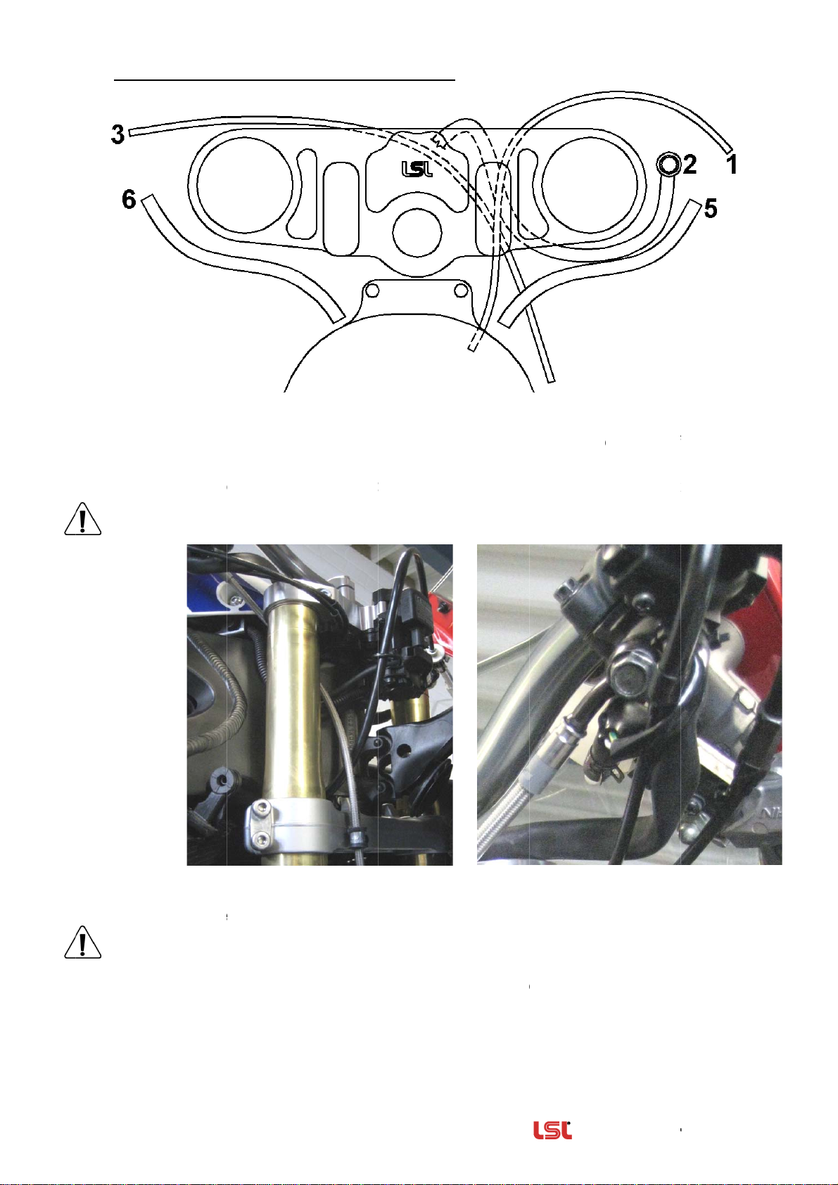
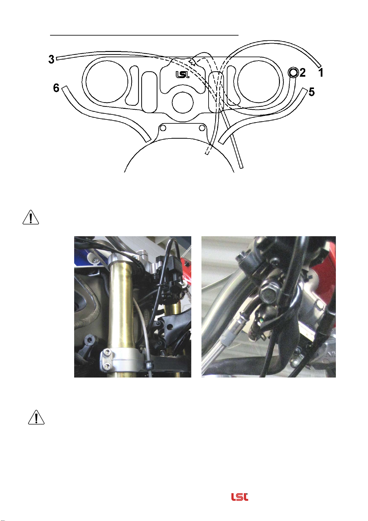
roue avant ! Nous vous conseillons de lire la page 3 pour faciliter la pose des câbles et
durits. Remplacez le té de fourche d’origine par le té de fourche du kit Street-Bike. Montez le
contacteur d’allumage au té de fourche avec les entretoises (l=17mm) et les nouvelles vis
(M8x40). Serrez d’abord l’écrou central à un couple de 15Nm puis les vis de serrage à un couple
de 20Nm.Serrez enfin l’écrou central au couple de serrage indiqué par le fabricant.
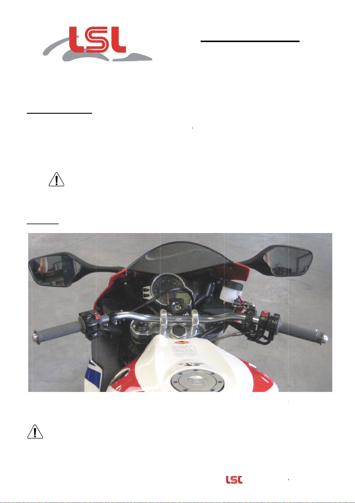
Guidon prescrit: LSL –Street Bike, plat / Type N1
Fixez le nouveau guidon, type N1, dans les pontets. Vissez les vis des pontets de manière
régulière puis serrez à un couple de serrage de 25Nm à la fin du montage.
Limitez la butée de direction!
Afin d’obtenir la liberté de mouvement par
rapport au carénage, limitez la butée de
direction avec la rondelle d’écartement (2mm).
Collez-la sur la butée d’origine avec une colle
appropriée.
Soulever le carénage:Remplacez la vis de
fixation arrière du rétroviseur par la vis M6x35
du kit et posez la rondelle caoutchouc
Ø6xØ25x6.
Dévissez le carénage et posez la rondelle
caoutchouc (Ø8xØ30x7) entre le support et le
carénage. Fixez avec la vis du kit M5x25.
Fixez et ajustez provisoirement les poignées et
commutateurs au guidon et remontez le
carénage latéral. Afin d’obtenir une liberté de
mouvement suffisante pour commutateurs
et leviers, il est nécessaire d’utiliser des
embouts de guidon (N°art.: 135-004.. ou 135-
001A..) et de monter les commutateurs, les
leviers et les poignées vers l’extérieur. Les
poignées doivent dépasser les extrémités
du guidon.
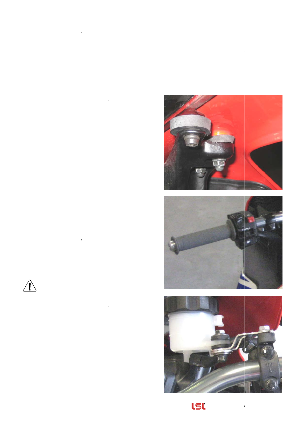
Montez la poignée des gaz de façon à ce que
les câbles montrent vers le bas. Laissez
25mm d’espace entre les commutateurs et
les leviers de frein et d’embrayage.
En cas de frein dépressurisé, contrôlez s’il
est possible de tirer le levier de frein
jusqu’à la poignée sans toucher les
commutateurs! (Pour cela, desserrez un étrier
et faites-le basculer pour pousser les pistons).
Remplacez le support du réservoir de
liquide de frein par celui du kit et fixez-le avec
les vis d’origine. Vissez le réservoir au support
avec l’entretoise Ø11,7x2,75x3,8 et la rondelle
M6 (voir ).
Contrôlez la liberté de mouvement par
rapport au carénage et au réservoir
d’essence avant le serrage définitif des vis.
Ajustez, si nécessaire.
Effectuez les perçages nécessaires aux
fixations. Collez la poignée gauche ave une
colle appropriée.
Ø8xØ30x7 & M5x25
Ø6xØ25x6 & M6x35

————————————— Equipements et Accessoires d'origines ——
Rev. 01 08/07/2011 Page 3 sur 3
Schéma de pose des câbles et flexibles :
Câbles des gaz (1): Pose comme à l’origine. Montez la poignée des gaz de manière à ce que les
câbles partent vers le bas. Contrôlez la liberté de mouvement pendant le braquage gauche/droite.
Durit de frein (2): Montez la durit de frein au maître cylindre de frein et le fixer au té de fourche
inférieur avec un collier, comme indiqué ci-dessous. Tenez compte des instructions de
montage des durits de frein tressées inox, ci-joint.
Câble d’embrayage (3): Utilisez le nouveau câble. Pose comme à l’origine.
Câbles électriques (5 + 6): Pose derrière les bras de fourche.
Contrôlez que câbles ou flexibles soient posés sans tensions ni pliures pendant le
braquage gauche/droite.

Table of contents
Languages:
Other LSL Motorcycle Accessories manuals
Popular Motorcycle Accessories manuals by other brands

SW-Motech
SW-Motech GPT.07.904.65100/B Mounting instructions

hepco & becker
hepco & becker 42123544 00 01 quick start guide

Heat Demon
Heat Demon 210008 instructions

Sealey
Sealey SWH199 instructions

Parkside
Parkside 409157 2207 Operation and safety notes translation of the original instructions

hepco & becker
hepco & becker 650.2514 00 01 Mounting instructions