LSL PC19 Install guide

LSL-Motorradtechnik GmbH • D-47809 Krefeld
www.lsl.eu
Rev. 01 19/10/2011 Seite 1 von 2
Anbaukarte Superbike-Lenkerkit Art.-Nr.: 120H017
Modell: Honda CBR 600F / VFR 750 Baujahr: ´87 - ´90 / ´86 - ´87
Typ: PC19 / PC23 / RC24
Wichtig: Wenn Sie kein ausgebildeter Mechaniker sind, wenden Sie sich bitte an eine
Fachwerkstatt. Beachten Sie grundsätzlich die allgemeine Montageanleitung zur
Montage der Superbike-Lenkerkits.
Lenker: Typ 01 (A01 / L01)
Kürzel für Verlegung d. Züge: Lage der Züge in Fahrtrichtung
vor dem Standrohr V rechts vom Steuerkopf R
hinter dem Standrohr H links vom Steuerkopf L
Verlegung: Längen:
Gaszug: H / R original
Kupplungszug: H / L original
Bremsschlauch: original 36cm (36AB)
Chokezug: H / L original
Die Verkleidung und Verkleidungsscheibe müssen gekürzt werden!
Besonderheiten:
Die Griffarmaturen 1cm vom Lenkerende einrücken. Gaszüge parallel zum Lenker nach
innen führen und mit Kabelbinder am Lenker fixieren. Die Züge zwischen Tank und Rahmen
nach hinten führen.

LSL-Motorradtechnik GmbH • D-47809 Krefeld
www.lsl.eu
Rev. 01 19/10/2011 Seite 2 von 2
Allgemeine Montageanleitung für Superbike-Lenker
1.) Um Beschädigungen zu vermeiden und später die Züge neu verlegen zu können, muß als
erstes der Tank entfernt werden. Zur Sicherheit der elektrischen Systeme sollte die
Batterie am Minuspol abgeklemmt werden.
2.) Griffarmaturen, Bedienungsarmaturen und Hydraulikzylinder vom Lenker demontieren.
Originallenker entfernen.
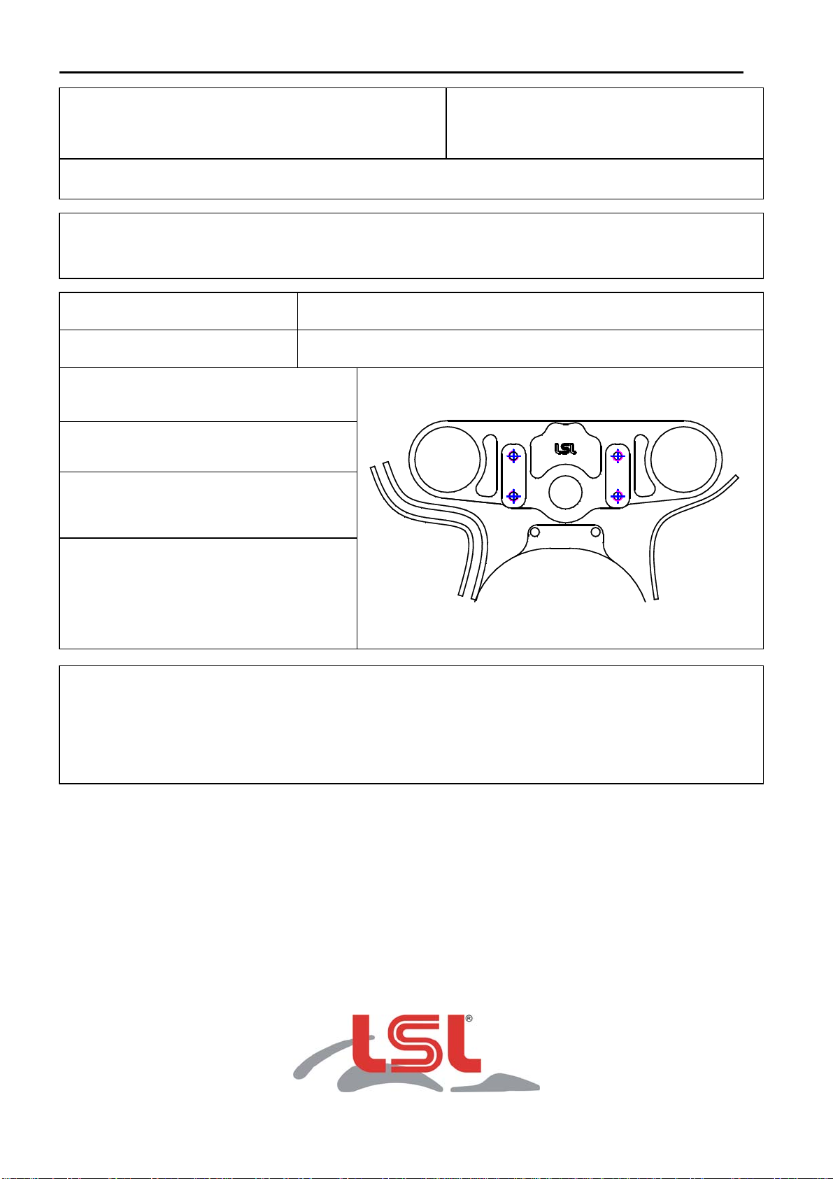
3.) Adaptersystem auf der Gabelbrücke montieren bzw. Originalgabelbrücke gegen die
Superbike-Gabelbrücke austauschen. Zur Demontage des Zündschlosses müssen die
Köpfe der Abreißschrauben aufgebohrt werden. Zündschloß mit beiliegenden Buchsen und
neuen Schrauben an der Gabelbrücke montieren. Nach dem Austausch der Gabelbrücke
sollte der Innensechskant der Befestigungsschrauben des Zündschloßes zur
Diebstahlsicherung ausgebohrt werden. Bei Modellen, an denen die zentrale
Verschraubung gelöst wurde, diese mit dem angegebenen Drehmoment des Herstellers
wieder festziehen. Neuen Lenker mit den Klemmböcken lose montieren. Wenn nötig
Gaszüge neu verlegen.
Beachten Sie bitte die umseitig aufgeführten "Modellbezogene Hinweise zur Montage".
4.) Wenn neue Bremsleitungen im Lieferumfang enthalten sind, wie folgt vorgehen:
Bremshydraulikleitung abbauen. Vorsicht: Bremsflüssigkeit darf nicht auf Lackteile
tropfen! Mitgelieferte Bremsleitung mit neuen Dichtringen montieren.
Montage der Bremsleitung und das Entlüften der Bremsanlage sollte von einer
autorisierten Fachwerkstatt durchgeführt werden. Beachten Sie unbedingt die
separat beiliegende Anbauanleitung der Stahlflex-Bremsleitung.
5.) Nun die Griffarmaturen auf dem Lenker befestigen und ausrichten. Bei LSL-Lenkern die zur
Fixierung nötigen Bohrungen setzen. Stellen Sie sicher, dass kein Kabel oder Schlauch
abgeknickt wird und Kabel bzw. Schläuche spannungsfrei verlegt sind. Kontrollieren sie
auch den Freigang zum Tank hin, dazu evtl. Tank wieder aufsetzen. Lenkerklemmböcke
gleichmäßig anziehen und mit Anzugsmoment 25 Nm festziehen. Das linke Griffgummi mit
einem geeigneten Klebstoff verkleben.
6.) Gegebenenfalls Verkleidungshalter Tank/Rückspiegel entfernen. Wenn erforderlich
Verkleidung und Scheibe so weit kürzen, daß bei Rechts- und Linkseinschlag genügend
Freiraum für Hydraulikzylinder und Hebel entsteht (Siehe Anbaukarte!). In wenigen Fällen
muss der Lenkanschlag mittels beiliegender Distanzscheiben begrenzt werden. Diese
Scheiben sind mit speziellem Klebstoff aus dem Fachhandel auf den originalen
Lenkanschlag zu kleben. Gaszüge bei voll eingeschlagener Lenkung auf Leichtgängigkeit
prüfen.
7.) Der Hochlenkerumbau ist nun korrekt montiert. Bitte vergessen Sie nicht, das Motorrad mit
dem modellbezogenen Datenblatt bei einer anerkannten Prüfstelle vorzuführen und den
Umbau in die Fahrzeugpapiere eintragen zu lassen.
Wir wünschen Ihnen viel Freude beim Fahren!

LSL-Motorradtechnik GmbH • D-47809 Krefeld
www.lsl.eu
Rev. 01 14/03/2013 Page 1 of 2
Fitting instruction Superbike-Kit
P/N: 120H017
Model: Honda CBR 600F / VFR 750 Year: ´87-´90 / ´86-´87
Type: PC19 & PC23 / RC24
Important: If you are not a trained motorcycle mechanic stop now. Ask a local
motorcycle shop to do the work for you. Please read the LSL-Superbike-Kit
Fitting instructions.
Recommended bar: Type 01 (A01 / L01)
Length of brake-lines: 36 cm (36AB)
Code for cable routing: Position of cable from riders position
in front of the fork F right from steering head R
behind the fork B left from steering head L
Throttle cable: B / R
Clutch cable: B / L
Choke cable: B / L
Fairing and screen need to be cut. A Superbike-Screen is available.
Instructions:
Fit the handlebar grips about 1cm away from the end of the handlebar. Lead the
throttle cables along the handlebar and in the following between fuel tank and frame
to the carburettor-unit. Fix the cable s with straps to the handlebar.

LSL-Motorradtechnik GmbH • D-47809 Krefeld
www.lsl.eu
Rev. 01 14/03/2013 Page 2 of 2
LSL–Superbike-Kit Fitting Instructions
1.) To avoid scratches and dents when re-routing hoses and cables remove the gas tank first.
Remove fairing bracket and mirrors if necessary. Always disconnect battery ground
before working on electric wiring and switches!
2.) Remove handlebar controls, clutch lever bracket and brake cylinder assy, then remove the
original handlebar.
3.) Mount the adaptor on standard top yoke (or swap new yoke depending on kit type). To
demount the ignition lock you mostly have to drill out the heads of the breakaway screws.
After mounting the ignition lock with the attached bushings and new screws at the LSL-yoke
you have to drill out the heads of the screws as theft protection, if your bike is not equipped
with an immobilizer. If the crown nut had to be removed tighten up to original torque. Mount
the new handlebar without tightening the screws of the clamps too strong. Re-route cables
and hoses if necessary. Please refer to "specific mounting instructions" for re-routing.
4.) Remove brake-hose(s). Caution: avoid brake fluid on painted surfaces! Mount enclosed
brake-hose(s) with new gaskets.
Caution: Any work on the brake system or bleeding the system should be done by an
authorized dealer or a qualified mechanic! Pump brake lever until proper pressure is
felt on lever. Test brakes at slow speed!
5.) Now mount the handlebar controls and clutch/brake assy. Set drillings to fix controls on the
handlebar. If other than LSL handlebars are chosen, use tapes or metal sheets under the
controls to fix them on the handlebar. Now tighten handlebar clamps equally up to 25Nm /
18.4lbf ft torque. Make sure that no cable is bended and stays tension-free when turning
the handlebar.
6.) Shorten fairing and screen, if necessary, to allow full steering movement of handlebar with
sufficient space at levers and switches. Please refer to "specific mounting instructions" for
shortening. Check throttle, choke and clutch cables function and clearance on left and right
steering angle. Adjust or re-route if necessary. After finishing check all connections.
7.) Always check local laws and your manufacturer’s warranty conditions for using aftermarket
parts on your bike!
Ride safe and have fun!

LSL-Motorradtechnik GmbH • D-47809 Krefeld
www.lsl.eu
Rev. 01 14/03/2013 Page 1 sur 2
Fiche de montage pour kit Street Bike No. Article: 120H017
Modèle: Honda CBR 600F
Modèle: Honda VFR 750F Année: 1987 - 1990
Année: 1986 - 1987
Châssis: PC19/23 (CBR 600F) & RC24 (VFR 750F)
Important: Le montage doit être fait par un professionnel. Veuillez respecter les
conseils pratiques pour le montage des kits Street Bike.
Guidon prévu : Type 01 (A01 / L01)
Durite de frein : 36cm (36AB)
Position des câbles dans le sens de la
marche:
(1)
(2)
(3)
Câble de gaz (1): derrière le tube de fourche
et à droite de la colonne de direction
Câble / Durite d’embrayage (2): derrière le
tube de fourche et à gauche de la colonne de
direction
Câble de starter (3): derrière le tube de
fourche et à gauche de la colonne de
direction
Particularités:
Enfoncer les poignées à 1cm des extrémités.
Passer les câbles de gaz entre le cadre et le réservoir d’essence vers l’arrière.

LSL-Motorradtechnik GmbH • D-47809 Krefeld
www.lsl.eu
Rev. 01 14/03/2013 Page 2 sur 2
Directives de principe pour le montage des kits Street Bike
1.) Supprimez le réservoir d’essence afin d’éviter tout endommagement et pour faciliter la
repose des câbles. Par mesure de sécurité, défaire le fil du pôle négatif de la batterie.
2.) Démontez les leviers et le maître cylindre hydraulique. Enlevez le guidon d’origine.
3.) Fixez le système d’adaptation au té de fourche ou alors changez le té de fourche
d’origine contre le té de fourche pour Street Bike. Pour la dépose du contacteur
d’allumage, percez les têtes des vis de fixation. Posez le contacteur d’allumage au té de
fourche avec les entretoises et les nouvelles vis contenues dans le kit. Percez les têtes
des vis comme sécurité contre le vol. Si le vissage central a été desserré, le resserrer
au couple de serrage indiqué par le fabricant. Posez les pontets et le nouveau guidon et
fixez les bracelets sans les serrer. Reposez les câbles d’accélérateur, si nécessaire.
Tenez compte des directives de montage suivant le type de moto.
4.) Si le kit contient de nouvelles durites de frein, procédez comme suit :
Démontez la conduite du maître cylindre de frein hydraulique.
Attention : le liquide pour freins ne doit pas tomber sur les parties peintes! Fixez la
nouvelle durite de frein en utilisant des joints neufs.
Le montage des durites de frein et la purge du système de frein doivent être
effectués par un professionnel. Tenir compte des instructions de montage des
durites tressées inox en annexe.
5.) Fixez les leviers au guidon et ajustez-les. Sur les guidons LSL, placez les
perçages nécessaires à la fixation. Contrôlez que câbles ou tuyaux soient posés sans
tensions ni pliures. Contrôlez le braquage gauche /droite par rapport au réservoir
d’essence. Serrez les bracelets de manière régulière jusqu’à un couple de 20 Nm.
Collez la poignée gauche avec une colle appropriée.
6.) S’il existe, supprimez le support de carénage entre le réservoir d’essence/rétroviseur.
Si nécessaire, raccourcissez la tête de fourche et la bulle pour qu’il reste suffisamment
d’espace pour le levier et le maître cylindre pendant le braquage gauche/droite (voir
fiche de montage). Dans certains cas la butée doit être limitée par les rondelles
d’écartement incluses dans le kit. Collez ces rondelles sur les butées d’origine avec une
colle spéciale. Contrôlez le fonctionnement des câbles d’accélérateur pendant le
braquage gauche/droite.
7.) Respectez les règlements par rapport à l’enregistrement des accessoires dans les
papiers de la moto.
This manual suits for next models
2
Table of contents
Languages:
Other LSL Motorcycle Accessories manuals