manuals.online logo
Brands
  1. Home
  2. •
  3. Brands
  4. •
  5. LSL
  6. •
  7. Motorcycle Accessories
  8. •
  9. LSL 377-545SW User manual

LSL 377-545SW User manual

1
Motorschutzbügel/ Engine guard
1120
1 Engine guard left black
1 Engine guard right black
Screw kit:
2 VA - allen screw M10 x 80mm
1 VA - allen screw M12 x 110mm
1 VA - allen screw M12 x 90mm
1 allen screw M12 x 330mm
2 VA - washer ø10,5
4 VA - washer ø12,5
1 self-lock nut M12
3 steel spacer ø25 x ø17 x 50mm
1 steel spacer ø25 x ø17 x 35mm
1 steel spacer ø20 x ø14 x 53mm
1 steel spacer ø20 x ø14 x 56mm
1 Motorschutzbügel links schwarz
1 Motorschutzbügel rechts schwarz
Schraubensatz:
2 VA - Zylinderkopfschraube M10 x 80mm
1 VA - Zylinderkopfschraube M12 x 110mm
1 VA - Zylinderkopfschraube M12 x 90mm
1 Zylinderkopfschraube M12 x 330mm
2 VA - U-Scheibe ø10,5
4 VA - U-Scheibe ø12,5
1 selbstsichernde Mutter M12
3 Stahldistanz ø25 x ø17 x 50mm
1 Stahldistanz ø25 x ø17 x 35mm
1 Stahldistanz ø20 x ø14 x 53mm
1 Stahldistanz ø20 x ø14 x 56mm
BMW R nine T Scrambler 2016-
BMW R nine T Pure/Racer/Urban G/S 2017-
BMW R nine T 2014-
Artikel Nr.: / Item-no.:
377-545SW schwarz/black
INHALT
CONTENTS
Ratsche/Ratchet
Verlängerung/extension
Set
BENÖTIGTE WERKZEUGE
TOOLS REQUIRED
2
Of course, the assembly requires a certain technical experience. If you are not sure how to execute a determined
action, you should ask your local distributor to do it. First, tighten all screws only loosely. After mounting all parts,
the screws should be tightened to the torque specified. This guarantees, that the product is mounted without
tension. Observe the tightening torques of the manufacturer! Control all screw connections after the assembling for
tightness!
Die Voraussetzung für die Montage ist natürlich eine gewisse technische Erfahrung. Wenn Sie sich nicht sicher sind,
wie man eine bestimmte Arbeit ausführt, sollten Sie diese Ihrer Fachwerkstatt überlassen. Ziehen sie alle
zugänglichen Schrauben zuerst nur locker an. Nachdem alles montiert ist, werden die Schrauben dann auf das
entsprechende Anzugsmoment festgezogen. Dadurch wird sichergestellt, dass das Produkt spannungsfrei angebaut
ist. Anzugsmomente beachten! Nach der Montage alle Verschraubungen auf festen Sitz kontrollieren!
Beachten Sie die in Ihrem Land geltenden Zulassungsbestimmungen.
Für den Bereich der BRD gilt: Ein Eintrag in die Fahrzeugpapiere ist nicht erforderlich.
2
1
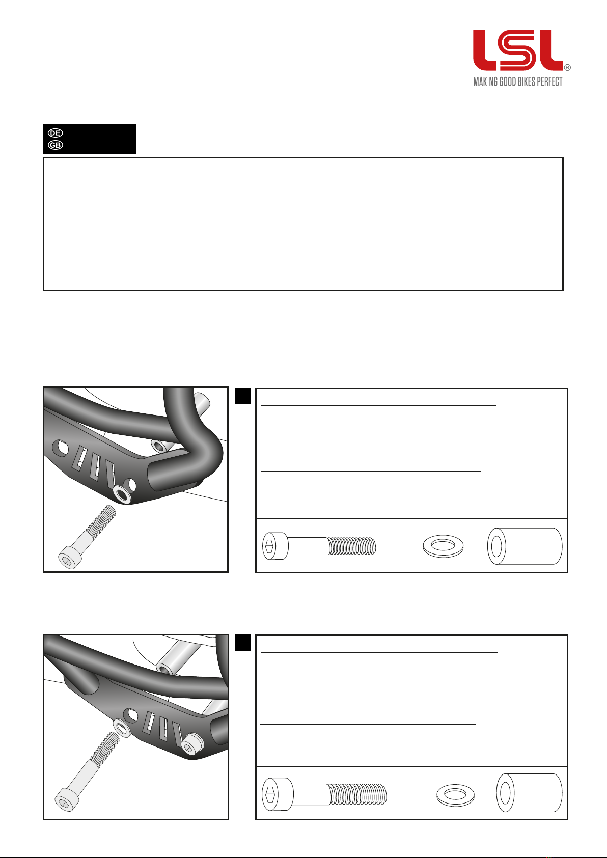
Montage des Motorschutzbügels rechts unten vorne:
Montage des Motorschutzbügels rechts unten hinten:
Die Originalschraube demontieren; sie entfällt. Befestigung am nun
freien Gewinde der unteren Motorhalterung. Die Stahldistanz ø25 x
ø17 x 35mm in den Rahmen einsetzen. Die Verschraubung erfolgt
mit der Zylinderkopfschraube M12 x 90 und U-Scheibe ø12,5.
am freien Gewinde. Die Stahldistanz ø20 x ø14 x 53mm zwischen
Motorschutzbügel und Motor einfügen. Die Verschraubung erfolgt
mit der Zylinderkopfschraube M10 x 80 und U-Scheibe ø10,5.
1x 1x
1x 1x 1x
1x
Fastening of the engine guard right bottom rear:
Dismantle original screw - it is obsolete. Fastening at the now free
thread. Add steel spacer ø25 x ø17 x 35mm between engine guard
and engine block. Use allen screw M12 x 90 with washer ø12,5.
Fastening of the engine guard right bottom front:
at the free thread. Add steel spacer ø20 x ø14 x 53mm between
engine guard and engine block. Use allen screw M10 x 80 with
washer ø10,5.
Motorschutzbügel/ Engine guard
WICHTIG
IMPORTANT
3
3
Montage des Motorschutzbügels rechts oben:
Die Originalschraube demontieren; sie entfällt.
5
4
Montage des Motorschutzbügels links unten vorne:
Montage des Motorschutzbügels links unten hinten:
Die Originalschraube demontieren; sie entfällt. Befestigung am
nun freien Gewinde der unteren Motorhalterung. Die Stahldistanz
ø25 x ø17 x 50mm in den Rahmen einsetzen. Die Verschraubung
erfolgt mit der Zylinderkopfschraube M12 x 110 und U-Scheibe
am freien Gewinde. Die Stahldistanz ø20 x ø14 x 56mm zwischen
Motorschutzbügel und Motor einfügen. Die Verschraubung erfolgt
mit der Zylinderkopfschraube M10 x 80 und U-Scheibe 10,5.
An der oberen Motoraufhängung die Stahldistanz ø25 x ø17 x
50mm in den Rahmen einsetzen und die Zylinderkopfschraube
M12 x 330 mit U-Scheibe ø12,5 (von rechts) durchführen.
1x
1x
1x
Fastening of the engine guard right top:
Dismantle original screw - it is obsolete.
at the top engine support. Add steel spacer ø25 x ø17 x 50mm in
the boring of the frame. Use allen screw M12 x 330 with washer ø12,5.
Fastening of the engine guard left bottom front:
at the free thread. Add steel spacer ø20 x ø14 x 56mm between
engine guard and engine block. Use allen screw M10 x 80 with
washer ø10,5.
Fastening of the engine guard left bottom rear:
Dismantle original screw - it is obsolete. Fastening at the now free
thread. Add steel spacer ø25 x ø17 x 50mm between engine guard
and engine block. Use allen screw M12 x 110 with washer ø12,5.
1x 1x 1x
1x 1x 1x
Motorschutzbügel/ Engine guard
MONTAGEANLEITUNG
MOUNTING INSTRUCTIONS
4
6
Montage des Motorschutzbügels links oben:
An der oberen Motoraufhängung die Stahldistanz ø25 x ø17 x
50mm in den Rahmen einsetzen und mit dem Gewinde der in
Schritt 3 montierten Zylinderkopfschraube M12 x 330 verschrauben.
U-Scheibe ø12,5 und eine selbstsichernde Mutter M12 verwenden.
1x 1x
1x
Fastening of the engine guard left top:
Add steel spacer ø25 x ø17 x 50mm in the boring of the frame.
Secure the allen screw M12 x 330, mounted in step 3, with
washer ø12,5 and self lock nut M12.
Motorschutzbügel/ Engine guard
MONTAGEANLEITUNG
MOUNTING INSTRUCTIONS

Other LSL Motorcycle Accessories manuals

LSL PC19 Install guide

LSL

LSL PC19 Install guide

LSL 153T072R Install guide

LSL

LSL 153T072R Install guide

LSL 506Y017A Install guide

LSL

LSL 506Y017A Install guide

LSL 153T055R Install guide

LSL

LSL 153T055R Install guide

LSL SC59 Install guide

LSL

LSL SC59 Install guide

LSL 556KT07 Series Install guide

LSL

LSL 556KT07 Series Install guide

LSL 377-705SW User manual

LSL

LSL 377-705SW User manual

LSL 150A022 Install guide

LSL

LSL 150A022 Install guide

LSL CB1100A Install guide

LSL

LSL CB1100A Install guide

LSL 245BT69SI Install guide

LSL

LSL 245BT69SI Install guide

LSL 506Y141A Install guide

LSL

LSL 506Y141A Install guide

LSL CLASSIC 555T109-Gv Technical manual

LSL

LSL CLASSIC 555T109-Gv Technical manual

LSL K12R Install guide

LSL

LSL K12R Install guide

LSL 150S127 Install guide

LSL

LSL 150S127 Install guide

LSL ERGONIA Installation instructions

LSL

LSL ERGONIA Installation instructions

LSL 377-805SW User manual

LSL

LSL 377-805SW User manual

LSL Superbike-Kit Install guide

LSL

LSL Superbike-Kit Install guide

LSL 506Y139A Install guide

LSL

LSL 506Y139A Install guide

LSL 140T031 Install guide

LSL

LSL 140T031 Install guide

LSL 110B058 Install guide

LSL

LSL 110B058 Install guide

LSL 130Y108 Install guide

LSL

LSL 130Y108 Install guide

LSL 150T064 Install guide

LSL

LSL 150T064 Install guide

LSL 377-550SW User manual

LSL

LSL 377-550SW User manual

LSL 153T072H Install guide

LSL

LSL 153T072H Install guide

Popular Motorcycle Accessories manuals by other brands

hepco & becker 6609516 01 01 quick start guide

hepco & becker

hepco & becker 6609516 01 01 quick start guide

KTM Power Parts 72035936000 manual

KTM Power Parts

KTM Power Parts 72035936000 manual

Nolan N64 Safety and instructions for use

Nolan

Nolan N64 Safety and instructions for use

DYNATEK DFS1-10 User instructions

DYNATEK

DYNATEK DFS1-10 User instructions

Dynojet Power commander V installation instructions

Dynojet

Dynojet Power commander V installation instructions

Caberg just speak quick start guide

Caberg

Caberg just speak quick start guide

Ohlins 225 TM owner's manual

Ohlins

Ohlins 225 TM owner's manual

Ducati PERFORMANCE 979000152 manual

Ducati

Ducati PERFORMANCE 979000152 manual

Ruckus Wireless PWJDM installation guide

Ruckus Wireless

Ruckus Wireless PWJDM installation guide

Ventura Bike-Pack System instructions

Ventura

Ventura Bike-Pack System instructions

Big Bike Parts 52-949 installation instructions

Big Bike Parts

Big Bike Parts 52-949 installation instructions

Lone Rider PACCUBE Care Instructions

Lone Rider

Lone Rider PACCUBE Care Instructions

MRA 4025066170395 Mounting instructions

MRA

MRA 4025066170395 Mounting instructions

rizoma ZBW060A user manual

rizoma

rizoma ZBW060A user manual

Caberg EGO quick start guide

Caberg

Caberg EGO quick start guide

Malossi 5519025 manual

Malossi

Malossi 5519025 manual

GÜDE GFH PRO Translation of original operating instructions

GÜDE

GÜDE GFH PRO Translation of original operating instructions

Wilbers 303 Installation and operation manual

Wilbers

Wilbers 303 Installation and operation manual

manuals.online logo
manuals.online logoBrands
  • About & Mission
  • Contact us
  • Privacy Policy
  • Terms and Conditions

Copyright 2025 Manuals.Online. All Rights Reserved.