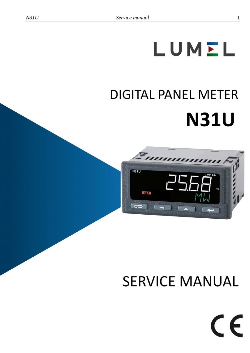
Lumel N21 User manual

1
PANEL MOUNTED METER
N21
USER’S MANUAL

2

3
Contents
1. APPLICATION AND METER DESIGN.............................................. 5
2. METER SET .......................................................................... 6
3. BASIC REQUIREMENTS, OPERATIONAL SAFETY .............................. 6
4. INSTALLATION ...................................................................... 8
4.1. Mounting ....................................................................... 8
4.2. External Connection Diagrams ............................................. 9
5. SERVICE............................................................................. 11
5.1 Display description........................................................... 11
5.2 Power-on status indication.................................................. 11
5.3 Device configuration using e-Con program...............................12
5.3.1 Configuration parameters................................................. 14
5.3.2 Alarm output operating modes...........................................18
5.3.3 Individual characteristic .................................................. 20
5.3.4 BArgraph configuration.................................................... 21
5.3.5 Preview of the measuring values........................................ 23
5.3.6 Editor of the measuring unit.............................................. 23
6. CONFIGURATION INTERFACE.................................................... 25
6.1 USB Interface – list of parameters ......................................... 25
6.2 Map of N21 meter registers ................................................. 25
7. ERROR CODES ..................................................................... 32
8. SOFTWARE UPDATE .............................................................. 34
9. TECHNICAL DATA.................................................................. 36
10. ORDERING CODE................................................................. 40

4

5
1. APPLICATION AND METER DESIGN
The N21 meter is a digital programmable panel mounted instrument
designed to measure d.c. voltages or d.c. currents: unipolar or bipolar,
temperature with use of thermocouples J (Fe-CuNi), K (NiCr-NiAl)
and Pt100 resistance thermometers. The readout field is an OLED
graphic display with a resolution of 32x128 points.
The eCon program is designed for the configuration of the N21 meter.
The meter should be connected to a PC via a miniUSB connector
located on the rear of the meter. Following parameters can be set:
• measuring input
• display precision of the result (decimal point)
• relay output operating mode
• thresholds triggering the relay output
• time delays of the relay output triggering
• individual characteristic for measuring signal
• automatic or manual temperature compensation of cold junctions
• averaging time of the measurement
• user-defined units of measured signal
• display language
• bargraph configuration.
Meter output signals are isolated from the input signals and power supply.
Figure 1. View of the meter
a) horizontal b) vertical

6
2. METER SET
Complete set of the meter includes:
- N21 meter.................................................. 1 pc
- clamps to fix in the panel......................... 4 pcs
- seal............................................................ 1 pc
- user’s manual............................................ 1 pc
- guarantee card .......................................... 1 pc
3. BASIC REQUIREMENTS,
OPERATIONAL SAFETY
The symbols in the manual mean:
Warning!
Warning of potentially hazardous situations. Especially
important to be aware of before connecting the device.
Failure to follow the directions marked by this symbol
could result in serious injuries of the personnel and dama-
ge of the device.
Caution!
Useful notes. The notes should facilitate the operation
of the device. Should pay attention, if the device is not
working as expected.
Possible consequences in case of ignoring informa-
tion!
Accessories:
For the N21 meter you can order:
– USB CABLE A/miniUSB-B - 1m BLACK; Order code 20-069-00-
00150.

7
In terms of operational safety the meter meets the requirements
of the EN 61010-1 standard.
Comments concerning safety:
• Assembly and installation of the electrical connections should be
made only by people authorized to perform assembly of electric
devices.
• The person installing the meter is responsible for ensuring
the safety of the implemented system.
• Always check the connections before turning the meter on.
• Opening the meter housing gives access to the live parts.
The supply must be switched off and the measuring circuits discon-
nected before removing the meter housing.
• Removal of the meter housing cover during the warranty period
voids the warranty.
• The meter is designed to be installed and used in the industrial
electromagnetic environment conditions.
• The building installation should have a switch or a circuit-breaker
installed. This switch should be located near the device, easy
accessible by the operator and suitably marked.
• In case of damage, the meter can to repaired only by manufacturer’s
authorized service.
• Check the correct operation of the meter before it is used for mea-
suring after a repair.
• Connection and/or using the meter in a way which is not compliant
with the user’s manual, may cause deterioration of the degree
of protection.

8
Figure 2. Meter fitting
Figure 3. Meter dimensions
4. INSTALLATION
4.1. Mounting
The N21 meter has separable strips with the screw terminals which
enable the connection of external supply wires of 2.5 mm2and signal
wires of 1.5 mm2.
You must prepare a 92+0,6 x 45+0,6 mm cut-out in the panel. The thi-
ckness of the panel material should not exceed 6 mm. The meter
should be mounted from the panel front with disconnected supply volta-
ge. Check the correct position of the seal before placing the meter into
the panel. When the panel is inserted in the slot, mount it in the panel
with the mounting brackets (Fig. 2).

9
4.2.External Connection Diagrams
USB
conguration
+
measurement signals
24 V d.c.
30 mA max
(supply of object transducers)
alarm 24 V N 230 V
supply
Figure 4. Electrical connections of the N21 meter
Comment concerning safety:
The meter is provided with a universal power supply that allows
operation in a wide range of input voltages 22..253V a.c / 20..300V d.c.
Life-threatening voltage also appears at the terminal 12 of the meter
in the case of the use of the input terminals 13-14.

10
123
456
-+
123
456
-+
current input ±20mA voltage input ±10V
Figure 5. Connections of measuring signals
123
456123
456
Resistance thermometer
in a 2-wire system
Resistance thermometer
in a 3-wire system
123
456
123
456
thermocouple J,K voltage input ±75mV

11
5. OPERATION
5.1.Display description
Figure 6. Front panel
5.2 Power-on status indication
The display shows information about the manufacturer, device type
and software version after switching the supply on. Then the meter starts
to show the measuring values according to the current configuration.
alarm
indicator
user-defined unit
measuring
value
bargraph
USB cable
connection
indicator
a) horizontal version b) vertical version
bargraph
zero
marker
USB cable
connection
indicator
alarm
indicator
indicator
of alarm
thresholds
measuring
value
user-defined
unit

12
5.3. Device configuration using e-Con program
Figure 7. e-Con program window

13
The eCon program designed for configuration of the N21 meter is
available at the manufacturer’s website (www.lumel.com.pl). The meter
should be connected to a PC via USB cable. The drivers are also
available on the manufacturer’s website. After drivers installation a new
serial port appear. When the eCon program starts, select the port on
which the device is installed in the area “Communication”, set the trans-
mission parameters (baud rate 9600, mode RTU 8N2), and then click the
icon “connect”.
Before changing a configuration you should read and save the current
configuration for future restore the settings. You can save the parameters
to a file, read from a file, as well as export the configuration to a pdf file
using the eCon menu (Fig. 8).
Figure 8. Read, write and export settings
Information
about the meter
Export the configuration
to a pdf file
Saving the configuration
to a file
Reading the configuration
from file
Saving the configuration to a meter
Reading the configuration from a meter

14
Figure 9. Establishing connection to N21 meter
5.3.1 Configuration parameters
After establishing a connection, there are configuration parameters
of the meter on the right side of the program window.
Table 1
Connect/
disconnect
Parameter
name Parameter description Range of parameter
change
Range
of
parameter
change
Input Configuration
Measuring
input Type and range
of the input signal Voltmeter +/- 10 V
Millivoltmeter +/- 75 mV
Milliammeter +/- 20 mA
Pt100
thermocouple J
thermocouple K
Voltmeter
+/- 10 V

15
Defining
units
TDesigning
a pictogram
representing the
symbol of measuring
value unit using the
graphical editor.
Designed pictogram
can be uploaded to
the meter or saved to
a file. Figure 14.
Figure 14 V
Precision
of the
displayed
values
Choice of precision
of the displayed
values. Ranges:
0: -99999...99999
0.0: -9999.9...9999.9
0.00: -999.99...999.99
0.000: -99.999...99.999
0
0.0
0.00
0.000
0.0
Averaging
time
Averaging time
of the measurement
results.
0.2 s
0.5 s
1 s
3 s
5 s
10 s
15 s
20 s
0.5 s
Automatic
compensation
Automatic
temperature
compensation of the
thermocouple cold
junctions or a line
resistance for Pt100
sensor.
None
On On
Manual
compensation
It is possible to set
a temperature value,
which will be corrected
by the measurement
result if an automatic
temperature
compensation
of the thermocouple
cold junction or a line
resistance is disabled.
-60.00 ... 60.00 °C 0.00

16
Enabling
individual
characteristic
Enabling the value
of the input signal
conversion
to the displayed value
according to the linear
characteristic of user-
defined coefficients.
Without individual
characteristic
Characteristic enabled
Without
individual
characte-
ristic
Individual
characteristic
(X1,Y1)
User-defined first
point of the individual
characteristic.
Figure 11.
-99999.9..99999.9 X1 = 0,
Y1 = 0
Individual
characteristic
(X2,Y2)
User-defined second
point of the individual
characteristic.
Figure 11.
-99999.9..99999.9 X2 = 1,
Y2 = 1
The lower
bargraph
display range
The measured value
representing 0% of
bargraph display
indications. Point 5.3.4
-99999.9..99999.9 0
The upper
bargraph
display range
The measured value
representing 100%
of bargraph display
indications. Point 5.3.4
-99999.9..99999.9 0
Measuring
values Preview of the current
measuring values Figure 13 -
Output Configuration
Relay output
operating
mode
The method
of triggering the alarm
output depending
on the input signal
alarm thresholds.
The H-OFF mode
disables the output
permanently, H-ON
activates the output
permanently. Other
modes as shown in
Figure 10.
H-OFF
H-ON
N-OFF
N-ON
OFF
ON
H-OFF

17
Low
threshold
triggering
the relay
output
Lower threshold
of the input signal
causing the alarm
output reaction
(AL_L at Fig. 10)
-99999.9..99999.9 60.0
High
threshold
triggering
the relay
output
Upper threshold
of the input signal
causing the alarm
output reaction
(AL_H at Fig. 10)
-99999.9..99999.9 80.0
Relay
activation
delay
Relay activation delay
relating to changes
of the input signal 0 – 3600 s 0
Relay
deactivation
delay
Relay deactivation
delay relating to
changes of the input
signal
0 – 3600 s 0
General Settings
Saving
parameters
to the
memory
Saving actually set
parameters to the
internal non-volatile
memory.
Do not save
Save Do not
save
Language Setting language for
dislpayed messages Polish
English Polish
Set
the default
parameters
Restoring the meter
default conguration
- -
NOTE: The button Save sends the current configuration
to the device N21 and save default settings to non-volatile memory.
In order to change not to apply after connecting and reconnecting the
supply, one needs to turn off the parameter Writing the parameters to
the memory.

18
a) n-on
b) n-off
c) on
5.3.2 Alarm output operating modes
Measured value
Measured value
Measured value
Measured value
Alarm state Alarm state
o
o
o o
o
on
on
on
on on
Measured value
Measured value
Measured value
Measured value
Alarm state Alarm state
Alarm state
Alarm state
o o
o o
o
on
on
on
on on
Measured value
Measured value
Measured value
Measured value
Alarm state Alarm state
Alarm state
Alarm state
o o
o o
o
on
on
on
on on

19
d) off
Figure 10. Relay output operating modes
Measured value
Measured value
Measured value
Measured value
Alarm state
Alarm state
Alarm state Alarm state
o
o
o o
o
on
on
on
on on
e) H-on
always on
f) H-off
always off

20
5.3.3 Individual characteristic
The individual characteristic allows the conversion of the measuring
value (converted by an optional activated individual characteri-
stic) to the displayed value. It is used for imaging the measurements
of non-electrical quantities using non-electrical transducers
to the standard quantities. The conversion is done by an approximation
of a straight line passing through the characteristic parameters points (Fig. 11).
measuring value
value
displayed
Figure 11. Individual characteristic
Example: Pressure transducer with a range of 0-500 Pa and 0-10 V
voltage output is connected to the input voltage range of ± 10 V.
Set the individual characteristic as follows:
X1 – 0 (lower value of the measuring range of the N21 meter)
X2 – 10 (upper value of the measuring range of the N21 meter)
X1 – 0 (lower value of the measuring range of the pressure transducer)
X2 – 500 (upper value of the measuring range of the pressure
transducer)
After enabling the individual characteristic, the meter indicates directly
the value in Pa.
Other manuals for N21
1
Table of contents
Other Lumel Measuring Instrument manuals
Popular Measuring Instrument manuals by other brands

Elma Instruments
Elma Instruments Elma 9200BT manual

Hioki
Hioki CT9691 installation manual

Exotek Instruments
Exotek Instruments MC-60CPA user manual

PCE Americas
PCE Americas PCE-WM 1 manual

Dwyer Instruments
Dwyer Instruments RVM Specifications-installation and operating instructions

ELMETRON
ELMETRON CX-461 user manual

Airmar
Airmar WeatherStation 200WXRS Owner's guide & installation instructions

Qu-Bit Electronix
Qu-Bit Electronix EON manual

Velleman
Velleman DVM8080 user manual

KROHNE
KROHNE OPTIMASS 1000 Series Guidelines for use

Simpson
Simpson S664 Operation manual

Cleveland Controls
Cleveland Controls 6650 instruction manual