manuals.online logo
Brands
  1. Home
  2. •
  3. Brands
  4. •
  5. Lumel
  6. •
  7. Measuring Instrument
  8. •
  9. Lumel NA6 User manual

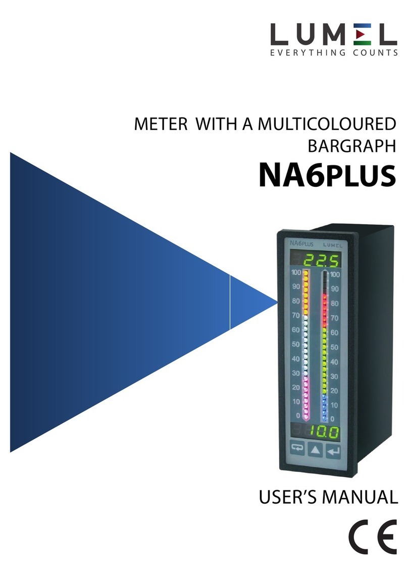
Lumel NA6 User manual

Other manuals for NA6

1

Other Lumel Measuring Instrument manuals

Lumel N20HPLUS User manual

Lumel

Lumel N20HPLUS User manual

Lumel N43 User manual

Lumel

Lumel N43 User manual

Lumel N43 User manual

Lumel

Lumel N43 User manual

Lumel N31U User manual

Lumel

Lumel N31U User manual

Lumel NR30PNET User manual

Lumel

Lumel NR30PNET User manual

Lumel NA6 User manual

Lumel

Lumel NA6 User manual

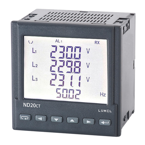
Lumel ND20CT User manual

Lumel

Lumel ND20CT User manual

Lumel N21 User manual

Lumel

Lumel N21 User manual

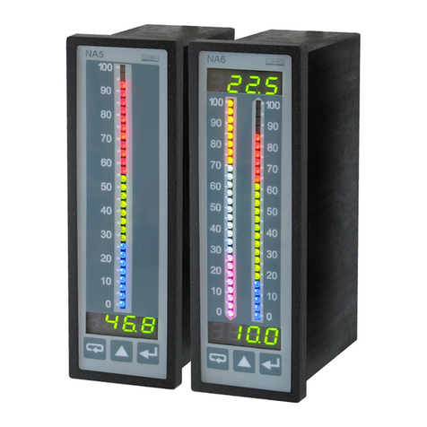
Lumel NA5 Series User manual

Lumel

Lumel NA5 Series User manual

Lumel NA5 Series User manual

Lumel

Lumel NA5 Series User manual

Lumel N32O User manual

Lumel

Lumel N32O User manual

Lumel NA3 User manual

Lumel

Lumel NA3 User manual

Lumel N100 User manual

Lumel

Lumel N100 User manual

Lumel KS5 User manual

Lumel

Lumel KS5 User manual

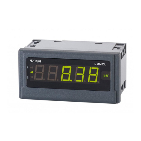
Lumel N20PLUS User manual

Lumel

Lumel N20PLUS User manual

Lumel NA5 Series User manual

Lumel

Lumel NA5 Series User manual

Lumel N10 User manual

Lumel

Lumel N10 User manual

Lumel N30U User manual

Lumel

Lumel N30U User manual

Lumel NA5PLUS User manual

Lumel

Lumel NA5PLUS User manual

Lumel N14 User manual

Lumel

Lumel N14 User manual

Lumel ND30 User manual

Lumel

Lumel ND30 User manual

Lumel N100 User manual

Lumel

Lumel N100 User manual

Lumel N24S User manual

Lumel

Lumel N24S User manual

Lumel NMID30-2 User manual

Lumel

Lumel NMID30-2 User manual

Popular Measuring Instrument manuals by other brands

Powerfix Profi 278296 Operation and safety notes

Powerfix Profi

Powerfix Profi 278296 Operation and safety notes

Test Equipment Depot GVT-427B user manual

Test Equipment Depot

Test Equipment Depot GVT-427B user manual

Fieldpiece ACH Operator's manual

Fieldpiece

Fieldpiece ACH Operator's manual

FLYSURFER VIRON3 user manual

FLYSURFER

FLYSURFER VIRON3 user manual

GMW TG uni 1 operating manual

GMW

GMW TG uni 1 operating manual

Downeaster Wind & Weather Medallion Series instruction manual

Downeaster

Downeaster Wind & Weather Medallion Series instruction manual

Hanna Instruments HI96725C instruction manual

Hanna Instruments

Hanna Instruments HI96725C instruction manual

Nokeval KMR260 quick guide

Nokeval

Nokeval KMR260 quick guide

HOKUYO AUTOMATIC UBG-05LN instruction manual

HOKUYO AUTOMATIC

HOKUYO AUTOMATIC UBG-05LN instruction manual

Fluke 96000 Series Operator's manual

Fluke

Fluke 96000 Series Operator's manual

Test Products International SP565 user manual

Test Products International

Test Products International SP565 user manual

General Sleep Zmachine Insight+ DT-200 Service manual

General Sleep

General Sleep Zmachine Insight+ DT-200 Service manual

Sensa Core Lacto Spark user manual

Sensa Core

Sensa Core Lacto Spark user manual

VOLTCRAFT UTS-1980 operating instructions

VOLTCRAFT

VOLTCRAFT UTS-1980 operating instructions

EBCHQ 94915 Operation manual

EBCHQ

EBCHQ 94915 Operation manual

Balluff BIP LD2-T017-01-EP-S4 Series user guide

Balluff

Balluff BIP LD2-T017-01-EP-S4 Series user guide

Pulsar IMP Lite Series instruction manual

Pulsar

Pulsar IMP Lite Series instruction manual

ETCR 6800 user manual

ETCR

ETCR 6800 user manual

manuals.online logo
manuals.online logoBrands
  • About & Mission
  • Contact us
  • Privacy Policy
  • Terms and Conditions

Copyright 2025 Manuals.Online. All Rights Reserved.

TWO-CHANNEL
DIGITAL-TO-ANALOGUE
METER WITH MULTICOLOUR
BARGRAPHS
+ SERIAL INTERFACE
NA6
USERS GUIDE
!
CONTENTS Page
1. APPLICATION ............................................................................................ 5
2. SET OF THE METER ................................................................................. 6
3. BASIC REQUIREMENTS, OPERATIONAL SAFETY ................................ 7
4. INSTALLATION ..........................................................................................
5. SERVICING ............................................................................................. 13
6. RS-485 INTERFACE ................................................................................ 31
7. TECHNICAL DATA ................................................................................... 50
8. BEFORE A FAILURE HAS BEEN DECLARED........................................ 54
. EXAMPLES OF NA6 METER PROGRAMMING ..................................... 56
10. ORDERING PROCEDURE ...................................................................... 5
11. MAINTENANCE AND GUARANTEE ....................................................... 61
Two-channel digital-to-analogue
meter with multicolour
bargraphs + serial interface
NA6
75-4\5/71,-
"
#
1. APPLICATION
NA6 series meters with multicoloured bargraphs have an universal input destined
to measure temperature, resistance, voltage from shunts, standard signals,
d.c. voltage and d.c. current.
They can find application in various industrial fields, e.g. food industry, intermediate
pumping stations, sewage treatment plants, chemical industry, weather stations,
breweries.
They are destined for the visualisation of the measured value and evaluation of
change trends of checked technological processes. They can also find application
in automation systems where programmed controllers are applied.
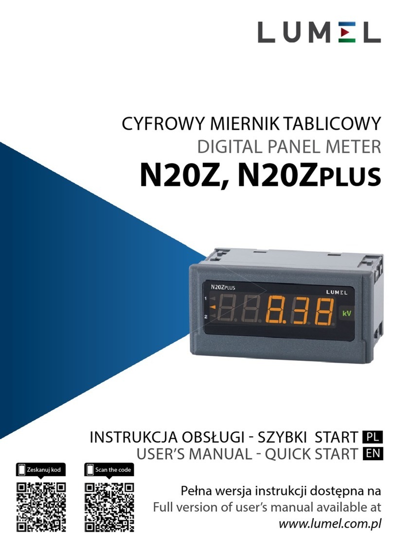
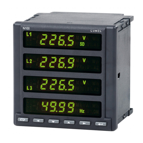
Fig.1. View of the NA6 meter.
$
NA6 meters can have in option: a continuous analogue output, a relay output,
open collector (OC) type outputs and an RS-485 digital output.
They are programmed by means of the keyboard and through RS-485.
NA6 meters realise following functions:
–measurement of the input quantity and displaying it on the display and the
bargraphs,
–recounting of the input signal into indication on the base of the individual
linear characteristic,
–arithmetical functions on channels: addition, subtraction, multiplication,
division, raising to a power, extraction of roots,
–programming of colours and bargraph resolutions,
–signalling of alarm value setting exceedings,
–recording of the measured signal in programmed time segments,
–storage of maximal and minimal values,
–programming of the measurement averaging time,
–programming of the indication resolution,
–deadlock of the parameter introduction by means of a password,
–conversion of the measured quantity into a voltage or current output signal,
–service of the RS-485 interface in MODBUS protocol, both in ASCII
and RTU mode.
2. SET OF THE NA6 METER
We deliver in the set:
- NA6 meter 1 pc.
- users guide 1 pc.
- guarantee card 1 pc.
- plug with screw terminals 1 or 2 pcs (depending on execution)
- holders to fix the meter in the panel 2 pcs
- set of stickers with units 1 pc.
When unpacking the meter, please check whether the type and execution code on
the data plate correspond to the order.
%
!
?
!
3. BASIC REQUIREMENTS, SAFETY INFORMATION
Symbols located in this service manual mean:
WARNING!
Warning of potential, hazardous situations. Especially important. One must
acquaint with this before connecting the NA6 meter. The non-observance
of notices marked by these symbols can occasion severe injuries of the
personnel and the damage of the instrument.
CAUTION!
Designates a general useful note. If you observe it, handling of the meter
is made easier. One must take note of this when the instrument is
working inconsistently to the expectations.
Possible consequences if disregarded !
In the security scope the meter meets the requirements of the EEC
Low-Voltage directive (EN 61010 -1 issued by CENELEC).
Remar s concerning the operator safety:
1. General
lThe NA6 meter is destined to be mounted on a panel.
lNon-authorized removal of the required housing, inappropriate use, incorrect
installation or operation creates the risk of injury to personnel or damage to
equipment. For more detailed information please see the users guide.
lAll operations concerning transport, installation, and commissioning as well as
maintenance must be carried out by qualified, skilled personnel and national
regulations for the prevention of accidents must be observed.
lAccording to this basic safety information, qualified, skilled personnel are
persons who are familiar with the installation, assembly, commissioning, and
operation of the product and who have qualifications necessary for their
occupation.
2. Transport, storage
Please observe the notes on transport, storage and appropriate handling. Observe
the climatic conditions given in Technical Data.
3. Installation
lThe NA6 meter must be installed according to the regulation and instructions
given in this users guide.
&
lEnsure proper handling and avoid mechanical stress.
lDo not bend any components and do not change any insulation distances.
lDo not touch any electronic components and contacts.
lInstruments may contain electrostatically sensitive components, which can easily
be damaged by inappropriate handling.
lDo not damage or destroy any electrical components since this might
endanger your health!
4. Electrical connection
lBefore switching the meter on, one must check the correctness of connection
to the network.
lIn case of the protection terminal connection with a separate lead one must
remember to connect it before the connection of the instrument to the mains.
lWhen working on live instruments, the applicable national regulations for the
prevention of accidents must be observed.
lThe electrical installation must be carried out according to the appropriate
regulations (cable cross-sections, fuses, PE connection). Additional
information can be obtained from the users guide.

lThe documentation contains information about installation in compliance with
EMC (shielding, grounding, filters and cables). These notes must be observed
for all CE-marked products.
lThe manufacturer of the measuring system or installed devices is responsible
for the compliance with the required limit values demanded by the EMC
legislation.
5. Operation
lMeasuring systems including NA6 meters must be equipped with protection
devices according to the corresponding standard and regulations for
prevention of accidents.
lAfter the instrument has been disconnected from the supply voltage, live
components and power connections must not be touched immediately because
capacitors can be charged.
lThe housing and the door must be closed during operation.
6. Maintenance and servicing
Please observe the manufacturers documentation.
Read all product-specific safety and application notes in this users guide manual
'
Fig. 2. eter overall dimension
48
144
77
max 92
8
lBefore taking the meter housing out, one must turn the supply off.
lThe removal of the instrument housing during the guarantee contract period
may cause its cancellation.
4. INSTALLATION
4.1. Fitting
Prepare a (44+0.5 x 137.5+0.5) mm hole in the panel. The thickness of the material
from which the panel is made should be in the range 1...45 mm.
The meter has screw terminal strips which enable the connection of 2.5 mm2 cross-
section external conductors.
Meter dimensions are shown on the fig. 2.

4.2. Ext rnal conn ction diagrams
The description of terminal strips are shown on the fig. 3a.
Connections of input signals are shown on the fig 3b and output signals on fig. 3c
and 3d.
The meter has programmable inputs. Maximal measuring ranges are given on
figures.
6
1
2
5
3
4
12
7
8
11
9
10
15
14
13
21
17
20
18
19
27
22
23
26
24
25
30
29
28
1632
31
A1
A3
A5
A7
RS-485
A
B
GND
A2
A4
A6
A8
A1
A3
A5
A7
GND
E
Resistance thermometer
Power supply
Analogue
output
8 OC outputs
4 rela outputs
Supply of object
transducers
24Vd.c.
GND
GND
±5A
±5A
±40 mA
±40 mA
±600 V
±600 V
Thermocouple or 300 mV
voltage from shunt
±
Thermocouple or 300 mV
voltage from shunt
±
Channel 2
Channel 1
a/ Description of the terminal strip