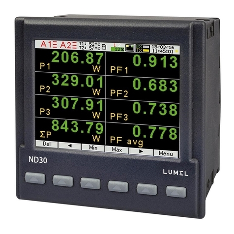
Lumel ND25 User manual

ND.25
POWER NETWORK METER
USER’S MANUAL
FOR INTERFACE


Section Contents
1. Introduction
2. Communication Parameter selection screen
2.1 Address Setting
2.2 RS 485 Baud rate
2.3 RS 485 Parity
2.4 Quit Communication Parameters
3. RS 485 ( ModBus ) Output
3.1 Accessing 3X and 4X registers for Reading Measured values
3.2 Accessing 4X register for Reading & Writing Settings
3.3 User Assignable Modbus Registers
4. Datalogging
4.1 Event Based Datalogging
4.2 Time Based Datalogging
4.3 Load Profile Datalogging
5. Connection for RS 485
1

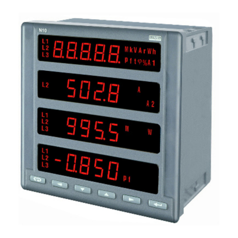
The Multifunction Energy Meter is a panel mounted 96 x 96mm DIN Quadratic Digital Panel Meter, which
measures important electrical parameters in 3 ph 4 wire / 3 wire / 1ph Network and replaces the multiple
analog panel meters. It measures electrical parameters like AC voltage, Current, Frequency, Power, Energy
(Active / Reactive / Apparent), phase angle, power factor,individual harmonics & many more. The instrument
integrates accurate measurement technology (All Voltages & current measurements are True RMS upto 31st
Harmonic) with LCD display with backlit.
It can be configured & Programmed at site for the following :PT Primary, PT Secondary, CT Primary, CT
Secondary , 3 Phase 3W, 3 Phase 4W, 1 Phase 2W system.
The front panel has three push buttons using which the user can scroll through different screens & configure
the product. The front panel also has Impulse red led, flashing at rate proportional to measured power.
Up Key
Enter Key
Down Key
Energy/Counter Screen
Measurement Screen
Load Graphics
Phase Sequence
Indication
Impulse LED
1. Introduction
Operation via standard RS485 is also possible. Through this optional interface all the above mentioned
parameters can be configured and programmed. For modbus service, it is essential that device address, baud rate
and parity should be configured properly.
This document specifies only the interface between a Master device and Meter for electrical variable through
MODBUS over RS485.
2

Press “ ” to enter into edit mode, prompt for first digit. (Flashing digit
indicates cursor position).
Press the “ ” and “ ” keys to scroll the value of the first digit. Press the
“ ” key to advance to next digit.
Similarly, enter second and third digits of address. After entering third digit,
pressing “ ” key confirms the selection and shows “Address Setting”
screen (see Section 3.2.2.1).
2.1 Address Setting
This screen applies to the RS 485 output only. This screen allows the user
to set RS 485 address for the meter.
The allowable range of addresses is 1 to 247.
Press “ ” key to advance to “RS 485 Baud Rate” screen (see Section
2.2) or press the “ ” key to advance to the “Quit Communication
Parameters” screen (see Section 2.4).
2. Communication Parameter Selection Screen
2.2 RS 485 Baud Rate
k
This screen allows the user to set Baud Rate of RS 485 port. The values
displayed on screen are in kbaud.
Pressing “ ” key accepts the present value and advance to the “RS 485
Parity Selection” screen (see Section 2.3) and pressing the “ ” key
accepts the present value and advance to the “Address Setting”
screen(see Section 2.1).
Pressing the “ ” key advances to the “Baud Rate Edit” mode and “ ” &
“ ” keys scrolls the value through 4.8, 9.6, 19.2, 38.4 and 57.6 kbaud.
Pressing the “ ” key sets the value and shows the “RS 485 Baud Rate” screen (see Section 2.2).
While using USB port communication the Configuration must be :
Device address: 001 Baud rate : 57600
Parity : None Stop bit: 1
3

2.3 RS 485 Parity
This screen allows the user to set Parity & number of stop bits of RS 485 port.
Pressing “ ” key accepts the present value and advances to “Quit
Communication Parameters” screen (see section 2.4).
Similarly, pressing “ ” key accepts the present value and advances to
“RS 485 Baud Rate” screen (see section 2.2).
Pressing the “ ” key advances to the “Parity & Stop bit Edit” mode &
keys “ ” and “ ” scrolls the value through:
no 1 : no parity with one stop bit no 2 : no parity with two stop bit
E : even parity with one stop bit odd : odd parity with one stop bit
Pressing “ ” key sets the value and advances to “RS 485 Parity Selection” screen (see Section 2.3).
2.4 Quit Communication Parameters
This screen allows user to exit from system “Communication
Parameter Selection” setup.
Pressing the “ ” key advances to “Communication Parameter Selection”
screen (see Section 2.1).
Similarly, pressing the “ ” key advances to “RS 485 Parity” screen (see
Section 2.3).
Pressing the “ ” key advances to “Communication Parameter Selection ”
screen (see Section 2).
3. RS 485 ( ModBus ) Output :
THE MULTIFUNCTION INSTRUMENT supports MODBUS (RS485) RTU protocol (2-wire ) .
Connection should be made using twisted pair shielded cable. All "A" and "B" connections are daisy chained
together. The screens should also be connected to the “Gnd” terminal. To avoid the possibility of loop currents,
an Earth connection should be made at one point on the network. Loop (ring) topology does not require any
termination load. Line topology may or may not require terminating loads depending on the type and length of
cable used. The impedance of the termination load should match the impedance of the cable and be at both
ends of the line. The cable should be terminated at each end with a 120 ohm (1/4 Watt min.) resistor.
RS 485 network supports maximum length of 1.2km. Including the Master, a maximum of 32 instruments can
be connected in RS485 network. The permissible address range for The Meter is between 1 and 247
for 32 instruments. Broadcast Mode (address 0) is not allowed.
The maximum latency time of a Meter is 300 ms i.e. this is the amount of time that can pass before the first
response character is output.
4

After sending any query through software (of the Master), it must allow 300ms of time to elapse before assuming
that the Meter is not going to respond. If slave does not respond within 300 ms, Master can ignore the previous
query and can issue fresh query to the slave.
16 Presets Multiple Registers Set the content of read / write locations ( 4X )
04 Read input Registers Read content of read only location ( 3X )
Read Holding Registers Read content of read /write location ( 4X )
03
Communication Baud Rate is user selectable from the front panel between 4800,9600,19200,38400,57600 bps.
Function code :
8-bit binary, hexadecimal 0-9, A-F
2 hexadecimal characters contained in each 8-bit field of the message
4 bytes (32 bits) per parameter.
Floating point format ( to IEEE 754)
Most significant byte first (Alternative least significant byte first)
Format of Data Bytes
2 byte Cyclical Redundancy Check (CRC)
Error Checking Bytes
1 start bit,
8 data bits, least significant bit sent first
1 bit for even/odd parity
1 stop bit if parity is used; 1 or 2 bits if no parity
Byte format
Each byte in RTU mode has following format:
01 Illegal function The function code is not supported by Meter
02 Illegal Data Address Attempt to access an invalid address or an
attempt to read or write part of a floating point value
03 Illegal DataValue Attempt to set a floating point variable to an invalid value
Exception Cases : An exception code will be generated when Meter receives ModBus query with valid parity
& error check but which contains some other error ( e.g. Attempt to set floating point variable to an invalid value)
The response generated will be “Function code” ORed with HEX (80H ). The exception codes are listed below
3.1 Accessing 3X and 4X register for reading measured values:
Two consecutive 16 bit registers represent one parameter. Refer TABLE 1 for the addresses of 3X and 4X
registers used for parameters measured by the instrument. Each parameter is held in the 3X as well as 4X
registers. Modbus Code 04 and 03 are used to access all parameters in 3X and 4X registers respectively.
Example :
To read parameter,
Voltage2 from 3X: Start address = 00 02 Number of registers = 02
Watt2 from 4X: Start address = 00 0E Number of registers = 02
5

Note : Number of registers = Number of parameters x 2
Each Query for reading the data must be restricted to 40 parameters or less. Exceeding the 40 parameter
limit will cause a ModBus exception code to be returned.
Device
Address
Function
Code
Start Address
High
Start Address
Low
Number of
Registers Hi
Number of
Registers Lo
CRC
Low
CRC
High
01 (Hex) 04 (Hex) 00 (Hex) 02(Hex) 00 (Hex) 02(Hex) 30 (Hex) 0A (Hex)
Query for 3X read:
3X Response: Voltage 2 (219.254V)
Device
Address
Function
Code
Byte
Count
Data Register1
High Byte
CRC
High
01 (Hex) 04 (Hex) 04 (Hex) 43 (Hex) 5B (Hex) 41 (Hex) 21 (Hex) 6F (Hex)
Data Register1
Low Byte
Data Register2
High Byte
Data Register2
Low Byte
9B (Hex)
CRC
Low
Byte Count : Total number of data bytes received.
Query for 4X read:
Device
Address
Function
Code
Start Address
High
Start Address
Low
Number of
Registers Hi
Number of
Registers Lo
CRC
Low
CRC
High
01 (Hex) 03 (Hex) 00 (Hex) 0E(Hex) 00 (Hex) 02(Hex) E0 (Hex) C9 (Hex)
4X Response: Watt2 (2000 W)
Device
Address
Function
Code
Byte
Count
Data Register1
High Byte
CRC
High
01 (Hex) 03 (Hex) 04 (Hex) 44 (Hex) FA (Hex) 00 (Hex) 00 (Hex) CE (Hex)
Data Register1
Low Byte
Data Register2
High Byte
Data Register2
Low Byte
F2 (Hex)
CRC
Low
Start Address High : Most significant 8 bits of starting address of the parameter requested.
Start Address low : Least significant 8 bits of starting address of the parameter requested.
Number of register Hi : Most significant 8 bits of Number of registers requested.
Number of register Lo : Least significant 8 bits of Number of registers requested.
Data register 1 High Byte : Most significant 8 bits of Data register 1 of the parameter requested.
Data register 1 Low Byte : Least significant 8 bits of Data register 1 of the parameter requested.
Data register 2 High Byte : Most significant 8 bits of Data register 2 of the parameter requested.
Data register 2 Low Byte : Least significant 8 bits of Data register 2 of the parameter requested.
(Note : Two consecutive 16 bit register represent one parameter.)
Byte count : No.of Bytes Demanded by user in querry.
6

TABLE 1 : 3 X and 4 X register addresses for measured parameters
Address
(3X)
Address
(4X)
Parameter
Number Parameter
Start Address Hex 3X Start Address Hex 4X
High Byte Low Byte High Byte Low Byte
30001
30003
30005
30007
30009
30011
30013
30015
30017
30019
30021
30023
30025
30027
30029
30031
30033
30035
30037
30039
30041
30043
30045
30047
30049
30051
30053
30055
30057
30059
40001
40003
40005
40007
40009
40011
40013
40015
40017
40019
40021
40023
40025
40027
40029
40031
40033
40035
40037
40039
40041
40043
40045
40047
40049
40051
40053
40055
40057
40059
1
2
3
4
5
6
7
8
9
10
11
12
13
14
15
16
17
18
19
20
21
22
23
24
25
26
27
28
29
30
V1
V2
V3
I1
I2
I3
W1
W2
W3
VA1
VA2
VA3
VAR1
VAR2
VAR3
PF1
PF2
PF3
Angle1
Angle2
Angle3
Volt Avg
Volt Sum
Current Avg
Current Sum
Watt Avg
Watt Sum
VA Avg
VA Sum
VAr Avg
00
00
00
00
00
00
00
00
00
00
00
00
00
00
00
00
00
00
00
00
00
00
00
00
00
00
00
00
00
00
00
02
04
06
08
0A
0C
0E
10
12
14
16
18
1A
1C
1E
20
22
24
26
28
2A
2C
2E
30
32
34
36
38
3A
00
00
00
00
00
00
00
00
00
00
00
00
00
00
00
00
00
00
00
00
00
00
00
00
00
00
00
00
00
00
00
02
04
06
08
0A
0C
0E
10
12
14
16
18
1A
1C
1E
20
22
24
26
28
2A
2C
2E
30
32
34
36
38
3A
7

TABLE 1 : Continued...
Address
(3X)
Address
(4X)
Parameter
Number Parameter
Start Address Hex 3X Start Address Hex 4X
High Byte Low Byte High Byte Low Byte
30061
30063
30065
30067
30069
30071
30073
30075
30077
30079
30081
30085
30087
30089
30091
30093
30095
30097
30099
30101
30103
30105
30107
30109
30111
30113
30115
30117
30119
30121
40061
40063
40065
40067
40069
40071
40073
40075
40077
40079
40081
40085
40087
40089
40091
40093
40095
40097
40099
40101
40103
40105
40107
40109
40111
40113
40115
40117
40119
40121
31
32
33
34
35
36
37
38
39
40
41
43
44
45
46
47
48
49
50
51
52
53
54
55
56
57
58
59
60
61
VAr Sum
PF Avg
PF Sum
Phase Angle Avg
Phase Angle Sum
Freq
Wh import
Wh export
VArh Capacitive
VArh Inductive
VAh
kW imp demand
max kW imp demand
kW exp demand
max kW exp demand
kVAr Cap. demand
max kVAr Cap. demand
kVAr Ind. demand
max kVAr Ind. demand
KVA demand
max KVA demand
current demand
max current demand
Wh import Overflow count
Wh Import
Wh export Overflow count
Wh export
VArh Cap. Overflow count
VArh Capacitive
VArh Ind. Overflow count
00
00
00
00
00
00
00
00
00
00
00
00
00
00
00
00
00
00
00
00
00
00
00
00
00
00
00
00
00
00
3C
3E
40
42
44
46
48
4A
4C
4E
50
54
56
58
5A
5C
5E
60
62
64
66
68
6A
6C
6E
70
72
74
76
78
00
00
00
00
00
00
00
00
00
00
00
00
00
00
00
00
00
00
00
00
00
00
00
00
00
00
00
00
00
00
3C
3E
40
42
44
46
48
4A
4C
4E
50
54
56
58
5A
5C
5E
60
62
64
66
68
6A
6C
6E
70
72
74
76
78
8

TABLE 1 : Continued...
Address
(3X)
Address
(4X)
Para.
No. Parameter
Start Address Hex 3X Start Address Hex 4X
High Byte Low Byte High Byte Low Byte
30123
30125
30127
30133
30135
30137
30139
30141
30143
30145
30147
30149
30151
30153
30157
30159
30161
30163
30165
30169
30171
30173
30175
30177
30179
30181
30183
30185
30187
62
63
64
67
68
69
70
71
72
73
74
75
76
77
79
80
81
82
83
85
86
87
88
89
90
91
92
93
94
VARh Inductive
VAh Overflow count
VAh
System Voltage Max
System Voltage Min
RPM
Impulse Rate
System Current Max
System Current Min
Wh imp. depending on update rate*
Wh exp. depending on update rate*
VArh cap. depending on update rate*
VArh ind. depending on update rate*
VAh depending on update rate*
VAh OFC depending on update rate*
Old Wh imp OFC
Old Wh imp
Old Wh exp OFC
Old Wh exp
Old VArh Cap. OFC
Old VArh Cap.
Old VArh Ind.OFC
Old VArh Ind.
Old VAh OFC
Old VAh
00
00
00
00
00
00
00
00
00
00
00
00
00
00
00
00
00
00
00
00
00
00
00
00
00
00
00
00
00
7A
7C
7E
84
86
88
8A
8C
8E
90
92
94
96
98
9C
9E
A0
A2
A4
A8
AA
AC
AE
B0
B2
B4
B6
B8
BA
40123
40125
40127
40133
40135
40137
40139
40141
40143
40145
40147
40149
40151
40153
40157
40159
40161
40163
40165
40169
40171
40173
40175
40177
40179
40181
40183
40185
40187
00
00
00
00
00
00
00
00
00
00
00
00
00
00
00
00
00
00
00
00
00
00
00
00
00
00
00
00
00
Wh imp OFC depending on update rate*
Wh exp OFC depending on update rate*
VArh Cap. OFC depending on update rate *
VArh Ind. OFC depending on update rate *
7A
7C
7E
84
86
88
8A
8C
8E
90
92
94
96
98
9C
9E
A0
A2
A4
A8
AA
AC
AE
B0
B2
B4
B6
B8
BA
9

TABLE 1 : Continued...
30201
30203
30205
30207
30209
30211
30213
30215
30217
30219
30221
30225
30227
30229
30231
30251
30255
30263
30267
30269
30271
30273
30275
30277
30279
30281
101
102
103
104
105
106
107
108
109
110
111
113
114
115
116
126
128
132
134
135
136
137
138
139
140
141
V12
V23
V31
VTHD-R
VTHD-Y
VTHD-B
ITHD-R
ITHD-Y
ITHD-B
System V-THD
System I-THD
Neutral Current
Run hour
On Hour
No. of interrupts
Old run hour
Old on hour
Old No. of int.
Relay 1 status
Relay 2 status
old max imp W demand
old max exp W demand
old max Cap. VArh demand
old max Ind. VArh demand
old max VA demand
old max A demand
00
00
00
00
00
00
00
00
00
00
00
00
00
00
00
00
00
01
01
01
01
01
01
01
01
01
C8
CA
CC
CE
D0
D2
D4
D6
D8
DA
DC
E0
E2
E4
E6
FA
FE
06
0A
0C
0E
10
12
14
16
18
40201
40203
40205
40207
40209
40211
40213
40215
40217
40219
40221
40225
40227
40229
40231
40251
40255
40263
40267
40269
40271
40273
40275
40277
40279
40281
00
00
00
00
00
00
00
00
00
00
00
00
00
00
00
00
00
01
01
01
01
01
01
01
01
01
Address
(3X)
Address
(4X)
Parameter
Number Parameter
Start Address Hex 3X Start Address Hex 4X
High Byte Low Byte High Byte Low Byte
C8
CA
CC
CE
D0
D2
D4
D6
D8
DA
DC
E0
E2
E4
E6
FA
FE
06
0A
0C
0E
10
12
14
16
18
10

TABLE 1 : Continued...
30293
30295
30297
30299
30301
30303
30305
30307
30333
30337
30345
30347
30349
30351
30353
30355
30357
30359
30361
30363
30365
30367
30401
30403
30405
147
148
149
150
151
152
153
154
167
169
173
174
175
176
177
178
179
180
181
182
183
184
201
202
203
RTC Minute
RTC Hour
RTC Day
RTC Date
RTC Month
RTC Year
RTC Complete date
RTC Complete time
Phase indicate
Temperature
Power Down RTC Minute
Power Down RTC Hour
Power Down RTC Day
Power Down RTC Date
Power Down RTC Month
Power Down RTC Year
Timer 1 On delay
Timer 2 On delay
Timer 1 Off delay
Timer 2 Off delay
Timer 1 No. of Cycles
Timer 2 No. of Cycles
VR Harmonic-1
IR Harmonic-1
VR Harmonic-2
01
01
01
01
01
01
01
01
01
01
01
01
01
01
01
01
01
01
01
01
01
01
01
01
01
24
26
28
2A
2C
2E
30
32
4C
50
58
5A
5C
5E
60
62
64
66
68
6A
6C
6E
90
92
94
40293
40295
40297
40299
40301
40303
40305
40307
40333
40337
40345
40347
40349
40351
40353
40355
40357
40359
40361
40363
40365
40367
40401
40403
40405
01
01
01
01
01
01
01
01
01
01
01
01
01
01
01
01
01
01
01
01
01
01
01
01
01
Address
(3X)
Address
(4X)
Parameter
Number Parameter
Start Address Hex 3X Start Address Hex 4X
High Byte Low Byte High Byte Low Byte
24
26
28
2A
2C
2E
30
32
4C
50
58
5A
5C
5E
60
62
64
66
68
6A
6C
6E
90
92
94
11

TABLE 1 : Continued...
Address
(3X)
Address
(4X)
Parameter
Number Parameter
Start Address Hex 3X Start Address Hex 4X
High Byte Low Byte High Byte Low Byte
30407
30409
30411
30413
30415
30417
30419
30421
30423
30425
30427
30429
30431
30433
30435
30437
30439
30441
30443
30445
30447
30449
30451
30453
30455
30457
30459
30461
30463
30465
204
205
206
207
208
209
210
211
212
213
214
215
216
217
218
219
220
221
222
223
224
225
226
227
228
229
230
231
232
233
IR Harmonic-2
VR Harmonic-3
IR Harmonic-3
VR Harmonic-4
IR Harmonic-4
VR Harmonic-5
IR Harmonic-5
VR Harmonic-6
IR Harmonic-6
VR Harmonic-7
IR Harmonic-7
VR Harmonic-8
IR Harmonic-8
VR Harmonic-9
IR Harmonic-9
VR Harmonic-10
IR Harmonic-10
VR Harmonic-11
IR Harmonic-11
VR Harmonic-12
IR Harmonic-12
VR Harmonic-13
IR Harmonic-13
VR Harmonic-14
IR Harmonic-14
VR Harmonic-15
IR Harmonic-15
VR Harmonic-16
IR Harmonic-16
VR Harmonic-17
01
01
01
01
01
01
01
01
01
01
01
01
01
01
01
01
01
01
01
01
01
01
01
01
01
01
01
01
01
01
40407
40409
40411
40413
40415
40417
40419
40421
40423
40425
40427
40429
40431
40433
40435
40437
40439
40441
40443
40445
40447
40449
40451
40453
40455
40457
40459
40461
40463
40465
01
01
01
01
01
01
01
01
01
01
01
01
01
01
01
01
01
01
01
01
01
01
01
01
01
01
01
01
01
01
96
98
9A
9C
9E
A0
A2
A4
A6
A8
AA
AC
AE
B0
B2
B4
B6
B8
BA
BC
BE
C0
C2
C4
C6
C8
CA
CC
CE
D0
96
98
9A
9C
9E
A0
A2
A4
A6
A8
AA
AC
AE
B0
B2
B4
B6
B8
BA
BC
BE
C0
C2
C4
C6
C8
CA
CC
CE
D0
12

TABLE 1 : Continued...
Address
(3X)
Address
(4X)
Parameter
Number Parameter
Start Address Hex 3X Start Address Hex 4X
High Byte Low Byte High Byte Low Byte
30467
30469
30471
30473
30475
30477
30479
30481
30483
30485
30487
30489
30491
30493
30495
30497
30499
30501
30503
30505
30507
30509
30511
30513
30515
30517
30519
30521
30523
30525
234
235
236
237
238
239
240
241
242
243
244
245
246
247
248
249
250
251
252
253
254
255
256
257
258
259
260
261
262
263
IR Harmonic-17
VR Harmonic-18
IR Harmonic-18
VR Harmonic-19
IR Harmonic-19
VR Harmonic-20
IR Harmonic-20
VR Harmonic-21
IR Harmonic-21
VR Harmonic-22
IR Harmonic-22
VR Harmonic-23
IR Harmonic-23
VR Harmonic-24
IR Harmonic-24
VR Harmonic-25
IR Harmonic-25
VR Harmonic-26
IR Harmonic-26
VR Harmonic-27
IR Harmonic-27
VR Harmonic-28
IR Harmonic-28
VR Harmonic-29
IR Harmonic-29
VR Harmonic-30
IR Harmonic-30
VR Harmonic-31
IR Harmonic-31
VR Harmonic-32
01
01
01
01
01
01
01
01
01
01
01
01
01
01
01
01
01
01
01
01
01
01
01
02
02
02
02
02
02
02
40467
40469
40471
40473
40475
40477
40479
40481
40483
40485
40487
40489
40491
40493
40495
40497
40499
40501
40503
40505
40507
40509
40511
40513
40515
40517
40519
40521
40523
40525
01
01
01
01
01
01
01
01
01
01
01
01
01
01
01
01
01
01
01
01
01
01
01
02
02
02
02
02
02
02
D2
D4
D6
D8
DA
DC
DE
E0
E2
E4
E6
E8
EA
EC
EE
F0
F2
F4
F6
F8
FA
FC
FE
00
02
04
06
08
0A
0C
D2
D4
D6
D8
DA
DC
DE
E0
E2
E4
E6
E8
EA
EC
EE
F0
F2
F4
F6
F8
FA
FC
FE
00
02
04
06
08
0A
0C
13

TABLE 1 : Continued...
Address
(3X)
Address
(4X)
Parameter
Number Parameter
Start Address Hex 3X Start Address Hex 4X
High Byte Low Byte High Byte Low Byte
30527
30529
30531
30533
30535
30537
30539
30541
30543
30545
30547
30549
30551
30553
30555
30557
30559
30561
30563
30565
30567
30569
30571
30573
30575
30577
30579
30581
30583
30585
264
265
266
267
268
269
270
271
272
273
274
275
276
277
278
279
280
281
282
283
284
285
286
287
288
289
290
291
292
293
IR Harmonic-32
VY Harmonic-1
IY Harmonic-1
VY Harmonic-2
IY Harmonic-2
VY Harmonic-3
IY Harmonic-3
VY Harmonic-4
IY Harmonic-4
VY Harmonic-5
IY Harmonic-5
VY Harmonic-6
IY Harmonic-6
VY Harmonic-7
IY Harmonic-7
VY Harmonic-8
IY Harmonic-8
VY Harmonic-9
IY Harmonic-9
VY Harmonic-10
IY Harmonic-10
VY Harmonic-11
IY Harmonic-11
VY Harmonic-12
IY Harmonic-12
VY Harmonic-13
IY Harmonic-13
VY Harmonic-14
IY Harmonic-14
VY Harmonic-15
02
02
02
02
02
02
02
02
02
02
02
02
02
02
02
02
02
02
02
02
02
02
02
02
02
02
02
02
02
02
0E
10
12
14
16
18
1A
1C
1E
20
22
24
26
28
2A
2C
2E
30
32
34
36
38
3A
3C
3E
40
42
44
46
48
40527
40529
40531
40533
40535
40537
40539
40541
40543
40545
40547
40549
40551
40553
40555
40557
40559
40561
40563
40565
40567
40569
40571
40573
40575
40577
40579
40581
40583
40585
02
02
02
02
02
02
02
02
02
02
02
02
02
02
02
02
02
02
02
02
02
02
02
02
02
02
02
02
02
02
0E
10
12
14
16
18
1A
1C
1E
20
22
24
26
28
2A
2C
2E
30
32
34
36
38
3A
3C
3E
40
42
44
46
48
14

TABLE 1 : Continued...
Address
(3X)
Address
(4X)
Parameter
Number Parameter
Start Address Hex 3X Start Address Hex 4X
High Byte Low Byte High Byte Low Byte
30587
30589
30591
30593
30595
30597
30599
30601
30603
30605
30607
30609
30611
30613
30615
30617
30619
30621
30623
30625
30627
30629
30631
30633
30635
30637
30639
30641
30643
30645
294
295
296
297
298
299
300
301
302
303
304
305
306
307
308
309
310
311
312
313
314
315
316
317
318
319
320
321
322
323
IY Harmonic-15
VY Harmonic-16
IY Harmonic-16
VY Harmonic-17
IY Harmonic-17
VY Harmonic-18
IY Harmonic-18
VY Harmonic-19
IY Harmonic-19
VY Harmonic-20
IY Harmonic-20
VY Harmonic-21
IY Harmonic-21
VY Harmonic-22
IY Harmonic-22
VY Harmonic-23
IY Harmonic-23
VY Harmonic-24
IY Harmonic-24
VY Harmonic-25
IY Harmonic-25
VY Harmonic-26
IY Harmonic-26
VY Harmonic-27
IY Harmonic-27
VY Harmonic-28
IY Harmonic-28
VY Harmonic-29
IY Harmonic-29
VY Harmonic-30
02
02
02
02
02
02
02
02
02
02
02
02
02
02
02
02
02
02
02
02
02
02
02
02
02
02
02
02
02
02
4A
4C
4E
50
52
54
56
58
5A
5C
5E
60
62
64
66
68
6A
6C
6E
70
72
74
76
78
7A
7C
7E
80
82
84
40587
40589
40591
40593
40595
40597
40599
40601
40603
40605
40607
40609
40611
40613
40615
40617
40619
40621
40623
40625
40627
40629
40631
40633
40635
40637
40639
40641
40643
40645
02
02
02
02
02
02
02
02
02
02
02
02
02
02
02
02
02
02
02
02
02
02
02
02
02
02
02
02
02
02
4A
4C
4E
50
52
54
56
58
5A
5C
5E
60
62
64
66
68
6A
6C
6E
70
72
74
76
78
7A
7C
7E
80
82
84
15

TABLE 1 : Continued...
Address
(3X)
Address
(4X)
Parameter
Number Parameter
Start Address Hex 3X Start Address Hex 4X
High Byte Low Byte High Byte Low Byte
30647
30649
30651
30653
30655
30657
30659
30661
30663
30665
30667
30669
30671
30673
30675
30677
30679
30681
30683
30685
30687
30689
30691
30693
30695
30697
30699
30701
30703
30705
324
325
326
327
328
329
330
331
332
333
334
335
336
337
338
339
340
341
342
343
344
345
346
347
348
349
350
351
352
353
IY Harmonic-30
VY Harmonic-31
IY Harmonic-31
VY Harmonic-32
IY Harmonic-32
VB Harmonic-1
IB Harmonic-1
VB Harmonic-2
IB Harmonic-2
VB Harmonic-3
IB Harmonic-3
VB Harmonic-4
IB Harmonic-4
VB Harmonic-5
IB Harmonic-5
VB Harmonic-6
IB Harmonic-6
VB Harmonic-7
IB Harmonic-7
VB Harmonic-8
IB Harmonic-8
VB Harmonic-9
IB Harmonic-9
VB Harmonic-10
IB Harmonic-10
VB Harmonic-11
IB Harmonic-11
VB Harmonic-12
IB Harmonic-12
VB Harmonic-13
02
02
02
02
02
02
02
02
02
02
02
02
02
02
02
02
02
02
02
02
02
02
02
02
02
02
02
02
02
02
86
88
8A
8C
8E
90
92
94
96
98
9A
9C
9E
A0
A2
A4
A6
A8
AA
AC
AE
B0
B2
B4
B6
B8
BA
BC
BE
C0
40647
40649
40651
40653
40655
40657
40659
40661
40663
40665
40667
40669
40671
40673
40675
40677
40679
40681
40683
40685
40687
40689
40691
40693
40695
40697
40699
40701
40703
40705
02
02
02
02
02
02
02
02
02
02
02
02
02
02
02
02
02
02
02
02
02
02
02
02
02
02
02
02
02
02
86
88
8A
8C
8E
90
92
94
96
98
9A
9C
9E
A0
A2
A4
A6
A8
AA
AC
AE
B0
B2
B4
B6
B8
BA
BC
BE
C0
16

TABLE 1 : Continued...
Address
(3X)
Address
(4X)
Parameter
Number Parameter
Start Address Hex 3X Start Address Hex 4X
High Byte Low Byte High Byte Low Byte
30707
30709
30711
30713
30715
30717
30719
30721
30723
30725
30727
30729
30731
30733
30735
30737
30739
30741
30743
30745
30747
30749
30751
30753
30755
30757
30759
30761
30763
30765
354
355
356
357
358
359
360
361
362
363
364
365
366
367
368
369
370
371
372
373
374
375
376
377
378
379
380
381
382
383
IB Harmonic-13
VB Harmonic-14
IB Harmonic-14
VB Harmonic-15
IB Harmonic-15
VB Harmonic-16
IB Harmonic-16
VB Harmonic-17
IB Harmonic-17
VB Harmonic-18
IB Harmonic-18
VB Harmonic-19
IB Harmonic-19
VB Harmonic-20
IB Harmonic-20
VB Harmonic-21
IB Harmonic-21
VB Harmonic-22
IB Harmonic-22
VB Harmonic-23
IB Harmonic-23
VB Harmonic-24
IB Harmonic-24
VB Harmonic-25
IB Harmonic-25
VB Harmonic-26
IB Harmonic-26
VB Harmonic-27
IB Harmonic-27
VB Harmonic-28
02
02
02
02
02
02
02
02
02
02
02
02
02
02
02
02
02
02
02
02
02
02
02
02
02
02
02
02
02
02
C2
C4
C6
C8
CA
CC
CE
D0
D2
D4
D6
D8
DA
DC
DE
E0
E2
E4
E6
E8
EA
EC
EE
F0
F2
F4
F6
F8
FA
FC
40707
40709
40711
40713
40715
40717
40719
40721
40723
40725
40727
40729
40731
40733
40735
40737
40739
40741
40743
40745
40747
40749
40751
40753
40755
40757
40759
40761
40763
40765
02
02
02
02
02
02
02
02
02
02
02
02
02
02
02
02
02
02
02
02
02
02
02
02
02
02
02
02
02
02
C2
C4
C6
C8
CA
CC
CE
D0
D2
D4
D6
D8
DA
DC
DE
E0
E2
E4
E6
E8
EA
EC
EE
F0
F2
F4
F6
F8
FA
FC
17

TABLE 1 : Continued...
Address
(3X)
Address
(4X)
Parameter
Number Parameter
Start Address Hex 3X Start Address Hex 4X
High Byte Low Byte High Byte Low Byte
30767
30769
30771
30773
30775
30777
30779
30781
30783
384
385
386
387
388
389
390
391
392
IB Harmonic-28
VB Harmonic-29
IB Harmonic-29
VB Harmonic-30
IB Harmonic-30
VB Harmonic-31
IB Harmonic-31
VB Harmonic-32
IB Harmonic-32
02
03
03
03
03
03
03
03
03
FE
00
02
04
06
08
0A
0C
0E
40767
40769
40771
40773
40775
40777
40779
40781
40783
02
03
03
03
03
03
03
03
03
FE
00
02
04
06
08
0A
0C
0E
Note : 1. Parameters 1,2,3 are L-N Voltage for 3P 4W & L-L Voltage for 3P 3W.
2. Relay Output 1/ 2 Status shows whether relay is Energized or De-energized.
1 :- Relay Energized 0:- Relay De-energized
TABLE 2 : 3X and 4X register addresses for 32-bit Integer Energy
30801
30803
30805
30807
30809
30813
30815
30817
30819
30821
30825
30827
30829
Active Energy Import
Active Energy Export
Reactive Energy Capacitive
Reactive Energy Inductive
Apparent Energy
Active Energy Import Overflow Count
Active Energy Export Overflow Count
Reactive Energy Cap. Overflow Count
Reactive Energy Ind. Overflow Count
Apparent Energy Overflow Count
Active Energy Import on time*
Active Energy Export on time*
Reactive Energy Cap. on time*
03
03
03
03
03
03
03
03
03
03
03
03
03
20
22
24
26
28
2C
2E
30
32
34
38
3A
3C
40801
40803
40805
40807
40809
40813
40815
40817
40819
40821
40825
40827
40829
03
03
03
03
03
03
03
03
03
03
03
03
03
Address
(3X)
Address
(4X) Parameter
Start Address Hex 3X Start Address Hex
Hi Byte Lo Byte Hi Byte Lo Byte
20
22
24
26
28
2C
2E
30
32
34
38
3A
3C
18
Table of contents
Other Lumel Measuring Instrument manuals