LYSON W2091 User manual

Instructions manual
Manual vertical uncapping machine
Przedsiębiorstwo Pszczelarskie Tomasz Łysoń
Spółka z o.o. Spółka Komandytowa
34-125 Sułkowice, ul. Racławicka 162, Polska
www.lyson.com.pl, email: [email protected]
tel.33/875-99-40, 33/870-64-02
Headquarters: Klecza Dolna 148, 34-124 Klecza Górna

The manual covers following devices (codes):
W2091, W2091S
Table of contents
1. General safety instructions
1.1. Intended use
1.2. Electrical safety
1.3. Operation safety
2. Instructions for use
2.1. General instructions – preparation for use
2.2. Operation instructions
3. Product description
3.1. Product design
3.2. Technical specifications
4. HC-01 controller
4.1. Setting up the controller
4.2. Controller’s features
4.3. Troubleshooting
5. Storage
6. Maintenance and cleaning
7. Waste disposal and environmental protection
8. Warranty
Product images are for illustrative purposes only and may sometimes differ from the actual appearance of the item.
However, this does not change their basic properties.

1. General safety instructions
Before first use read the manual carefully and
follow the instructions contained therein. The
manufacturer is not liable for damage caused by
equipment used inappropriately or by incorrect
handling.
1.1. Intended use
The uncapping machine is a device which al-
lows to mechanically prepare sealed off bee
combs for the honey extractions process.
1.2. Electrical safety
1. The electrical supply system must be fitted
with a residual-current circuit breaker with rated
tripping current not higher than 30mA.
Performance of the circuit breaker should be
checked periodically.
2. Periodically check the condition of the power
cord. Replace the power cord if damaged.
Replacing the power cord can only be
performed by the manufacturer or by qualified
personnel.
Do not use the device if the power cord is
damaged!
3. Make sure that the main switch (8) is in „0”
position before plugging the unit in.
4. Connect the device to a socket with voltage
specified on the rating plate of the product.
5. Carefully connect the plug into the mains
socket. Make sure your hands and the floor
surface in the room are dry!
6. Do not move the device during operation.
7. Protect the motor and the control unit against
moisture (also during storage).
8. Do not pull the power cord.
Keep the power cord away from heat sources
and sharp edges to ensure its good condition.
1.3 Operation safety
1. The device is not intended for use by
persons (including children) with limited
physical, sensory or mental abilities, or by
inexperienced users, unless under supervision or with
instructions given by an accountable party.
This device is not a toy, and shouldn’t be used as one.
Children should not to play with it.
2. In the event of damage to the device, to avoid any health
and safety risks, repairs should be carried out only by qualified
personnel.
3. Never carry out any maintenance or repairs during
operation or if the device is plugged in!
4. All covers must be firmly attached to the device during
operation.
5. In case of any unexpected event, use the safety switch
immediately. The device can be restarted after any possible
hazard has been eliminated.
6. For indoor use only. The device is not suitable for outdoor
use.
7. Do not use or store the device at the ambient temperature
below freezing. If the device has been moved from a cold room
to a room with a higher temperature, before switching on wait
until it reaches room temperature.
8. Be aware of hot and sharp blades of the device.
Do not remove covers during operation
HOT! Do not touch the blades during or immediately after
the work
WARNING – SHARP EDGES!

2. Instructions for use
2.1 General instructions –
preparation for use
1. Set the device up in a designated, clean,
dry and well lit room.
2. Keep a free space around the device for
better handling.
3. Provide easy access to the power source.
4. Closely follow the instructions of use.
NOTE!
Do not process frames WITH SPACERS
2.2 Operation instructions
1. The uncapping machine is a device which allows
to mechanically prepare sealed off bee combs for the
honey extractions process.
2. The device has to be cleaned before the first
use and after finishing work according to the
instructions in the "Cleaning and Maintenance"
section.
3. Before start:
–make sure that the device is firmly attached
to the table,
–loosen bolts (8) using an allen key 4,
–adjust the gap between the back blade
assembly (11) and the front blade assembly
(12),
–the gap between the blades (14) should be
appropriate for the specific type of frames,
–when the gap has been set, tighten the bolts
(8) using an allen key 4,
–turn on the controller (4) using main switch
(9),
–set the desired work temperature (10)
(instructions in section 4)
–turn on the temperature controller (10) and
wait until it reaches work temperature,
–uncap the frames holding the ends of the top
bar and pushing down through the device
–after uncapping, the frames rest on the
bottom rails of the uncapper,
–move the uncapped frames to the extractor
or hang them on the uncapping table’s rails.
Do not adjust any work parameters
while the machine is running.
3. Product description
The mechanical uncapping machine is designed to work
with 230V power supply
The blades of the machine are heated up by built in
heating elements with combined power of 1000W. The
adjustable knifes allow to optimise the operation of the
device and to properly uncap the frame surface. The
device is compatible with standard and Hoffman type
frames
3.1.Product design
1-power supply cord
2-temperature controller wire
3-knife heating system sockets
4-controller
5-fuse
6-front knife cover
7-table mounting guide
8-knife gap adjustment bolts
9-main switch 0-1
10-HC-01 temperature controller
11-back knife assembly
12-front knife assembly
13-back knife cover
14-uncapping knives
Fig.1
Fig.2

Fig.3
3.2.Technical specifications
Frame
-Made of 0H18N9 acid resistant stainless
steel
Heated knives :
-two oposing knives are heated by two built
in heating elements of 500W heat output
each. The temperature is controlled by the
HC-01 temperature controller with the range
of adjustment of 30-95°C.
Power Supply
-230V/AC
Available uncapping table
compatible with the machine are 750,
1000 i 1500mm.
Tables with a conical shaped bottom are
made of 0H18N9 acid-resistant stainless
steel, 0.8 mm thick. The table legs are
powder coated and height adjustable. The
tables are equipped with stainless sieves
covering the entire length of the bottom.
They are equipped with a 6/4 ”flap” design
drain valve.
Dimensions:
- uncapper
height -500mm.
length -600mm.
Width - frame type dependant
- weight – 17,5 kg
4. HC-01 controller
4.1. Setting up the controller
1. The controller can be programmed according to your own
needs.
2. Press and holding the ON / OFF button and then release it
to activate the working time setting mode, which is signaled
by the displayed message (Pro.). In this mode, use the "+"
and "-" buttons, to define the time after which the controller
will automatically turn off. To exit from this mode and to
confirm settings short press the "ON / OFF" button.
4.2. Controller’s features
1 – status indication
The indicator light on - the temperature controller is on, the
indicator light off - the temperature controller is off (the
controller works as a regular thermometer), the indicator light
blinking - the temperature controller is on and the pre-heating
process is in progress
2 – heating relay status indicator
Indicator on - relay engaged (heating is on), indicator off -
disengaged (heating off)
3 – display
Operation mode - the default mode, automatically selected
when the controller is powered on. The display shows the
measured temperature. Indications are shown in °C.

Setting mode - selected after pressing the “+”
or “-” button. The display shows the set
temperature. Indications are shown in °C. The
display flashes and after a while it returns to
the measured temperature (operation mode).
Work time setting mode (Pro.) - started after
holding down the "ON / OFF" button. The
display shows the working time (counting from
the moment of switching on), after which the
thermostat switches off automatically. The
indication are shown in hours.
Display brightness setting mode (d.br.) -
activated after holding down the "ON / OFF"
button. The display shows the currently set
brightness. Reaching the setting limit is
signaled by flickering.
The following modes are available only after
entering the access code.
When starting up the controller (displayed controller
name, software version and settings) press and hold
the "-" and "+" buttons. After the display shows "- - -"
the buttons can be released and the code entered.
Confirm the code with the "ON / OFF" button.
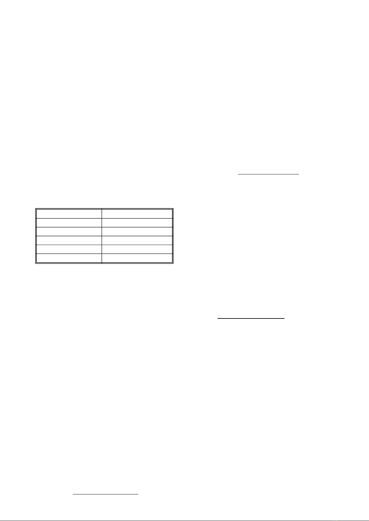
CODE ACCESS LEVEL
random L-0
157 L-1
314 L-2
628 L-3
942 L-4
Working time setting mode (L-0)
Display brightness setting mode (L-0)
Calibration mode (L-1)
Preheating time setting mode (L-2)
Preheating temperature setting mode (L-3)
Preset temperature limit setting mode (L-4)
Calibration mode (CAL.) L-1 - activated after holding
down the "ON / OFF" button. The display shows the
calibrated value of temperature. Display unit: °C.
Preheating time setting mode (P.tI.) L-2 - activated
after holding down the "ON / OFF" button. The display
shows the preheating time, counting from the moment
of switching on, during which the controller performs
initial heating and maintains the initial heating
temperature programmed by the manufacturer. The
indication "OFF" means the preheating function is not
active.
Display unit: minutes. When pre-heating is activated,
the controller displays "HC2" during startup.
Preheating temperature setting mode (P.tE.) L-3 -
activated after long pressing the "ON / OFF" button. The
display shows the value of the preset preheating
temperature. Display unit: °C.
Preset temperature limit setting mode
(L.t.h.) L-4 - activated after long pressing the
"ON / OFF" button. The display shows the
maximum value of the set temperature that
can be set. Display unit: °C.
4 – minus “-” button
Operation mode - Pressing the button decreases the preset
temperature value. During preheating, the possibility of
changing the preset temperature setting is blocked.
Working time setting mode - pressing the button decreases
the time after which the thermostat is automatically turned off.
Display brightness setting mode - pressing the button
decreases the display brightness.
Calibration mode - pressing the button decreases the value of
the indicated (calibrated) temperature.
Preheating time setting mode - pressing the button reduces
the time after which the thermostat automatically switches from
the preliminary heating phase to the work heating phase.
Preheating temperature setting mode - pressing the button
decreases the value of the preset temperature that is
maintained during preliminary heating.
Preset temperature limit setting mode - pressing the button
decreases the value of the maximum preset temperature that
can be set.
5 – p lus „+” button
Operation mode - Pressing the button increases the preset
temperature value. During preheating, the possibility of
changing the preset temperature setting is blocked.
Working time setting mode - pressing the button increases
the time after which the thermostat is automatically turned off.
Display brightness setting mode - pressing the button
increases the display brightness.
Calibration mode - pressing the button increases the value of
the indicated (calibrated) temperature.
Preheating time setting mode - pressing the button increases
the time after which the thermostat automatically switches from
the preliminary heating phase to the work heating phase.
Preheating temperature setting mode - pressing the button
increases the value of the preset temperature that is
maintained during preliminary heating.
Preset temperature limit setting mode - pressing the button
increases the value of the maximum preset temperature that
can be set.
6 – „ON/OFF” button
Pressing the button alternately turns the controller ON and
OFF. In the OFF state, the controller behaves like a
thermometer. In the ON state, the controller enables and
disables the heater control relay to maintain the
temperature set by the user.
Longer pressing and holding the button and then releasing
the button activates the working time setting mode,
indicated by the displayed message (Pro.). In this mode,
using the "+" and "-" buttons adjust the time after which the
controller will automatically turn off. To exit from this mode
and to confirm settings short press the "ON / OFF" button.
Press and hold and then release the button to enter the
display brightness setting mode – which is indicated by
(d.br.) message. In this mode, use the "+" and "-" buttons,
to set the brightness of the display. To exit this mode and to
confirmo settings short press the "ON / OFF" button.
Press and hold and then release the button to enter the
calibration mode, which is indicated by the displayed
message (CAL.). In this mode, use the "+" and "-" buttons,
to adjust the displayed temperature value. To exit this mode
and to confirm the calibration settings short press the "ON /
OFF" button. Note - the controller is factory calibrated.
Press and hold and then release the button to activate the pre-

heating time setting mode, which is indicated by the
displayed message (P.tI.). In this mode, use the "+"
and "-" buttons, to define the time after which the
controller automatically switches from the preheating
phase to the work heating phase. Message "OFF"
means that the pre-heating function is inactive. To
exit this mode and to confirm settings short press of
the "ON / OFF" button.
Press and hold and then release the button to
activate the pre-heating temperature setting mode,
which is indicated by the displayed message (P.tE.).
In this mode, by use the "+" and "-" buttons to define
the temperature that will be maintained during the
preliminary heating. To exit this mode and to confirm
settings short press the "ON / OFF" button.
Press and hold and then release the button to
activate the preset temperature limit setting mode,
which is indicated by the displayed message (L.t.h.).
In this mode, use the "+" and "-" buttons to set the
upper limit of the preset temperature setting. To exit
this mode and to confirm setting short press the
"ON / OFF" button.
Note - all settings and the controller operation
status (on or off) are stored in the permament
memory.
4.3. Troubleshooting
The HC1 controller is equipped with advanced error
detection algorithms. Detection of any error engages
the emergency stop function and the error report
screen is displayed. To remove the error report
screen turn off the power, remove the source of the
error and turn on the controller again.
ERROR CODE DESCRIPTION
(E-0) CPU
STATUS
Main processor fault.
(E-3) T < Tmin T1 temperature too low.
(E-4) T > Tmax T1 temperature.
(E-5) Przycisk - „-„ button fault (or stuck)
(E-6) Przycisk + „+” button fault (or stuck)
(E-7) Przycisk ON/
OFF
„ON/OFF” button fault
(or stuck)
5. Storage
Clean and dry the unit thoroughly after use.
If the device has been moved from a cold
room to a room with a higher temperature,
before switching on wait until it reaches the
ambient temperature and all condensation
water evaporates.
Store the device in a dry and frost-free
room.
Do not use the device when the ambient
temperature is below 5ºC.
An additional technical check should be carried out
periodically, and if any defects are found, please contact the
manufacturer.
6. Cleaning and maintenance
IMPROTANT
Unplug the device from the power supply outlet
before performing any maintenance!
Before first use and after finishing work the equipment must be
thoroughly cleaned and dried.
While cleaning ensure the safety of all electrical components like
motors and controller panels (for the time of washing cover them
with waterproof fabric or plastic film).
An additional technical check should be carried out before the
start of the pollen harvesting season, and if any defects are
found, please contact the manufacturer.
7. Waste disposal and environmental protection
The used product must be disposed in accordance with the local
regulations. Return the device to a collection point from where it
can be submitted for environmentally compatible recycling.
The consumer has the right to return used equipment directly to
the manufacturer's distribution network, free of charge, while
replacing it with a new unit as long as the used device is of the
same kind and same application as the newly purchased device.
8. Warranty
The product purchased from the Lyson Company is
covered by a manufacturer's warranty. The warranty
period is 24 months from the date of purchase.
All purchased products come with receipts or VAT
invoices.
Warranty details at:
www.lyson.com.pl
This manual suits for next models
1
Table of contents
Other LYSON Industrial Equipment manuals

LYSON
LYSON W3207 User manual

LYSON
LYSON W20087 User manual

LYSON
LYSON Vap-Pro Diffusor 12V User manual

LYSON
LYSON Optima User manual

LYSON
LYSON C-01 User manual

LYSON
LYSON W20210S User manual

LYSON
LYSON W20970 User manual

LYSON
LYSON Optima User manual

LYSON
LYSON Minima W2092S User manual

LYSON
LYSON Premium FI 500 MM User manual