manuals.online logo
Brands
  1. Home
  2. •
  3. Brands
  4. •
  5. M-system
  6. •
  7. Transmitter
  8. •
  9. M-system 10JRE User manual

M-system 10JRE User manual

5-2-55, Minamitsumori, Nishinari-ku, Osaka 557-0063 JAPAN
Phone: +81(6)6659-8201 Fax:
+81(6)6659-8510 E-mail: info@m-system.co.jp
EM-0815 Rev.6 P. 1 / 4
INSTRUCTION MANUAL
4-WIRE RTD TRANSMITTER
(eld-programmable) MODEL 10JRE
BEFORE USE ....
Thank you for choosing M-System. Before use, please check
contents of the package you received as outlined below.
If you have any problems or questions with the product,
please contact M-System’s Sales Office or representatives.
■PACKAGE INCLUDES:
Signal conditioner ...............................................................(1)
■MODEL NO.
Confirm Model No. marking on the product to be exactly
what you ordered.
■INSTRUCTION MANUAL
This manual describes necessary points of caution when
you use this product, including installation and connection,
hardware setting, and basic maintenance procedures.
When you need to change software settings, please refer to
the Operation Manual for Model PU-2x (EM-9255), Section
A.
POINTS OF CAUTION
■POWER INPUT RATING & OPERATIONAL RANGE
•Locate the power input rating marked on the product and
confirm its operational range as indicated below:
24 V DC ±10%, approx. 60 mA with voltage output
approx. 90 mA with current output
■GENERAL PRECAUTIONS
•Before you remove the unit or mount it, turn off the power
supply and input signal for safety.
■ENVIRONMENT
•Indoor use.
•When heavy dust or metal particles are present in the
air, install the unit inside proper housing with sufficient
ventilation.
•Do not install the unit where it is subjected to continuous
vibration. Do not subject the unit to physical impact.
•Environmental temperature must be within -5 to +55°C
(23 to 131°F) with relative humidity within 30 to 90% RH
in order to ensure adequate life span and operation.
■WIRING
•Do not install cables close to noise sources (relay drive
cable, high frequency line, etc.).
•Do not bind these cables together with those in which
noises are present. Do not install them in the same duct.
■AND ....
•The unit is designed to function as soon as power is sup-
plied, however, a warm up for 10 minutes is required for
satisfying complete performance described in the data
sheet.
COMPONENT IDENTIFICATION
Body
(side)
Terminal Cover
Modular Jack
Specifications
Connection Diagram
INSTALLATION
Use Standard Rack (model: 10BXx).
10JRE
5-2-55, Minamitsumori, Nishinari-ku, Osaka 557-0063 JAPAN
Phone: +81(6)6659-8201 Fax:
+81(6)6659-8510 E-mail: info@m-system.co.jp
EM-0815 Rev.6 P. 2 / 4
TERMINAL CONNECTIONS
Connect the unit as in the diagram below or refer to the connection diagram on the unit side.
■EXTERNAL DIMENSIONS unit: mm (inch)
130 (5.12)
3 (.12)
51 (2.01)
82 (3.23)
2–4.3 (.17) dia.
MTG HOLE
TERMINAL COVER
7–M3.5 SCREW
8 (.31)
91 (3.58)
99 (3.90 )
25 (.98)
12
3
56
78
PU-2x
+
–
OUTPUT
7
8
OUTPUT
POWER
2
1
RTD
3
5
CONNECTOR
MODULAR JACK
■CONNECTION DIAGRAM
10JRE
5-2-55, Minamitsumori, Nishinari-ku, Osaka 557-0063 JAPAN
Phone: +81(6)6659-8201 Fax:
+81(6)6659-8510 E-mail: info@m-system.co.jp
EM-0815 Rev.6 P. 3 / 4
CHECKING
1 ) Terminal wiring: Check that all cables are correctly
connected according to the connection diagram.
2 ) Power input voltage: Check voltage supplied to the rack
(model: 10BXx). For the DC power source, be sure that
the ripple level is within 10% p-p.
3 ) Input: Check that the input signal is within 0 – 100%
of the full-scale.
(With 20°C or 68°F, approx. 1.1V should read.)
If RTD wires are broken, the output goes over 100% (below
0% with downscale protection) due to burnout protection
function. Check leadwires in such a case.
4 ) Output: Check that the load resistance meets the de-
scribed specifications.
ADJUSTMENT PROCEDURE
This unit is calibrated at the factory to meet the ordered
specifications, therefore you usually do not need any cali-
bration, unless you need to match the signal to a receiving
instrument or conduct regular calibration.
Zero and span are adjusted with using the Programming
Unit (model: PU-2x).
Refer to the Operation Manual for Model PU-2x for expla-
nations how to use the programmer.
■WARNING ON USE OF THE PROGRAMMING UNIT
•Be sure to disconnect the Programming Unit before you
turn on/off power supply to the unit.
•The output signal is held when the Programming Unit is
connected. You need to disconnect when confirming cur-
rent output values.
■HOW TO CALIBRATE THE OUTPUT SIGNAL
Use a signal source and measuring instruments of sufficient
accuracy level. Turn the power supply on and warm up for
more than 10 minutes.
• Fine Output Calibration
Using the Programming Unit (ITEM 19, 20)
ITEM 19 is for Zero, and ITEM 20 is for Span.
1 ) Turn the unit into Program mode (ITEM 01).
2 ) Apply simulated 0% input. Increase/decrease values
(default: 0%) at ITEM 19 until the output signal is cali-
brated to actual 0%.
3 ) Apply simulated 100% input. Increase/decrease value
(default: 100%) at ITEM 20 until the output signal is
calibrated to actual 100%.
4 ) Apply simulated 0% input again and check 0% output.
5 ) When 0% value is changed, repeat the above procedure
2) - 4).
The 0% value may be shifted when the output span is
greater than the input span (gain > 1).
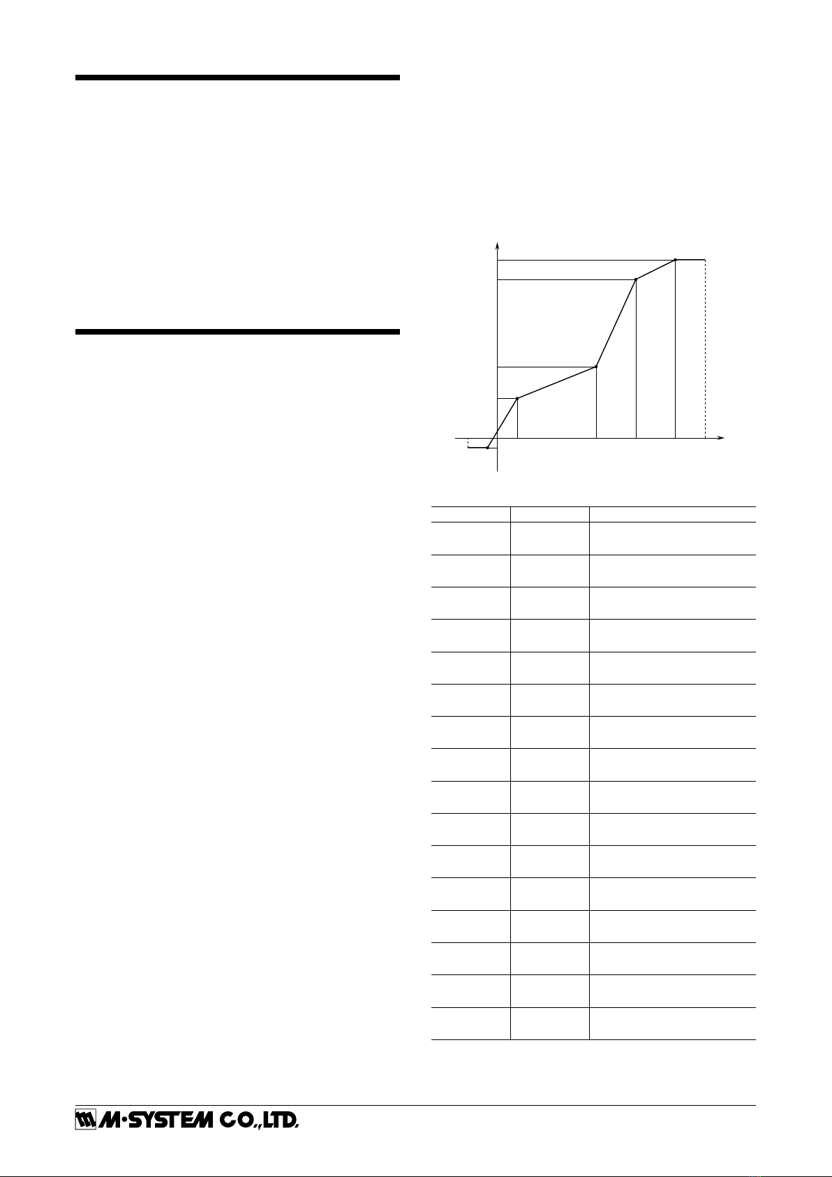
• Using Linearization Table
Please have the PU-2x Operation Manual ready at hand.
Max. 16 calibration points defined by sets of input and out-
put values can be programmed. Use only necessary number
of points, arranged in order from the smallest input value.
Enable use of the linearization table (ITEM 10: Pm-2:
curved) in order to activate the settings.
X (nn) : Input Signal in %
Y (nn) : Output Signal in %
X or Y : -15.00 to +115.00%
-15% 0
X01
X02 X03 X04 X05 +115%
Y01
Y02
Y03
Y04
+100% Y05
INPUT
OUTPUT
[GROUP 01]
ITEM MDFY. DATA EXAMPLE
60 P X (01) : XXX.XX
61 P Y (01) : XXX.XX
62 P X (02) : XXX.XX
63 P Y (02) : XXX.XX
64 P X (03) : XXX.XX
65 P Y (03) : XXX.XX
66 P X (04) : XXX.XX
67 P Y (04) : XXX.XX
68 P X (05) : XXX.XX
69 P Y (05) : XXX.XX
70 P X (06) : XXX.XX
71 P Y (06) : XXX.XX
72 P X (07) : XXX.XX
73 P Y (07) : XXX.XX
74 P X (08) : XXX.XX
75 P Y (08) : XXX.XX
76 P X (09) : XXX.XX
77 P Y (09) : XXX.XX
78 P X (10) : XXX.XX
79 P Y (10) : XXX.XX
80 P X (11) : XXX.XX
81 P Y (11) : XXX.XX
82 P X (12) : XXX.XX
83 P Y (12) : XXX.XX
84 P X (13) : XXX.XX
85 P Y (13) : XXX.XX
86 P X (14) : XXX.XX
87 P Y (14) : XXX.XX
88 P X (15) : XXX.XX
89 P Y (15) : XXX.XX
90 P X (16) : XXX.XX
91 P Y (16) : XXX.XX
Modication Code
S: Modifiable at any time.
P: Modifiable only when the MAINTENANCE SWITCH is in
the “PRG” mode.
10JRE
5-2-55, Minamitsumori, Nishinari-ku, Osaka 557-0063 JAPAN
Phone: +81(6)6659-8201 Fax:
+81(6)6659-8510 E-mail: info@m-system.co.jp
EM-0815 Rev.6 P. 4 / 4
PROGRAMMABLE ITEMS
The following items can be monitored and programmed. For detailed explanations, please refer to the Operation Manual for
Model PU-2x (EM-9255), Section A.
[GROUP 01]
ITEM MDFY. DATA INPUT DISPLAY CONTENTS
01 S MAINTENANCE SWITCH (lock command)
0 MTSW: MON.MODE MONITOR mode: data monitoring only
1 MTSW: PRG.MODE PROGRAM mode: “P” marked data modifiable
02 P Alphabets & No. TG: XXXXXXXXXX Tag name entry (10 characters max.)
03
05
P
D
Number (%)
No input
OUTPER XXX.XX
INPPER XXX.XX
Output status monitor (%) & simulation output
Input status monitor (%)
10 P LINEARIZATION
41 Pm-1: straight Without
42 Pm-2: curved With (ITEM 60 to 91 for data input)
19 P Percentage FINZER Fine zero adjustment
Initial status shows actual bias (%).
When data is entered, output (%) is shown.
20 P Percentage FINSPN Fine span adjustment
Initial status shows actual gain (%).
When data is entered, output (%) is shown.
LINEARIZATION TABLE
60 P Percentage X (01) : XXX.XX Input 1
61 P Percentage Y (01) : XXX.XX Output 1
: :   :  :  :
: :   :  :  :
91 P Percentage Y (16) : XXX.XX Output 16
Modication Code
D: No modification (writing) possible. Used only for monitoring (reading).
S: Modifiable at any time.
P: Modifiable only when the MAINTENANCE SWITCH is in the “PRG” mode.
MAINTENANCE
Regular calibration procedure is explained below:
■CALIBRATION
Warm up the unit for at least 10 minutes. Apply 0%, 25%,
50%, 75% and 100% input signal. Check that the output
signal for the respective input signal remains within accu-
racy described in the data sheet. When the output is out of
tolerance, recalibrate the unit according to the “ADJUST-
MENT PROCEDURE” explained earlier.
LIGHTNING SURGE PROTECTION
M-System offers a series of lightning surge protector for
protection against induced lightning surges. Please contact
M-System to choose appropriate models.

Other M-system Transmitter manuals

M-system W2XR User manual

M-system

M-system W2XR User manual

M-system M2ADS User manual

M-system

M-system M2ADS User manual

M-system 6BR User manual

M-system

M-system 6BR User manual

M-system W2SP User manual

M-system

M-system W2SP User manual

M-system F2VS User manual

M-system

M-system F2VS User manual

M-system LC User manual

M-system

M-system LC User manual

M-system Mini-M M2RS1 User manual

M-system

M-system Mini-M M2RS1 User manual

M-system 10VS User manual

M-system

M-system 10VS User manual

M-system 35mm User manual

M-system

M-system 35mm User manual

M-system M3LM User manual

M-system

M-system M3LM User manual

M-system 6M User manual

M-system

M-system 6M User manual

M-system KP User manual

M-system

M-system KP User manual

M-system 6TS1 User manual

M-system

M-system 6TS1 User manual

M-system M5XCRS User manual

M-system

M-system M5XCRS User manual

M-system Mini-M M2AMS User manual

M-system

M-system Mini-M M2AMS User manual

M-system M3LPA User manual

M-system

M-system M3LPA User manual

M-system 6BVS User manual

M-system

M-system 6BVS User manual

M-system 17PE User manual

M-system

M-system 17PE User manual

M-system W2XT User manual

M-system

M-system W2XT User manual

M-system M5YV User manual

M-system

M-system M5YV User manual

M-system 10JPA User manual

M-system

M-system 10JPA User manual

M-system W2RS1 User manual

M-system

M-system W2RS1 User manual

M-system LC2 User manual

M-system

M-system LC2 User manual

M-system M2VF User manual

M-system

M-system M2VF User manual

Popular Transmitter manuals by other brands

Honeywell SmartLine ST700 user guide

Honeywell

Honeywell SmartLine ST700 user guide

Compur Statox 506 Getting started

Compur

Compur Statox 506 Getting started

Advantech SSPB-3000C Installation and operation manual

Advantech

Advantech SSPB-3000C Installation and operation manual

AMG AMG5611R instruction sheet

AMG

AMG AMG5611R instruction sheet

Nautel NX200 Installation and operation manual

Nautel

Nautel NX200 Installation and operation manual

Lodar 92320 quick start guide

Lodar

Lodar 92320 quick start guide

Kramer TP-594Txr quick start guide

Kramer

Kramer TP-594Txr quick start guide

ATI Technologies D12 EX-IR Series O & M Manual

ATI Technologies

ATI Technologies D12 EX-IR Series O & M Manual

MELICONI AV 100 Plus User instructions

MELICONI

MELICONI AV 100 Plus User instructions

KLAY-INSTRUMENTS PERAMIC instruction manual

KLAY-INSTRUMENTS

KLAY-INSTRUMENTS PERAMIC instruction manual

iKarus NG-6 operating instructions

iKarus

iKarus NG-6 operating instructions

ACM TX PLUS 12D manual

ACM

ACM TX PLUS 12D manual

Multiplex COCKPIT SX M-LINK Supplementary operating instructions

Multiplex

Multiplex COCKPIT SX M-LINK Supplementary operating instructions

DITEC ZEN2 Series user manual

DITEC

DITEC ZEN2 Series user manual

Rice Lake SCT-1SX-MODBUS TCP/IP quick start guide

Rice Lake

Rice Lake SCT-1SX-MODBUS TCP/IP quick start guide

BURK Technology PlusConnect GatesAir Sigma Installation and operation manual

BURK Technology

BURK Technology PlusConnect GatesAir Sigma Installation and operation manual

RadioLink AT9 quick start guide

RadioLink

RadioLink AT9 quick start guide

Sontay GS-AQ521 quick start guide

Sontay

Sontay GS-AQ521 quick start guide

manuals.online logo
manuals.online logoBrands
  • About & Mission
  • Contact us
  • Privacy Policy
  • Terms and Conditions

Copyright 2025 Manuals.Online. All Rights Reserved.