manuals.online logo
Brands
  1. Home
  2. •
  3. Brands
  4. •
  5. M-system
  6. •
  7. Transmitter
  8. •
  9. M-system 27PM User manual

M-system 27PM User manual

5-2-55, Minamitsumori, Nishinari-ku, Osaka 557-0063 JAPAN
Phone: +81(6)6659-8201 Fax: +81(6)6659-8510 E-mail: info@m-system.co.jp
EM-7657-A Rev.2 P. 1 / 3
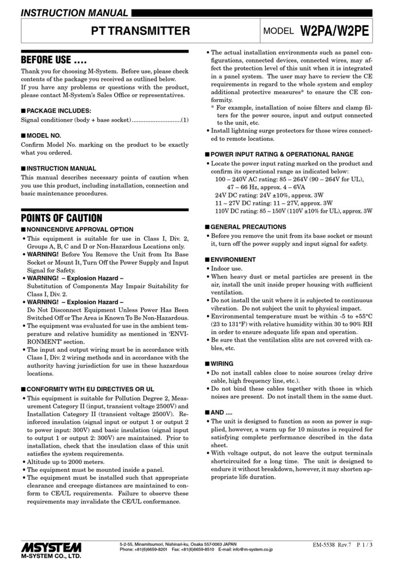
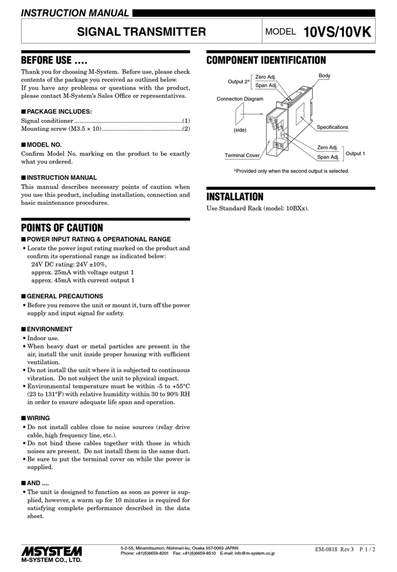
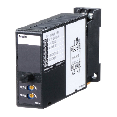
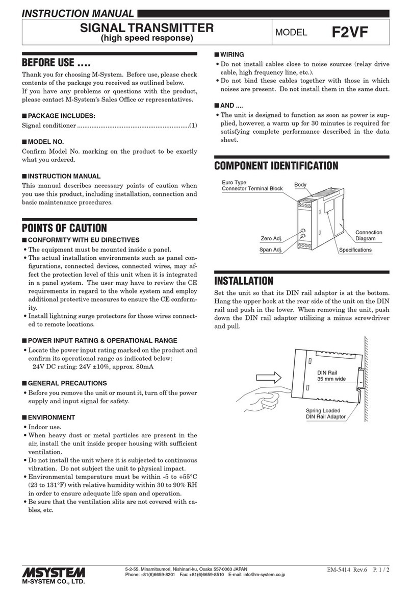
INSTRUCTION MANUAL
POTENTIOMETER TRANSMITTER
(PC programmable) MODEL 27PM
BEFORE USE ....
Thank you for choosing M-System. Before use, please check
contents of the package you received as outlined below.
If you have any problems or questions with the product,
please contact M-System’s Sales Office or representatives.
■PACKAGE INCLUDES:
Signal conditioner ...............................................................(1)
■MODEL NO.
Confirm Model No. marking on the product to be exactly
what you ordered.
■INSTRUCTION MANUAL
This manual describes necessary points of caution when
you use this product, including installation, connection and
basic maintenance procedures.
POINTS OF CAUTION
■CONFORMITY WITH EU DIRECTIVES
• The actual installation environments such as connected
devices and connected wires may affect the protection
level of this unit when it is integrated in a panel system.
The user may have to review the CE requirements in re-
gard to the whole system and employ additional protec-
tive measures to ensure the CE conformity.
■GENERAL PRECAUTIONS
• Before you remove the module, turn off the power supply
and input signal for safety.
■ENVIRONMENT
• When heavy dust or metal particles are present in the air,
install the module inside proper housing with sufficient
ventilation.
• Do not install the module where it is subjected to con-
tinuous vibration. Do not subject the module to physical
impact.
• Environmental temperature must be within -40 to +85°C
(-40 to +185°F) with relative humidity within 0 to 95%
RH in order to ensure adequate life span and operation.
■WIRING
• Do not install cables close to noise sources (relay drive
cable, high frequency line, etc.).
• Do not bind these cables together with those in which
noises are present. Do not install them in the same duct.
■AND ....
• The module is designed to function as soon as power is
supplied, however, a warm up for 10 minutes is required
for satisfying complete performance described in the data
sheet.
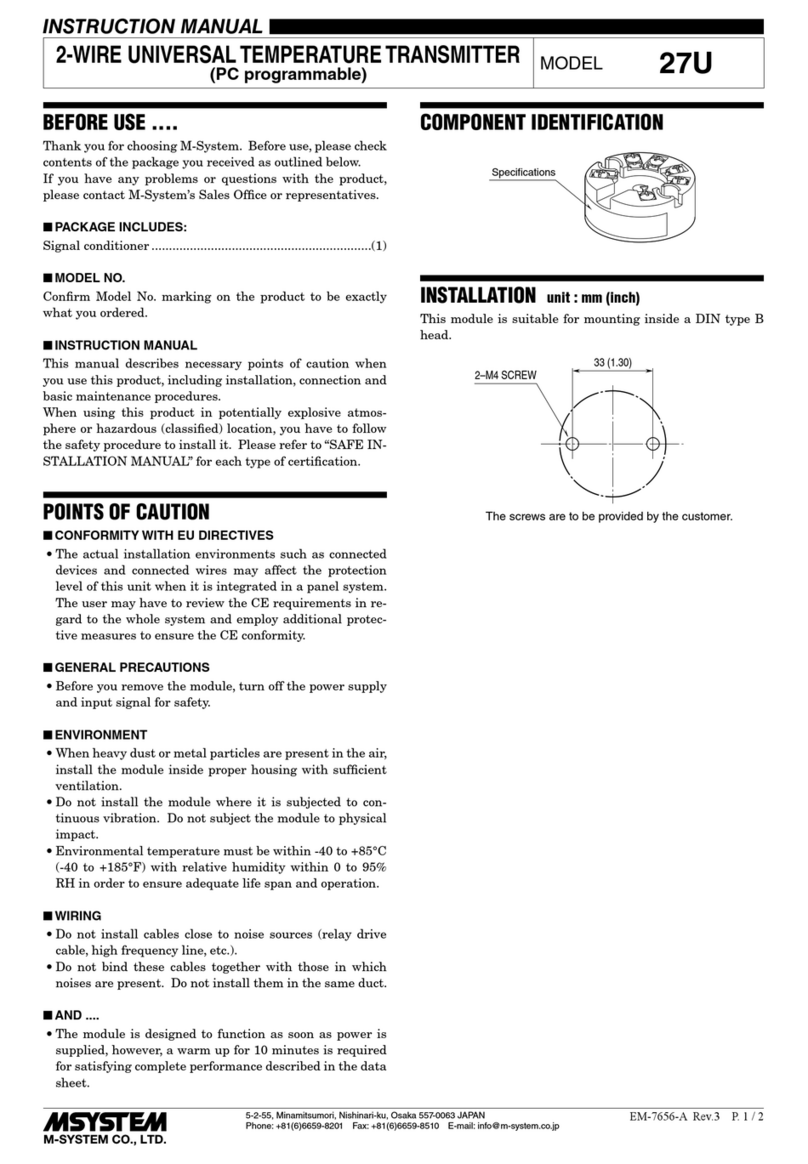
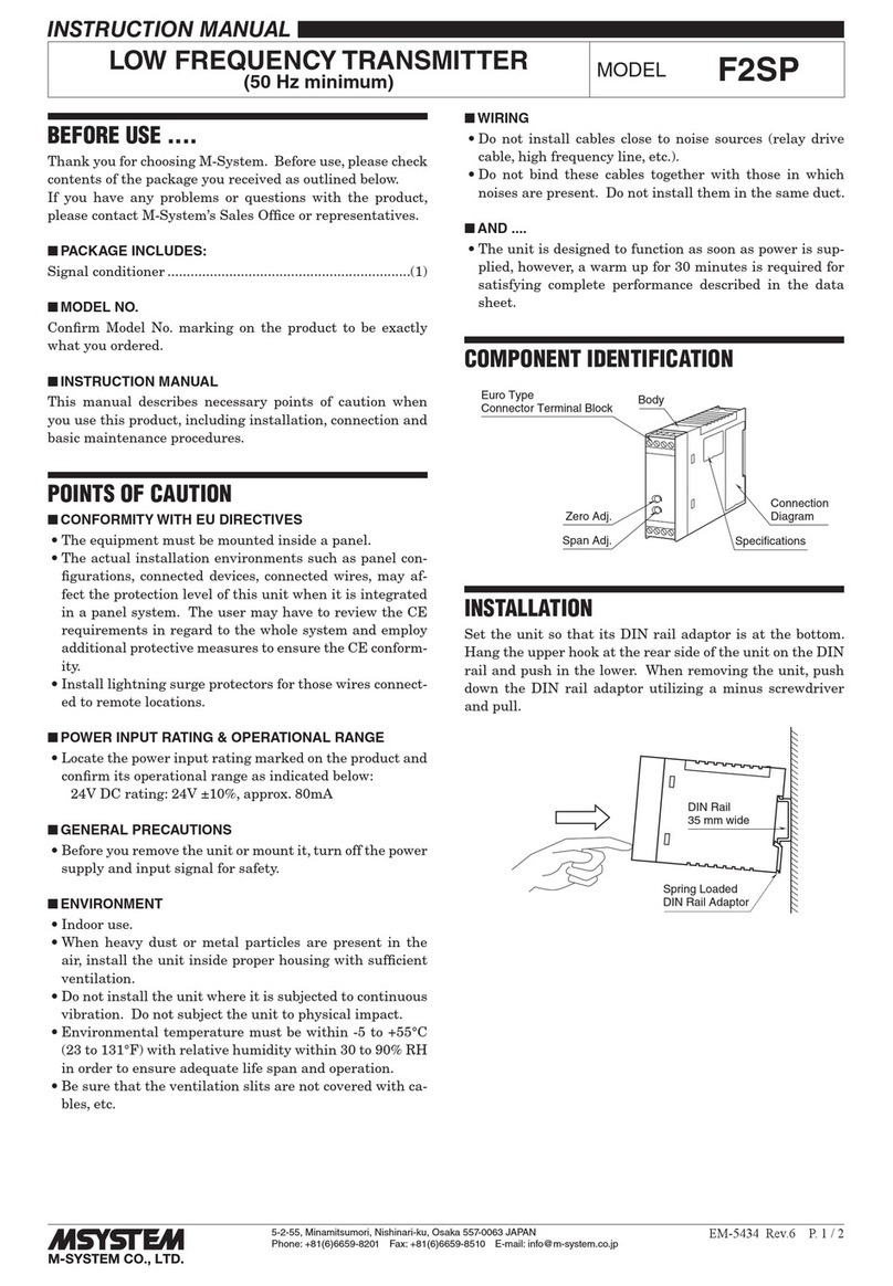
COMPONENT IDENTIFICATION
Specifications
INSTALLATION unit : mm (inch)
This module is suitable for mounting inside a DIN type B
head.
33 (1.30)
2–M4 SCREW
The screws are to be provided by the customer.
27PM
5-2-55, Minamitsumori, Nishinari-ku, Osaka 557-0063 JAPAN
Phone: +81(6)6659-8201 Fax: +81(6)6659-8510 E-mail: info@m-system.co.jp
EM-7657-A Rev.2 P. 2 / 3
TERMINAL CONNECTIONS
Connect the module as in the diagram below.
■EXTERNAL DIMENSIONS unit : mm (inch)
44 (1.73) dia.
6.3
(.25)
33 (1.30) 6 (.24) dia.
16.5 (.65)
6–M3 SCREW
2–4.5 (.18) dia.
MTG HOLE
20.7 (.81)
19.5 (.77)
12.7 (.5)
14
32
–+
7.6 (.30) dia.
■CONNECTION DIAGRAM
LOAD
OUTPUT
24V DC
4 – 20mA DC
*1
POTENTIOMETER
*1. Limited to 250 – 500Ω when using the communication to configure
the module.
+
–
4
1
3
3
2
1
max.
min.
+
–
WIRING INSTRUCTIONS
■SCREW TERMINAL
Torque: 0.5 N·m
CHECKING
1) Terminal wiring: Check that all cables are correctly con-
nected according to the connection diagram.
2) Input: Check that the voltage between terminal 3 – 4 is
within 0 – 100% of full-scale.
If the potentiometer wires are broken, the output goes
over 100% (below 0% with downscale) due to burnout
function. Check leadwires in such a case.
3) Output: Check that the load is within the permissible
limit including wiring resistance.
Load Resistance (Ω) = Supply Voltage (V) – 9 (V)
0.023 (A)
(including leadwire resistance)
ADJUSTMENT PROCEDURE
To calibrate the signal to match with a receiving instru-
ment or to change the factory-set configurations, use the PC
Configurator software installed on a Windows PC via the
Bell202 Modem (model COP-HU).
The PC Configurator software is downloadable at M-Sys-
tem’s web site: http://www.m-system.co.jp
LIGHTNING SURGE PROTECTION
M-System offers a series of lightning surge protector for
protection against induced lightning surges. Please contact
M-System to choose appropriate models.
27PM
5-2-55, Minamitsumori, Nishinari-ku, Osaka 557-0063 JAPAN
Phone: +81(6)6659-8201 Fax: +81(6)6659-8510 E-mail: info@m-system.co.jp
EM-7657-A Rev.2 P. 3 / 3
FUNCTION MONITOR LED (option /M)
■FUNCTION MONITOR LED
32
41
–+
Function
Monitor LED
■INPUT MONITOR: The input 0 – 100% is converted into a combination of 1-second (1 unit) and 0.25-second (0.2 unit) cycled
pulses. 1 unit corresponds to 25%, while 0.2 unit corresponds to 5%. 0% equals to 1 unit, while 100% cor-
responds to 5 units. The input % is represented in the total number of 1-unit pulses and 0.2-unit pulses,
repeated in the sequence of ‘1-unit pulses ––> 0.2-unit pulses ––> OFF for 1 second or more.’
[Examples]
25% = 2 units
30% = 2.2 units
45% = 2.8 units
50% = 3 units
100% = 5 units
0% = 1 unit
≥1 second
1 UNIT
25%
ON OFF
1 sec.
0.2 UNIT
5%
0.25 sec.
■ERROR MONITOR: Indicates the transmitter’s error status.
Lower overrange: The input signal is lower than the out-
put’s lower range limit.
2 sec. cycle
0.125 sec. OFF
Upper overrange: The input signal is higher than the out-
put’s upper range limit.
0.125 sec. OFF - ON - OFF
2 sec. cycle
Burnout: Sensor wire breakdown is detected.
0.125 sec. ON - OFF
Internal error: The CPU detects an internal error.
0.125 sec. ON - OFF - ON
1 sec. cycle

Other M-system Transmitter manuals

M-system Mini-M M2XRP2 User manual

M-system

M-system Mini-M M2XRP2 User manual

M-system 18KJV User manual

M-system

M-system 18KJV User manual

M-system W2RS User manual

M-system

M-system W2RS User manual

M-system W5RS User manual

M-system

M-system W5RS User manual

M-system M3LR User manual

M-system

M-system M3LR User manual

M-system F2RS User manual

M-system

M-system F2RS User manual

M-system M3SMS User manual

M-system

M-system M3SMS User manual

M-system 10JV User manual

M-system

M-system 10JV User manual

M-system JPA2 User manual

M-system

M-system JPA2 User manual

M-system M5MV User manual

M-system

M-system M5MV User manual

M-system 17PE User manual

M-system

M-system 17PE User manual

M-system M1EXS-2 User manual

M-system

M-system M1EXS-2 User manual

M-system W2SP User manual

M-system

M-system W2SP User manual

M-system 10TG User manual

M-system

M-system 10TG User manual

M-system 35mm User manual

M-system

M-system 35mm User manual

M-system 6AC User manual

M-system

M-system 6AC User manual

M-system F2VS User manual

M-system

M-system F2VS User manual

M-system M1EXV-4 User manual

M-system

M-system M1EXV-4 User manual

M-system M5RS User manual

M-system

M-system M5RS User manual

M-system Mini-M M2AC User manual

M-system

M-system Mini-M M2AC User manual

M-system M3LT User manual

M-system

M-system M3LT User manual

M-system Mini-M M2DU User manual

M-system

M-system Mini-M M2DU User manual

M-system Mini-M M2RS1 User manual

M-system

M-system Mini-M M2RS1 User manual

M-system LC User manual

M-system

M-system LC User manual

Popular Transmitter manuals by other brands

WIKA CPT-2 series operating instructions

WIKA

WIKA CPT-2 series operating instructions

Sennheiser EK 2000 IEM Specifications

Sennheiser

Sennheiser EK 2000 IEM Specifications

ADTEK ST-VA Operation manual

ADTEK

ADTEK ST-VA Operation manual

Comunello R-CONTROL instruction manual

Comunello

Comunello R-CONTROL instruction manual

Scosche FMTD10 FMFREQ manual

Scosche

Scosche FMTD10 FMFREQ manual

Walkera Wk-2402A user manual

Walkera

Walkera Wk-2402A user manual

AVGear AVG-HDWP70TX-IR user manual

AVGear

AVGear AVG-HDWP70TX-IR user manual

Crystal Vision Vision FTX-VF user manual

Crystal Vision

Crystal Vision Vision FTX-VF user manual

Comnet FVT4014SHR Installation and operation manual

Comnet

Comnet FVT4014SHR Installation and operation manual

Doro HearPlus 322wra instruction manual

Doro

Doro HearPlus 322wra instruction manual

Hides HV-310 Quick installation guide

Hides

Hides HV-310 Quick installation guide

Active-semi PAC5220WP WPC A11 5V user guide

Active-semi

Active-semi PAC5220WP WPC A11 5V user guide

Velleman AVMOD17 quick guide

Velleman

Velleman AVMOD17 quick guide

Jamara FCX6 Pro Tel Instruction

Jamara

Jamara FCX6 Pro Tel Instruction

Amphony 1520 Product information

Amphony

Amphony 1520 Product information

Nice MYGO2BD Instructions and warnings for installation and use

Nice

Nice MYGO2BD Instructions and warnings for installation and use

Datcon DT1310 Series operating instructions

Datcon

Datcon DT1310 Series operating instructions

R.V.R. Elettronica GPSRXNV-01 user manual

R.V.R. Elettronica

R.V.R. Elettronica GPSRXNV-01 user manual

manuals.online logo
manuals.online logoBrands
  • About & Mission
  • Contact us
  • Privacy Policy
  • Terms and Conditions

Copyright 2025 Manuals.Online. All Rights Reserved.