MAHA SA 2 Euro Manual

D1 E101BA1-GB09
Test Lane
Eurosystem / Profi-LON
for cars and vans
Roller Brake Tester Shock Absorber Tester Side-Slip-Tester
Operation & Maintenance
Manual
English

Eurosystem / Profi-LON
II D1 E101BA1-GB09
EDITION
Version 9 of the operating manual dated 17.07.2003
D1 E101BA1-GB09
Software Version 6.07
Profi-LON Software Version 1.54
© MAHA GMBH & CO. KG.
All rights reserved. Any reproductions of this document, partial or complete, are only allowed
with prior consent of MAHA GmbH & Co. KG.
All rights reserved in cases of patent granting or registration of design.
The contents of this version have been checked with great care. However, errors cannot be fully
excluded. Please contact MAHA should you find errors of any kind.
Subject to technical change without notice.
These instructions are intended for users with previous technical knowledge in the field of
vehicle testing technology as well as basic computer knowledge and MS-Windows operating
system application.
Windows and Windows for Workgroups is a registered trademark of the Microsoft-Corporation.
MANUFACTURER
MAHA Maschinenbau Haldenwang GmbH & Co. KG.
Hoyen 20
D-87490 Haldenwang/Allgäu
Telephone: 08374 / 585-0
Telefax: 08374/ 585-499
Internet: http://www.maha.de
e-mail: maha@maha.de
SERVICE
MAHA Maschinenbau Haldenwang GmbH & Co. KG.
- Service dept. -
Hoyen 20
D-87490 Haldenwang/Allgäu
Hotline: 08374 / 585 + extension
260 for brake testers, test lanes
280 for lifting technology
290 for performance testers, exhaust and air condidioning service equipment
Service: 08374 / 585-110 bis - 113, - 115
Telefax: 08374 / 585-491

Eurosystem / Profi-LON
D1 E101BA1-GB09 III
TABLE OF CONTENTS
1Description .............................................................................................................1.1
1.1 Introduction .................................................................................................................................1.1
1.2 Usage, Range of Application ......................................................................................................1.1
1.3 Installation...................................................................................................................................1.2
1.4 Software Update.........................................................................................................................1.2
1.4.1 Backup Data................................................................................................................1.2
1.5 Noise Emission...........................................................................................................................1.2
1.6 Display Cabinet Profi-LON..........................................................................................................1.3
1.6.1 Multi-Functional Display, Profi-LON............................................................................1.3
1.6.2 Digital Displays............................................................................................................1.4
1.7 Test Lane Floor Assemblies .......................................................................................................1.4
1.7.1 Side-Slip Tester...........................................................................................................1.5
1.7.2 Shock Absorber Tester / Suspension..........................................................................1.6
1.7.3 Brake Tester................................................................................................................1.7
1.8 Remote Control (Option).............................................................................................................1.9
1.8.1 Infrared Remote Control IFB3.....................................................................................1.9
1.9 Pedal Force Meter (Optional) ...................................................................................................1.10
1.10 Printer 1.10
1.11 Accessories...............................................................................................................................1.10
2Safety ......................................................................................................................2.1
2.1 Introduction .................................................................................................................................2.1
2.2 Safety Regulations for Commissioning.......................................................................................2.1
2.3 Safety Regulations during Operation..........................................................................................2.2
2.4 Safety Regulations for Service Work..........................................................................................2.2
2.5 Attention......................................................................................................................................2.2
2.6 Further Information .....................................................................................................................2.2
2.7 Combining the MAHA Test Lane with Accessories....................................................................2.3
2.8 Spare Parts.................................................................................................................................2.3
2.9 Safety Features...........................................................................................................................2.3
2.9.1 Emergency-Off (Optional) ...........................................................................................2.3
2.9.2 Lockable Main Switch..................................................................................................2.3
2.9.3 Sensor Rollers (Brake Tester).....................................................................................2.3
2.9.4 Pit Safety (Optional) ....................................................................................................2.3
2.9.5 Warning and Information Labels .................................................................................2.3
3Profi-LON Operation (with Multifunctional Display)............................................3.1
3.1 Introduction .................................................................................................................................3.1
3.2 Test Procedure ...........................................................................................................................3.2
3.2.1 Switching on the Test Lane.........................................................................................3.2
3.2.2 Test Procedure without Remote Control.....................................................................3.3
3.2.3 Exit Brake Tester & Repeat Test with Rear Axle ........................................................3.4
3.2.4 Exit Test Lane..............................................................................................................3.4
3.2.5 Test Procedure with Remote Control..........................................................................3.5
3.2.6 Exit the Test Lane........................................................................................................3.7
3.3 Final Evaluation (only with remote control).................................................................................3.8
3.3.1 Completion of Measurement .......................................................................................3.8
3.3.2 Re-Display of Measurement Values............................................................................3.9
3.3.3 Manual Weight Entry.................................................................................................3.10
3.3.4 Printout of Measurements .........................................................................................3.10
3.4 Ovality Test...............................................................................................................................3.11
3.4.1 Ovality test without Remote Control..........................................................................3.11
3.4.2 Ovality Test with Remote Control..............................................................................3.11
3.5 Single Wheel Test (Optional)....................................................................................................3.12
3.5.1 Brake Test –Single Wheel, without Remote Control................................................3.12

Eurosystem / Profi-LON
IV D1 E101BA1-GB09
3.5.2 Brake Test –Single Wheel Test with Remote Control..............................................3.13
3.6 Noise Investigation (Optional)...................................................................................................3.14
3.6.1 Manual Operation without Remote Control...............................................................3.14
3.6.2 Manual Operation with Remote Control....................................................................3.15
3.7 4-Wheel Drive (Optional) ..........................................................................................................3.16
3.7.1 Brake Test 4-Wheel Drive .........................................................................................3.16
3.7.2 ASR / ASD Test.........................................................................................................3.19
4Eurosystem Operation (PC Program)...................................................................4.1
4.1 Introduction .................................................................................................................................4.1
4.1.1 Start Eurosystem.........................................................................................................4.1
4.1.2 Main Menu...................................................................................................................4.2
4.1.3 Screen Elements.........................................................................................................4.2
4.1.4 Keyboard Usage..........................................................................................................4.4
4.1.5 Exit Program................................................................................................................4.5
4.2 Automatic Test Procedure ..........................................................................................................4.6
4.2.1 General Information.....................................................................................................4.6
4.2.2 Side-Slip Test..............................................................................................................4.7
4.2.3 Shock Absorber Test / Suspension Tester..................................................................4.8
4.2.4 Brake Test...................................................................................................................4.9
4.2.5 Visual Defects............................................................................................................4.12
4.2.6 Storage of the Test Values........................................................................................4.14
4.2.7 Prepare New Test......................................................................................................4.15
4.3 Customer Administration...........................................................................................................4.16
4.3.1 Enter New Customer and Store ................................................................................4.16
4.3.2 Allocate Customer to Vehicle ....................................................................................4.17
4.3.3 Taking Customers into the Queue.............................................................................4.18
4.3.4 Display (Load) Customer Data..................................................................................4.19
4.3.5 Change, Expand, Update Customer Data.................................................................4.20
4.3.6 Delete Customer Data...............................................................................................4.20
4.4 Re-Display of Measurements ...................................................................................................4.21
4.4.1 Brake Test.................................................................................................................4.23
4.4.2 Shock Absorber Test.................................................................................................4.26
4.4.3 Side-Slip Test............................................................................................................4.27
4.4.4 Speedometer Test.....................................................................................................4.27
4.4.5 Odometer Test...........................................................................................................4.27
4.4.6 Toe Angle Difference.................................................................................................4.28
4.4.7 4-Gas Test.................................................................................................................4.28
4.4.8 Diesel Emission Test.................................................................................................4.28
4.4.9 Headlight Tester........................................................................................................4.29
4.4.10 Visual Defects............................................................................................................4.29
4.4.11 Brake Fluid Test ........................................................................................................4.29
4.4.12 Noise Level Test........................................................................................................4.30
4.4.13 Wheel Alignment .......................................................................................................4.30
4.4.14 Performance Test......................................................................................................4.30
4.5 Vehicle Administration ..............................................................................................................4.31
4.5.1 Enter New Vehicle and Store ....................................................................................4.32
4.5.2 Display (Load) Vehicle Data......................................................................................4.34
4.5.3 Change, Expand, Update Vehicle Data ....................................................................4.34
4.5.4 Delete Vehicle ...........................................................................................................4.35
4.6 Administration / Office...............................................................................................................4.36
4.6.1 Database Administration ...........................................................................................4.36
4.6.2 Printer Menu..............................................................................................................4.40
4.6.3 Test Equipment .........................................................................................................4.41
4.6.4 AU-Quality Control (Emission Testing)......................................................................4.43
4.7 Miscellaneous ...........................................................................................................................4.44
4.7.1 Display LON Variables/Print......................................................................................4.44
4.7.2 Settings......................................................................................................................4.45
4.7.3 Password Menu.........................................................................................................4.52

Eurosystem / Profi-LON
D1 E101BA1-GB09 V
4.7.4 Diagnostic Menu........................................................................................................4.53
4.7.5 Customer Promotion..................................................................................................4.56
4.7.6 External Programs.....................................................................................................4.57
4.8 Additional Functions..................................................................................................................4.59
4.8.1 Single Wheel Test .....................................................................................................4.59
4.8.2 Noise Investigation....................................................................................................4.59
4.8.3 SA2D Measurement Mode........................................................................................4.62
4.8.4 4-Wheel Drive Mode - ASR/ASD Check ...................................................................4.62
4.8.5 Diesel-Emission Test with MDO2-LON.....................................................................4.67
4.8.6 5-Gas Test with MGT 5 .............................................................................................4.67
4.8.7 4 Gas Test with Eurogas-Module..............................................................................4.68
4.9 Section “Office“.........................................................................................................................4.72
5Maintenance / Troubleshooting ............................................................................5.1
5.1 Shock Absorber Tester / Suspension Tester..............................................................................5.1
5.2 Roller Brake Tester.....................................................................................................................5.2
5.3 Side-Slip Tester ..........................................................................................................................5.3
5.4 Error Codes / Error Messages on the Multifunctional Display....................................................5.5
5.5 Troubleshooting..........................................................................................................................5.6
5.5.1 Shock Absorber Tester / Suspension Tester ..............................................................5.6
5.5.2 General / Brake Tester................................................................................................5.6
5.5.3 Side-Slip Tester...........................................................................................................5.7
6Appendix.................................................................................................................6.1
6.1 System Variables........................................................................................................................6.1
6.2 Short Instructions........................................................................................................................6.9
6.3 Connection to External Software..............................................................................................6.11
6.3.1 Werbas and Vaudis...................................................................................................6.11
6.3.2 Eurotax-Schwacke (WIPS)........................................................................................6.11

Eurosystem / Profi-LON
D1 E101BA1-GB09 1.1
1 Description
1.1 Introduction
Eurosystem
The safety test lane Eurosystem uses modular design. It is easily expandable and has the
following function groups as standard equipment: side-slip tester, shock absorber tester, roller
brake tester. In addition all kinds of MAHA test equipment can be connected. Test equipment
from other manufacturers can be integrated in some instances.
PC and screen display as well as Eurosystem software are standard equipment. This test lane
specific software developed by MAHA is based on the Windows operating system. The
measurement values can be processed on your own computer network.
Measurement data can be stored with or without remote control and organized in databases. An
additional analogue display (pointer) can be used.
Extensive test lanes can be divided into sections which are also supported and organized by the
Eurosystem software. Customer and vehicle data are quickly available at every section by the
use of chip cards.
Profi-LON
The safety test lane Profi-LON uses modular design and is partly expandable. The following
function groups are standard equipment:
Side-slip tester
Shock absorber tester
Brake tester
The test lane is equipped with a multifunctional analogue display.
A remote control is necessary to store measurement data. Only the current measurement
values can be filed (stored) and called up again.
If the test lane is equipped with a printer the measurement values stored last can be printed out.
Profi Eurosystem
The safety test lane Profi Eurosystem is a smaller version of Eurosystem.
The connection of a PC with Eurosystem-Software to the test lane Profi-LON makes a Profi
Eurosystem out of Profi-LON. The measurement values of the functional groups mentioned
above can then be displayed on the screen. Simultaneously many of the program functions of
Eurosystem are available.
1.2 Usage, Range of Application
Eurosystem and Profi-LON were developed for the testing of cars and vans. Depending on the
equipment various vehicle functions such as brakes, shock absorbers, side-slip, exhaust values,
etc. can be tested.
Please see the current price list for equipment options.

Eurosystem / Profi-LON Description
1.2 D1 E101BA1-GB09
1.3 Installation
The test lane may only be installed and commissioned by MAHA service technicians or by
authorized service partners. MAHA regulations and instructions for installation and expansion of
the test lane must be complied with.
The manufacturer’s CE Conformity Certification becomes void when installation is done by
unqualified technicians. MAHA accepts no liability for damage caused by unqualified,
unauthorized installation. In addition, the manufacturer’s warranty is also void..
1.4 Software Update
An „empty“database is, in principle, supplied with every Eurosystem software.
1.4.1 Backup Data
Data backup can be carried out by every skilled and qualified employee.
All important data on the harddisk must be backed up before the update.
MAHA accepts no liability for lost data!
1.5 Noise Emission
The noise emission during a vehicle test results mainly from the vehicle’s engine. The noise
emission varies from vehicle to vehicle and cannot be attributed to the test stand.
Roller Brake Tester
The noise emission value created by the brake tester (roller drive) is less than 70 dB (A) in the
work area of the operational personnel.
Suspension Tester/Shock Absorber Tester
The noise emission value created by the test stand (oscillating test plates) is between 75 dB (A)
and 80 dB (A) in the work area of the operator (measurement date 99-12-06, type of measuring
device: Monacor SM-6).
Side-Slip Tester
The noise emission value created by the side-slip tester is less than 70 dB (A) in the work area
of the operator.

Description Eurosystem / Profi-LON
D1 E101BA1-GB09 1.3
1.6 Display Cabinet Profi-LON
A Mains Supply (ON) key'
B Lock
C Main switch
D Single wheel switch for brake tester and
shock absorber tester (if used without
remote control)
E Brake tester switch to select evaluation
program (Mahameter or percentage)
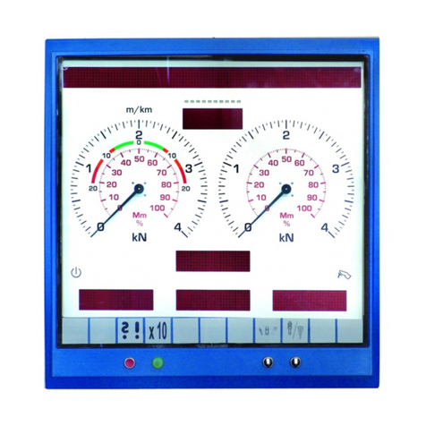
1.6.1 Multi-Functional Display, Profi-LON
The test lane Profi-LON is equipped with a multifunctional analogue display. The recorded
measurement values are displayed at the same moment that the test is done and remain on the
display for a certain time.
1 Imbalance display
2 Display for brake tester
3 READY lamp brake tester (yellow)
4 Lamp for measurement range expansion,
TRK mode, imbalance limit (optional)
5 Receiver control lamp (green), lights up
with reception
6 Receiver eye (white)
7 Multi-axle mode (optional)
8 Mains Supply (ON) lamp (white)
9 Display for shock absorber tester
10 Display for side-slip tester

Eurosystem / Profi-LON Description
1.4 D1 E101BA1-GB09
Multi-functional displays with measurement ranges from 0 to 40 kN are available. Measurement
values in expanded measurement ranges are shown by a burning lamp (Position 4) and must
be multiplied by factor two.
1.6.2 Digital Displays
Additionally, up to three LCD-displays can be integrated in the multifunctional display. They can
show various measurement values digitally:
Positions of the LCD displays Measurement values
Wheel weight
left/right
(if weighing device in
the roller set)
Axle weight
(centre)
1.7 Test Lane Floor Assemblies
Functional group
- Side-slip tester MINC Profi or
- Side-slip tester MINC I Euro
Functional group
- Shock absorber tester SA2 Euro or
- Suspension tester FWT 1 Euro
Functional group
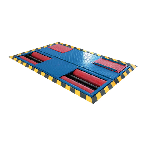
- Roller brake tester IW2 Euro Standard
- Roller brake tester IW2 Euro Profi
- Roller brake tester IW2 Euro RS-No. 2
- Roller brake tester IW2 Euro RS-No. 3
- Roller brake tester IW2 Euro RS-No. 4
- Roller brake tester IW2 Euro RS-No. 5

Description Eurosystem / Profi-LON
D1 E101BA1-GB09 1.5
1.7.1 Side-Slip Tester
Consists of the functional group MINC and the control module.
The MINC is a side-slip tester to check the vehicle tracking.
1.7.1.1 Measurement principle
While the vehicle passes over, the test plate is pressed to
the right or the left, depending on the wheel track. This
deviation is displayed in m/km.
New vehicles often have more toe-in. It must be offset against the measurement value.
Side-Slip Measurement Value Display
Color Side-slip deviation Result
Green 0 - 12 m/km OK
Orange 12 - 16 m/km Check wheel position
Red > 16 m/km Not OK
There are no official limit values for side-slip.
The measured values must therefore be interpreted by the inspector.
The sides-slip values are displayed on the left hand
measurement value scale of the analog display. The color
coding makes the evalution easier.
The wheel tracking can be positive or negative.
The track deviation in this example is (+) 5 m/km (positive
wheel position).
When the pointer moves to the right on the analog display this
indicates a positive track deviation. When the pointer moves
to the left on the analog display this indicates a negative track
deviation.
1.7.1.2 Technical Data
MINC 1 Euro MINC 1 Profi
Measurement range 0 - 20 m/km
Display accuracy 1 m/km
Axle load 3,0 t 2,0 t
Test plate dimensions 1020 x 460 x 80 mm

Eurosystem / Profi-LON Description
1.6 D1 E101BA1-GB09
1.7.2 Shock Absorber Tester / Suspension
Consists of the functional group SA 2 / FWT 1 Euro and the control module.
SA 2 and FWT 1 are used for judging the condition of a vehicle’s shock absorber..
Selection of the Evaluation Program
Profi-LON: Use this switch for shock absorber measurement to be displayed in
MAHA-Meter or percentage.
Eurosystem: Selection via software.
Single Wheel Program
Profi-LON: Use this switch to start the left or the right-hand test plate. Position “0“
means Standard, i.e. both plates vibrate, one after the other. This function is
suitable for noise detection on the vehicle body or suspension.
Eurosystem offers the single wheel switch over as standard equipment via
software.
1.7.2.1 Measurement Principle
Oscillations of the test vehicle wheels are induced via the test plates. The oscillations run
through various frequency ranges. The reaction of the tire-shock absorber functional group to
these oscillations is recorded.
Amplitude Evaluation Mm
The amplitudes of the measured oscillations at the resonance position are given for each wheel
in MAHA-Meter (Mm).
Percentage evaluation
This evaluation judges the quality of the vehicle’s shock absorber in percentage (%).
1.7.2.2 Technical Data
SA 2 Euro FWT 1 Euro
Tread max. 2200 mm
Tread min. 800 mm
Exciter stroke 9 mm 7.5 mm
Exciter frequency at 50 Hz rated frequency approx. 16 Hz
at 60 Hz rated frequency approx. 20 Hz
Measurement range max. 16 Hz; max. 100 mm Hub
Display accuracy 1 % of measurement range end value
Axle load normal/reinforce 1100 kg / 2000 kg
Voltage supply 230 V / 400 V, 3 Phases, 50 Hz
Fuse 16 A
Motor performance 2 x 1.3 kW 2 x 1.1 kW
Total weight approx. 500 kg
Dimensions floor assembly
(L x W x H) 2320 x 800 x 280 mm
Start of the test stand automatic at a load of more than 60 kg

Description Eurosystem / Profi-LON
D1 E101BA1-GB09 1.7
1.7.3 Brake Tester
Consists of the roller set, model IW 2, and the control module.
Single Wheel Program (Optional)
Profi-LON: Use this switch to select single wheel test (Left or Right). i.e. only the
left or the right-hand roller set is on. Position “0“means standard. i.e. both rollers
start as soon as the test stand is occupied and both sensor rollers are pressed.
Eurosystem offers the single wheel switch over as standard equipment via
software.
Lifting Bar (Optional)
The additional installation of a lifting bar makes drive-on and drive-off easier. The lifting bar is
operated either using a light barrier or manually using the keys <B> and <F9>.
Use a sturdy cover for protection of the brake tester if it is being driven over to reach a lift
positioned in front of it.
Weighing Device (Optional)
The total weight of the vehicle is required to calculate the percentage deceleration in the final
evaluation of the brake test. It makes sense to have an additional weighing device in the brake
tester if there is no shock absorber tester installed.
When the brake tester is equipped with a weighing device some displays and functions in the
final evaluation vary from the standard version. These variations are explained in section 3
“Operation“.
4 Wheel Drive Mode (Optional)
This mode means that vehicles with a rigid 4 wheel drive regulation or those with a Visco 4-
wheel drive regulation can have their brakes tested. Additionally it is possible to test ASR (Anti
Slip Regulation) and ASD (Automatic Differential Llock).
The exact RPM of the forward rotating rollers is recorded and transferred exactly to the reverse
rotating rollers. In this way power transmission to the second axle and torque on the driveline
are avoided.
A 4-wheel drive brake test requires that the pedal force is measured. Only in this way can the
brake values of the left- and right-hand side of the vehicle be set in relation to one another. The
use of the remote control, model Tele-BPS I, is required.
Profi-LON: The 4-wheel drive mode is activated using the 4-wheel drive
selector switch.
Eurosystem: The 4-wheel drive mode is activated by pressing the <F9> key.
An additional box is shown in the main menu on the PC which shows the
respective mode.
4 wheel drive mode
Standard (4 Wheel Drive Off)
Profi-LON
¾
¾
Switch position 0
Eurosystem
¾
¾
„Rigid“ 4 Wheel Drive mode
Profi-LON
¾
¾
Switch Position 2
Eurosystem
¾
¾
ASR/ASD-Test
Profi-LON
¾
¾
Switch Position 1
Eurosystem
¾
¾
Visco-4 Wheel Drive Mode
Profi-LON
¾
¾
Switch Position 3
Eurosystem
¾
¾

Eurosystem / Profi-LON Description
1.8 D1 E101BA1-GB09
1.7.3.1 Measurement Principle
The motor-driven test stand rollers transmit the rotation to the tires of the test vehicle axle.
Using the vehicle brakes the tires are braked until the pre-defined slip between vehicle tires and
test stand roller is reached. The brake force applied to do this is measured.
1.7.3.2 Technical Data
IW 2
Euro
Standard
IW 2
Euro-
Profi IW 2 Euro
Roller set Nr. 2 Nr. 2 Nr. 3 Nr. 4 Nr. 5
Axle load 3,0 t 3,5 t 4,0 t 5,0 t 8,0 t
Motor power 2 x 3 kW 2 x 4 kW 2 x 4 kW
oder 2 x 5,5 kW
Test speed 5 km/h
Measurement range 0 - 6 kN 0 - 6 kN
oder 0 - 12 kN
Display accuracy 3 % of measurement range end value
2 % difference between left and right hand side
Track width min.
max.
780 mm
2200 mm 930 mm
2350 mm 870 mm
2580 mm 870 mm
2800 mm
Roller diameter 202 mm 192 mm
Roller separation 400 mm
Roller set dimensions Height
Width
Length
280 mm
680 mm
2320 mm
280 mm
680 mm
2470 mm
280 mm
680 mm
2710 mm
280 mm
680 mm
2925 mm
Test speed 5 km/h
Voltage supply 3 x 400 V
Fuse 25 A slow
Test lane above floor use suitable not suitable
Lifting bar
System pressure 6.5 bar
Lifting capacity 2.5 t
Weighing device
Measurement range 0 –3.5 t
Display accuracy ±2 % of measurement range end value

Description Eurosystem / Profi-LON
D1 E101BA1-GB09 1.9
1.8 Remote Control (Option)
The test lane can be equipped with a remote control. When using a remote control differentiate
between test lanes with or without PC’s.
The test lane Profi-LON with a multi-function display (without PC) requires a remote control to
store the measurement values. With the brake tester, the brake values can be allocated to the
individual axles using the remote control. Additional functions are possible with the remote
control, such as printing, roller drive start-up, ovality measurement.
Eurosystem: The Eurosystem and Profi-Eurosystem test lanes require no remote control to
store measurement results. The test procedure with storage is conducted automatically. The
complete operation of the test lane can be done using the PC. A remote control simply makes
usage more convenient, e.g. for test reruns from inside the vehicle.
Two different types of remote control are available
1.8.1 Infrared Remote Control IFB3
IFB3 Profi-LON
The important functions of the test lane can be
comfortably controlled while in the vehicle using
the remote control. Measurement values are
stored, called up and printed out.
The remote control is operated by batteries and
the automatic recharging box is included in
standard delivery. A pedal force meter can be
connected.
Key assignments and labeling depend upon the
type of test lane. These are explained in
Chapter 3 „Operations Profi-LON“and 4
„Operations Eurosystem“.
Additional functions are described in the
operating manual for IFB3.
IFB3 Eurosystem
and
Profi Eurosystem

Eurosystem / Profi-LON Description
1.10 D1 E101BA1-GB09
1.9 Pedal Force Meter (Optional)
The pedal force meter must be connected to
the remote control IFB3 to measure the pedal
force. Then it is simply attached to the shoe or
the brake pedal.
Once the pedal is pushed down the pedal force
meter automatically measures the applied
force and transmits it to the test stand.
The pedal force meter is required for brake
testing on 4-wheel drive vehicles.
1.10 Printer
Various printers can be connected to the Eurosystem test lane. Please see the current price list
for further information.
1.11 Accessories
Speedometer tester, type TPS
Diesel emission tester, type MDO 2
Brake fluid tester, type BFT 2000
Headlight tester, types LITE 1.1 and LITE 1.2
4-gas tester / 5-gas tester, type MGT5
Noise level meter

Eurosystem / Profi-LON
D1 E101BA1-GB09 2.1
2 Safety
2.1 Introduction
Please read the operation & maintenance manual thoroughly and carefully before
commissioning the machinery and comply with the instructions. The manual should always be
conveniently stored to be readily available at all times.
Injury to persons incurred due to non-compliance with these operating instructions are not
covered by the product liability regulations.
MAHA is not liable for damage to the test lane and/or vehicles incurred due to non-compliance
with these operating instructions.
Warning means that instructions that are not complied with or incompletely complied
with can endanger persons
Attention means that instructions that are not complied with or incompletely complied
with can lead to equipment damage.
Notes provide additional information.
Safety information is provided to warn about dangerous situations and help prevent damage to
equipment and injury to persons. For your own safety it is imperative that all safety regulations
included in these instructions be carefully observed.
Carefully observe all national and international safety and health regulations. Every user is
responsible for observing all regulations which apply to his workplace and is obliged to integrate
any new regulations that may be initiated.
2.2 Safety Regulations for Commissioning
The MAHA test lane Eurosystem may only be commissioned by MAHA service technicians
or those authorized by MAHA as service partners.
All electrical parts of the testing machinery must be protected from moisture and humidity.
The MAHA test lane Eurosystem may not be installed and operated in explosion endangered
rooms or wash halls.

Eurosystem / Profi-LON Safety
2.2 D1 E101BA1-GB09
2.3 Safety Regulations during Operation
The MAHA test lane Eurosystem may only be used and operated for its intended purpose
and within its stated performance limits.
The MAHA test lane Eurosystem may only be operated by trained, authorized personnel.
The test lane and the surrounding work area must be kept clean.
The test stand must be switched off when not in use and the main switch secured against
tampering with a padlock.
No persons are allowed in the MAHA test lane Eurosystem danger zone. Rotating or moving
parts are dangerous. (e.g. test stand rollers)
In case of emergency turn the main switch (the Emergency-Off switch) to 0.
Running vehicle engines represent potential carbon monoxide poisoning. The
operator/owner is responsible for providing sufficient air ventilation.
2.4 Safety Regulations for Service Work
Service work such as installation, maintenance or repair work on the MAHA test lane
Eurosystem may only be done by MAHA service technicians or authorized service partner
technicians.
All work done on electrical parts of the equipment is to be carried out by trained, qualified
electricians.
1 Before doing any repair / maintenance / set up work turn off the main switch and secure it
against tampering.
2.5 Attention
When the vehicle is on the brake tester roller set with the driven axle, exit the roller set only
when the roller drive is running. Exiting when the roller drive is not on can destroy the electric
motors due to extreme acceleration of the rollers.
Never exit the shock absorber test plates during shock absorber testing. This can lead to
equipment damage.
The brake tester may not be operated without a functioning slip monitoring. Otherwise there
is risk of tyre damage.
Never start a vehicle engine using the roller set drive. This can lead to equipment damage.
No vehicle with a rigid 4-wheel drive may be tested on the brake tester with a standard roller
set. This can lead to damage to both vehicle and test lane. Please ask your MAHA service
representative for more information.
2.6 Further Information
4-wheel drive vehicles cannot be tested using the standard roller set. Erroneous tests will be
the result.
A special 4-wheel drive control is necessary. Please ask your MAHA service representative
for more information.
Avoid unnecessary strain on vehicle and test stand.
Drive the vehicle slowly onto the test stand.
Pay attention that the vehicle has sufficient ground clearance.

Safety Eurosystem / Profi-LON
D1 E101BA1-GB09 2.3
2.7 Combining the MAHA Test Lane with Accessories
The MAHA test lane Eurosystem may only be operated with accessories which MAHA has
offered, approved and/or permitted. This applies especially for every accessory with electrical
and/or mechanical connection to MAHA test lanes.
2.8 Spare Parts
Only genuine MAHA spare parts may be used to guarantee the reliable functioning and thereby
the safety of the MAHA test lane Eurosystem (and/or Profi-LON). Original MAHA spare parts
are manufactured under the highest quality standards.
2.9 Safety Features
The safety features are to be inspected regularly by an authorized service technician
(recommended interval: 12 months). Official guidelines should be followed at all times. The test
stand may not be operated when the safety features are defective.
2.9.1 Emergency-Off (Optional)
Is used for quick switch off during operation. Interrupts the power supply to
the MAHA safety test lane Eurosystem.
2.9.2 Lockable Main Switch
Serves as normal On and Off switch for the MAHA test lane Eurosystem
and as emergency switch.
The switch can be padlocked to assure against unauthorized usage.
2.9.3 Sensor Rollers (Brake Tester)
Both sensor rollers must be pushed down in order to start the roller brake tester.
The RPM difference between sensor rollers and test stand rollers determines the slip. If the
preset slip is reached the roller drive switches off.
2.9.4 Pit Safety (Optional)
Light barrier or infrared movement sensor. Prevents the test stand from starting up when
persons are in the pit.
2.9.5 Warning and Information Labels
Warning and information labels are attached to the MAHA test lane Eurosystem. The labels may
not be changed or removed and must be replaced if unreadable.

Eurosystem / Profi-LON Safety
2.4 D1 E101BA1-GB09

Eurosystem / Profi-LON
D1 E101BA1-GB09 3.1
3 Profi-LON Operation (with Multifunctional Display)
3.1 Introduction
Section 3 describes the operation of the Profi-LON test lane equipped with multifunctional
display (without PC).
Section 3.2 “Test Procedure“describes in detail the operation of the complete test lane with the
function groups side-slip tester, shock absorber tester and brake tester. The following sections
describe the final evaluation and further tests using the information provided in the two above
mentioned sections.
A distinction is made between test lanes with remote control and those without:
Without remote control the measurement values cannot be stored. The measurement
values will be displayed for a preset time (standard 5 sec) and then deleted.
With remote control the measurement values can be stored. They can be re-displayed via
the multifunctional display or printed out. They remain stored only until the main switch is
turned off.
In most cases the function groups (floor assemblies) are arranged as follows:
Side-slip tester →Shock absorber tester →Brake tester
Test sequence:
1) Side-slip test front axle
2) Shock absorber test front axle
3) Brake test front axle (including ovality test and brake effectiveness test)
4) Side-slip test rear axle
5) Shock absorber test rear axle
6) Brake test parking brake (including ovality test and brake effectiveness test)
7) Brake test rear axle (including ovality test and brake effectiveness test)
The measurement values of the side-slip tester and the shock absorber tester are automatically
stored in the given order. The measurement values of the brake tester, however, can be freely
allocated to axle/brake using the remote control.
As only one measurement can be stored at a time the values will be automatically overwritten
when the next test is conducted. If the function groups are arranged differently, the test
sequence will change accordingly.
This manual suits for next models
1
Table of contents
Other MAHA Test Equipment manuals

MAHA
MAHA MLT Series User manual

MAHA
MAHA MBT Series User manual

MAHA
MAHA TPS II User manual

MAHA
MAHA MLT 3000 User manual

MAHA
MAHA CONNECT Series User manual

MAHA
MAHA MTL 15 User manual

MAHA
MAHA MSD 3000 User manual

MAHA
MAHA MSD Series User manual

MAHA
MAHA MET Series User manual

MAHA
MAHA MBT Series User manual