MAHA MLT 3000 User manual

MLT 3000
Headlight Tester
Original Operating Instructions
BA380701-en

2
BA380701-en
BA380701-en
2018-11-20
© MAHA Maschinenbau Haldenwang GmbH & Co. KG
The reproduction, distribution and utilization of this document as well as the communication of its con-
tents to others without explicit authorization is prohibited. Offenders will be held liable for the payment of
damages. All rights reserved in the event of the grant of a patent, utility model or design.
The contents of this edition have been checked with great care. However, errors cannot be fully excluded.
Subject to technical change without notice.
Manufacturer
MAHA Maschinenbau Haldenwang GmbH & Co. KG
Hoyen 20
87490 Haldenwang
Germany
Phone: +49 8374 585-0
Fax: +49 8374 585-590
Mail: [email protected]
Web: www.maha.de
Service
MAHA SERVICE CENTER
Maybachstraße 8
87437 Kempten
Germany
Phone: +49 8374 585-100
Fax: +49 8374 585-491
Mail: service@maha.de
Web: www.mahaservicecenter.de

3
BA380701-en
Contents
1Safety .............................................................................................................................5
1.1 Introduction ...........................................................................................................................5
1.2 Symbols and Signal Words.....................................................................................................5
1.2.1 Personal Injury.......................................................................................................................5
1.2.2 Property Damage...................................................................................................................5
1.2.3 Information............................................................................................................................5
1.3 Intended Use..........................................................................................................................6
1.4 Requirements on Operating and Service Personnel..............................................................6
1.5 Safety Instructions .................................................................................................................6
2Description .....................................................................................................................7
2.1 Requirements for the Place of Installation............................................................................7
2.2 Technical Data........................................................................................................................7
2.3 Design.....................................................................................................................................8
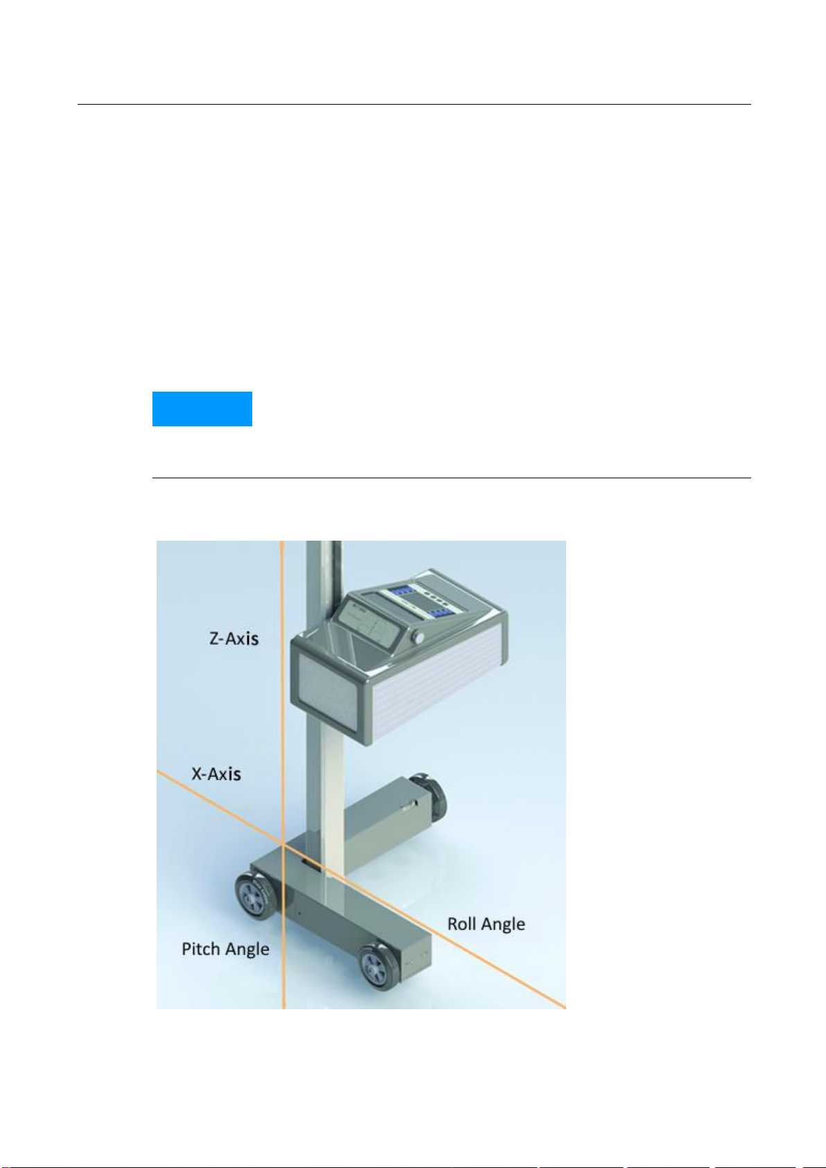
2.4 Electronic Levelling ................................................................................................................9
2.4.1 Compensation Coordinate Axes of MLT 3000 .......................................................................9
2.4.2 Angle Symbols......................................................................................................................10
2.5 Definition of Technical Terms..............................................................................................11
2.5.1 Pitch Angle ...........................................................................................................................11
2.5.2 Low Beam.............................................................................................................................11
2.5.3 High Beam............................................................................................................................12
3Operation .....................................................................................................................13
3.1 Switching On / Off................................................................................................................13
3.2 Aligning ................................................................................................................................14
3.2.1 Laser Alignment Unit (Option).............................................................................................14
3.2.2 LED Adjustment Aid (Option)...............................................................................................15
3.3 Light Selection Buttons........................................................................................................16
3.3.1 Headlight Test according to § 29 StVZO (Germany)............................................................16
3.3.2 Showing the Button Labels ..................................................................................................17
3.3.3 Adjusting the Pitch Angle.....................................................................................................17
3.3.4 Choosing the Vehicle Class ..................................................................................................18
3.3.5 Browsing back through the Test Screens.............................................................................18
3.3.6 Choosing between Left-Hand or Right Hand Traffic............................................................19
3.3.7 Manufacturer-Specific Test Instructions (OEM)..................................................................19
3.3.8 Navigating through the Test Levels .....................................................................................21
3.4 Testing the Headlights .........................................................................................................22

4
BA380701-en
3.4.1 Test Phase Indication via Light Buttons...............................................................................22
3.4.2 Measuring ............................................................................................................................22
3.4.3 Light Selection Buttons Disabled .........................................................................................23
3.4.4 Adjusting: Setting the Headlights in Real Time....................................................................24
3.4.5 Saving the Measurement Values to PDF .............................................................................25
3.5 Settings ................................................................................................................................27
3.5.1 Variables ..............................................................................................................................27
3.5.2 User Settings........................................................................................................................29
3.5.3 Language..............................................................................................................................30
3.5.4 Calibrating the Camera according to Directive....................................................................31
3.5.5 Country Specifications .........................................................................................................33
3.5.6 Settings with Password........................................................................................................34
3.5.7 List of Variables (Extract).....................................................................................................35
3.6 Interfaces and Software Updates ........................................................................................36
3.7 EUROSYSTEM v7.50 .............................................................................................................38
4Energy Management and Troubleshooting ...................................................................41
4.1 Charging the Battery............................................................................................................41
4.2 Battery Status ......................................................................................................................42
4.2.1 Battery Life...........................................................................................................................42
4.2.2 Energy Saving Function........................................................................................................42
4.2.3 Protection against Deep Discharge......................................................................................42
4.2.4 Protection against Mechanical Damage..............................................................................42
4.2.5 Data Recording for Error Analysis........................................................................................43
4.3 Troubleshooting...................................................................................................................44
5Maintenance.................................................................................................................44
5.1 Care Instructions..................................................................................................................44
5.2 Spare Parts...........................................................................................................................44
6Disposal ........................................................................................................................45
7Contents of the Declaration of Conformity ...................................................................45

5
BA380701-en
1Safety
1.1 Introduction
Thoroughly read this manual before operating the equipment and comply with the
instructions. Always display the manual in a conspicuous location.
Personal injury and property damage incurred due to non-compliance with these
safety instructions are not covered by the product liability regulations.
1.2 Symbols and Signal Words
1.2.1 Personal Injury
DANGER
indicates an immediate hazard which, if not avoided, will result in death or severe per-
sonal injury.
WARNING
indicates a potential hazard which, if not avoided, could result in death or severe per-
sonal injury.
CAUTION
indicates a potential hazard which, if not avoided, could result in moderate or minor
personal injury.
1.2.2 Property Damage
NOTICE
indicates a potentially harmful situation which, if not avoided, could result in damage
to the equipment or surrounding objects.
1.2.3 Information
indicates important information notes.

6
BA380701-en
1.3 Intended Use
This device only serves to check and adjust the alignment of vehicle headlights.
This device cannot be modified without the express, written consent of the
manufacturer. Any infringement renders the conformity declaration invalid.
1.4 Requirements on Operating and Service Personnel
WARNING
All persons employed in the operation, maintenance, installation, removal and disposal
of the device must
be at least 18 years old,
be mentally and physically suited for these activities,
be demonstrably trained and instructed in writing,
have read and understood the operating instructions, especially the instructions
what to do in the event of defects or malfunctions,
be on record as having been instructed in safety guidelines,
have practical experience in working with vehicle lifts and the hazards inherent in
such equipment.
1.5 Safety Instructions
NOTICE
This device must only ever be operated within its performance limits.
All parts of the electrical system must be protected against damp and humidity.
All service work must be performed by service technicians employed by the manu-
facturer or by authorized service partners.
Never expose the lens to direct sunlight. The bundling of light may cause fire dam-
age inside the housing.
Only ever clean the lens with a soft cloth and a glass cleaning agent.
CAUTION
Optional laser alignment unit: Never look into the laser beam (laser class 2M). Comply
with work safety and accident prevention directives (H&SW regulations) in respect of
laser radiation.

7
BA380701-en
2Description
2.1 Requirements for the Place of Installation
Please observe your national guidelines and specifications.
2.2 Technical Data
Measuring range
above hotspot
0…800 mm / 10 m (0…8 %)
above pitch angle
0…300 mm / 10 m (0…3 %)
below
0…700 mm / 10 m (0…7 %)
left
0…1000 mm / 10 m (0…10 %)
right
0…1000 mm / 10 m (0…10 %)
Light intensity
0…125 000 cd
Illuminance
0…200 lx
Measuring distance
100…500 mm
Adjustment path of lens centre above floor
240…1500 mm
Deviation of intensity
±5 %
Deviation from one axle
±5'
Compensation of ground unevenness
±3 %
Temperature
+5…+40 °C
Relative humidity
20…80 %
Supply voltage
100…240 V AC, 50/60 Hz
Charging voltage / Battery voltage
24 V DC / 12 V DC
Dimensions (W x H x D)
655 x 1770 x 720 mm
Net weight / Shipping weight
65 kg / 80 kg
Prototype release number
TPN100110935

8
BA380701-en
2.3 Design
A
Mirror, with optional
laser alignment unit
E
Charging socket
B
Column
F
Casing, with adjusting handle
C
Display
G
Carriage, with spirit level
D
USB port
H
Battery compartment
A
B
D
G
H
C
E
F

9
BA380701-en
2.4 Electronic Levelling
This headlight tester comes standard with an electronic position sensor which
determines the inclination angle of the device. The software compensates possible
deviations in the X- and Z-axes while calculating the position of the headlights.
The headlight tester may be set up on uneven surfaces even if the ground unevenness
is outside the permissible tolerances, provided that the maximum unevenness does
not exceed the headlight tester’s self-levelling capacity of 3%.
After enabling the respective function, the compensation values can be checked using
a dot or cross hair laser. See section “Operation > Settings > Calibrating the Camera
according to Directive”.
NOTICE
This function must be enabled exclusively by authorised service technicians and is ap-
plicable for the respective test surface only.
2.4.1 Compensation Coordinate Axes of MLT 3000

10
BA380701-en
2.4.2 Angle Symbols
Once the adjustment of the inclination sensor has been completed, an angle symbol
appears in the info bar to indicate the adjusted/active inclination axes.
Overview of symbols:
Both axes adjusted/active,
headlight tester ready for op-
eration
Z-axis active, headlight tester
ready for operation
Both axes active, inclination of
Z- and X-axis too large, no
measurement possible
Z-axis active, inclination too
large, no measurement possi-
ble
Both axes active, inclination of
X-axis too large, no measure-
ment possible
X-axis active, headlight tester
ready for operation
Both axes active, inclination of
Z-axis too large, no measure-
ment possible
X-axis active, inclination too
large, no measurement possi-
ble

11
BA380701-en
2.5 Definition of Technical Terms
2.5.1 Pitch Angle
Angle of inclination of light-dark limit against the test surface.
The inclination of headlight lighting bundle against the test surface is expressed as a
percentage, using 10 m as a reference parameter:
1000
hH
X 100
2.5.2 Low Beam

12
BA380701-en
A
Light-dark limit
Boundary for light distribution between ‘top dark’ and ‘bottom light’ for low-
beam lights.
B
Inflection point
Synonymous with the light-dark limit for asymmetric low-beam lighting. The
deviation of the inflection point is expressed in %. 10 meters is used as the ref-
erence dimension.
α
Yaw angle
Angle between the inflection point on the rising component of the light-dark
limit and the horizontal line for asymmetric low-beam light.
β
Rolling angle
Angle between the left component of the light-dark limit and the horizontal,
usually 0°.
2.5.3 High Beam
C
Central mark
From the central mark, the deviation of hot-spot is specified in X and Y direc-
tions.
D
Hot spot
Center of light beam for high-beam. The deviation of hot spot from central mark
is expressed in %.10 meters is used as the reference dimension.

13
BA380701-en
3Operation
3.1 Switching On / Off
The headlight tester is operated via touchscreen buttons. The resistive touchscreen
reacts to pressure and can also be operated while wearing work gloves.
The On/Off button is on the right-hand side underneath the touchscreen.
Press to confirm Switch Off.

14
BA380701-en
3.2 Aligning
When using guide rails, position the device centrally in front of the vehicle.
Without guide rails, the device must be adjusted in front of each headlight. Please ob-
serve your national guidelines and specifications.
The device is correctly aligned when two symmetrical reference points on the front of
the vehicle are located on the black line of the alignment mirror.
3.2.1 Laser Alignment Unit (Option)
The optional unit is integrated into the mirror holder. The device is correctly aligned
when the laser pointer is parallel to two symmetrical reference points on the front of
the vehicle.
Observe manufacturer’s instructions according to workshop manual.
CAUTION
Never look into the laser beam (laser class 2M). Comply with work safety and accident
prevention directives (H&SW regulations) in respect of laser radiation.
The AA Mignon batteries powering the laser are located in the alignment unit and can
be easily replaced.

15
BA380701-en
3.2.2 LED Adjustment Aid (Option)
This optional unit is integrated into the window housing (A) above the Fresnel lens.
The colour LEDs (B) pointing toward the vehicle indicate the direction of adjustment.
Green LED =
Optimum setting
(corresponds to green rating in the display centre)
Yellow LED =
Minor deviation within tolerance range
(corresponds to yellow direction arrows on the display)
Red LED =
Outside tolerance
(corresponds to red direction arrows on the display)
A
B

16
BA380701-en
3.3 Light Selection Buttons
3.3.1 Headlight Test according to § 29 StVZO (Germany)
Headlight test according to § 29 StVZO (Germany).
Use the OEM button for manufacturer-specific test instructions.

17
BA380701-en
3.3.2 Showing the Button Labels
When the Info button is activated, the button labels are shown instead of the symbols.
3.3.3 Adjusting the Pitch Angle
The pitch angle can be increased or reduced using the Arrow buttons.

18
BA380701-en
3.3.4 Choosing the Vehicle Class
The Truck/Car button activates the appropriate settings for the respective vehicle
class.
3.3.5 Browsing back through the Test Screens
Use the Back Arrow button to browse back through the test screens one by one.

19
BA380701-en
3.3.6 Choosing between Left-Hand or Right Hand Traffic
Left-hand/Right-hand traffic can be changed under “User Settings”. Right-hand traffic
is preset by default.
3.3.7 Manufacturer-Specific Test Instructions (OEM)
OEM area! Perform the test according to manufacturer’s instructions.

20
BA380701-en
Button “ALL“ makes several test levels available.
Example: testing Volkswagen matrix headlights
OEM area! Perform the test according to manufacturer’s instructions.
Table of contents
Other MAHA Test Equipment manuals

MAHA
MAHA MLT Series User manual

MAHA
MAHA TPS II User manual

MAHA
MAHA CONNECT Series User manual

MAHA
MAHA SA 2 Euro Manual

MAHA
MAHA MBT 2200 LON User manual

MAHA
MAHA MSD 3000 User manual

MAHA
MAHA MBT Series User manual

MAHA
MAHA MLT Series User manual

MAHA
MAHA MBT Series User manual

MAHA
MAHA MBT Series User manual