Makita EVH2000 User guide

ORIGINAL INSTRUCTION MANUAL
คู่มือการใช้งาน
BUKU PETUNJUK ASLI
SÁCH HƯỚNG DẪN SỬ DỤNG
Important:
Read this instruction manual carefully before putting the Power Sprayer into
operation and strictly observe the safety regulations! Preserve instruction
manual carefully!
ข้อสำคัญ:
โปรดอ่านคู่มือฉบับนี้อย่างละเอียดถี่ถ้วนก่อนเริ่มต้นการใช้งานเครื่องฉีดพ่นกำลังสูง
และปฏิบัติตามกฎข้อบังคับด้านความปลอดภัยอย่างเคร่งครัด! เก็บรักษาคู่มือฉบับนี้ไว้ในที่
ปลอดภัย!
Penting:
Bacalah buku petunjuk ini secara cermat sebelum memasang Semprotan
Bertenaga Mesin untuk digunakan dan perhatikan baik-baik peraturan-peraturan
keselamatan! Simpan buku petunjuk secara cermat.
LƯU Ý QUAN TRỌNG:
Hãy đọc kỹ sách hướng dẫn sử dụng này trước khi sử dụng Bình phun động
cơ và tuân thủ nghiêm ngặt những quy định về an toàn. Giữ gìn cẩn thận sách
hướng dẫn sử dụng này.
Power Sprayer
เครื่องฉีดพ่นกำลังสูง
Semprotan Bertenaga Mesin
BÌNH PHUN ĐỘNG CƠ
EVH2000

2
English
Thank you very much for purchasing a MAKITA POWER SPRAYER. We are pleased to offer you a
product that is the result of an extensive development program and many years of knowledge and
experience.
To safely obtain the best possible results from your MAKITA POWER SPRAYER, please read this
manual thoroughly before using the machine, and follow all instructions given herein to ensure
proper operation.
Table of Contents Page
Symbols............................................................................... 2
Safety instructions ............................................................... 3
Technical data...................................................................... 6
Designation of parts............................................................. 7
Assembly instructions.......................................................... 8
Before start of operation...................................................... 9
Mixing agricultural chemicals............................................. 11
Starting the engine ............................................................ 11
Stopping the engine........................................................... 13
Operation........................................................................... 14
Inspection and maintenance.............................................. 15
Troubleshooting................................................................. 18
SYMBOLS
It is very important to understand the following symbols when reading this instruction manual.
WARNING/DANGER
Read, Understand and Follow Instruction
Manual
Forbidden
No smoking
No Open Flame
Wear protective gloves
Keep the area of Operation
clear of all persons and pets
Wear eye protection, protective mask
and ear protection
Engine-manual Start
Emergency Stop
First Aid
ON/START
OFF/STOP
Fuel (Gasoline)
Recycling

3
SAFETY INSTRUCTIONS
General Instructions
– To ensure correct and safe operation, the user must read, understand and
follow this instruction manual to assure familiarity with the handling of the
power sprayer. Users insufciently informed will risk danger to themselves as
well as others due to improper handling.
–It is recommended only to loan the power sprayer to people who have proven
to be experienced with power sprayers.
–Always hand over the instruction manual.
– First-time users should ask the dealer for basic instructions to familiarize
oneself with the handling of a power sprayer.
–Children and young persons aged under 18 years must not be allowed to
operate the power sprayer. Persons over the age of 16 years may however
use the tool for the purpose of being trained only while under the direct
supervision of a qualied trainer.
–Use power sprayer with the utmost care and attention.
– Operate the power sprayer only if you are in good physical condition.
– Perform all work conscientiously and carefully. The user has to accept
responsibility for others.
– Never use the power sprayer while under the inuence of alcohol or drugs.
– Do not use the unit when you are tired.
– Save these instructions for future referral.
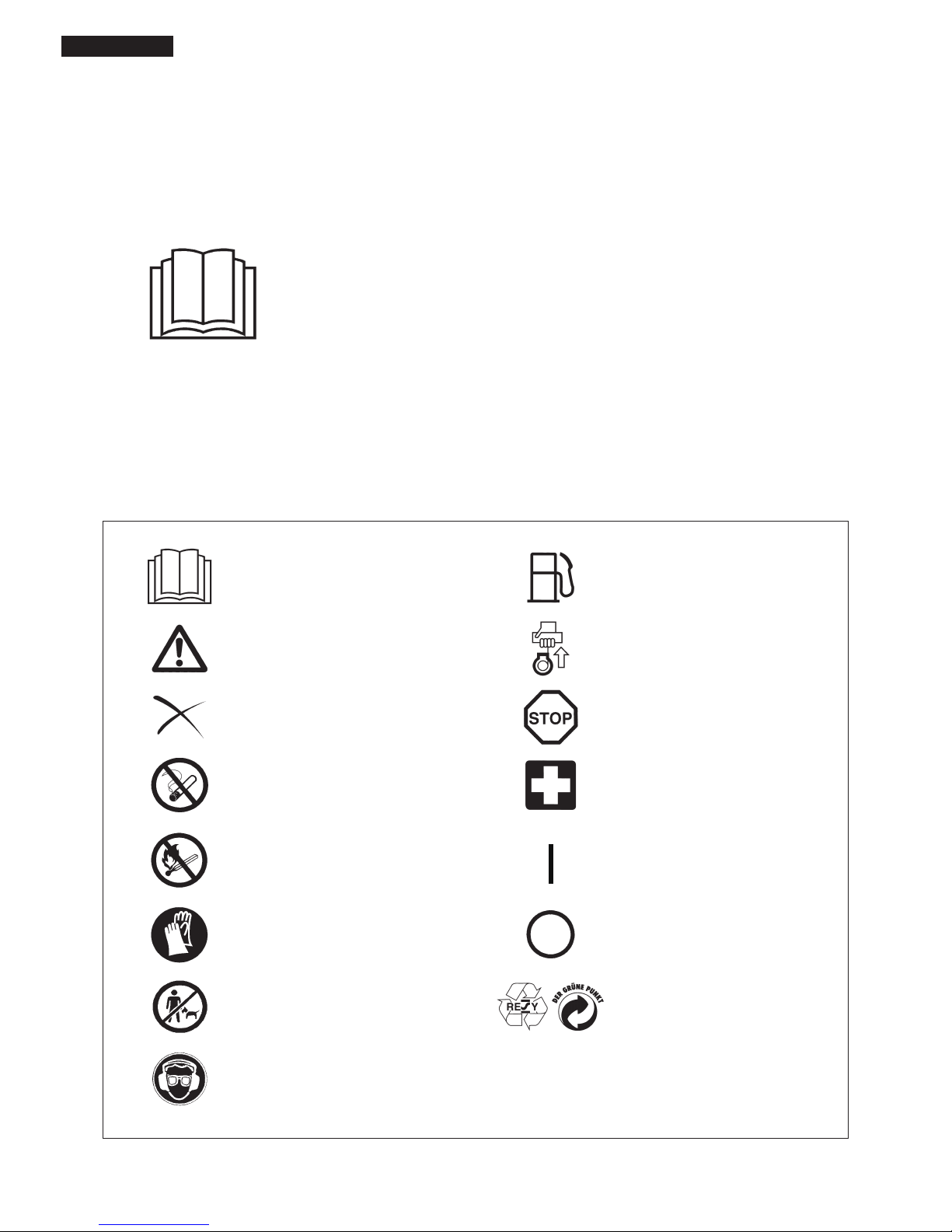
Personal protective equipment
– The clothing worn should be functional and appropriate, i. e. It should be tight-
tting but not cause a hindrance. Do not wear jewelry, clothing or long hair
which could be drawn into the air intake.
– In order to avoid head-, eye-, hand- or foot injuries as well as to protect you
hearing the following protective equipment and protective clothing must be
used during operation of the power sprayer.
Pay particular attention to the following regulations
– Please wear clothing that is functional and tight-tting, without restricting
movement when operating the power sprayer. Do not wear clothing or jewelry
that could get tangled with foliage or the machine.
– For adequate protection against head, eye, feet, hand, and hearing injuries,
the following protective equipment and clothing must be used when working
with the power sprayer.
1.Always wear adequate face protection (mask, protective goggles, etc.) to
protect the face, eyes and lungs from dust and chemicals.
2.To avoid hearing damage, wear adequate hearing protection at all times.
3.To protect skin from dust and chemicals, wear work clothes with long
sleeves and long pants at all times.
4.Always wear rubber gloves when operating or servicing the power sprayer.
5.When using the power sprayer, always wear sturdy shoes with non-slip
soles. Special work shoes are available to ensure good footing and protect
against injury.
–Always secure loose clothing, hair, and accessories such as towels etc.
Loose objects may become tangled in moving parts of the machine and
cause serious injury.
Starting up the Power Sprayer
– Please make sure that there are no children or other people within a working
range of 15 meters, also pay attention to any animals in the working vicinity.
Never use the power sprayer in urban areas.
–Before operating, always check that the power sprayer is safe for operation:
Check the security of the throttle lever. The throttle lever should be checked
for smooth and easy action. Check for clean and dry throttle lever and test
the function of the I - O switch.
360˚
15 meters
Waterproof cap
Protective
goggles
Long sleeves
Rubber
gloves
Work shoes
Long pants
Protective
mask
Ear protection

4
– Before starting the power sprayer, always make sure that the machine is in
safe operational condition and check whether the throttle lever is functioning
properly.
–Always check for and remove tools used during assembly of the machine.
Attached tools may be ung from the engine when it is started, causing
serious injury.
–Make sure that the power sprayer is clean and dry and test the STOP switch
to ensure that it is functioning properly.
–Stop the engine immediately if experiencing engine problems.
– When operating the power sprayer, take extra care not to inhale exhaust
fumes.
– Exhaust fumes are poisonous. Never operate the machine in an enclosed
room or an area with insufcient ventilation (risk of suffocation and gas
poisoning).
–Do not operate the power sprayer continuously for longer than one hour, and
observe a rest time of at least 30 minutes between each working hour.
–Stop the engine when resting or when the power sprayer is left unattended.
To protect other people and the power sprayer from damage, place the
machine in a safe location and make sure that no combustible material is
nearby. Never place a hot power sprayer onto dry grass or combustible
material. Placing the machine on dry grass or near combustible material is
extremely dangerous and may result in a re.
– Never operate the engine if the mufer is malfunctioning.
– Always turn off the engine before moving the power sprayer to a new location.
– Wait until the engine has cooled down, empty the fuel tank, and securely
attach the power sprayer before transporting the machine in a vehicle.
–Make sure that the fuel tank is completely empty and dry before shipping the
power sprayer.
Refueling
– Shut off the engine during refuelling, keep well away from open ame and do
not smoke.
–Avoid skin contact with petroleum products. Do not inhale fuel vapor. Always
wear protective gloves during refuelling. Change and clean protective
clothing at regular intervals.
–Take care not to spill either fuel or oil in order to prevent soil contamination
(environmental protection). Clean the power sprayer immediately after fuel
has been spilt. Allow wet cloths to dry before disposing in proper, covered
container to prevent spontaneous combustion.
–Avoid any fuel contact with your clothing. Change your clothing immediately
if fuel has been spilled on it (danger hazard).
–Inspect the fuel cap at regular intervals making sure that it stays securely
fastened.
–Carefully tighten the locking screw of the fuel tank. Change locations to start
the engine (at least 3 meters away from the place of refuelling).
–Never refuels in closed rooms. Fuel vapors accumulate at ground level (risk
of explosions).
–Only transport and store fuel in approved containers. Make sure stored fuel
is not accessible to children.
–Do not attempt to refuel a hot or a running engine.
Method of operation
– Only use the power sprayer in good light and visibility conditions. Never use
the power sprayer at night. Do not use the power sprayer during rainfall or
immediately after rain (danger of injury through slipping and falling in wet
conditions).
–Beware of slippery and wet areas (ice and snow) as there is a danger of
slipping, and always ensure secure footing.
–Never use the power sprayer while standing on a ladder.
– Never climb a tree to use the power sprayer from the tree.
– Never use the power sprayer while standing on an unstable surface.
– Do not point the nozzle of the power sprayer towards people or animals.
Flying debris may cause serious injury.
–Do not touch the spark plug connector while the engine is running.
– Do not touch moving parts of the power sprayer while the engine is running.
– Do not touch the mufer or other engine parts during operation or for a period
after the engine has stopped. These engine parts are extremely hot and may
cause serious burns.
• Resting
• Transport
• Refuelling
• Maintenance
• Tool replacement
3 meters

5
– Ensure that the toxicity of the pesticides or herbicides to be used is known
before use, and carefully read related use instructions to familiarize yourself
with the proper procedures for using the chemicals in question. If pesticides/
herbicides come in contact with your skin, immediately rinse the affected area
and thoroughly wash with soap. Firmly tighten the cap of the sprayer tank in
order to avoid chemical leaks.
Maintenance instructions
– Be kind to the environment. Operate the power sprayer with as little noise
and pollution as possible. In particular check the correct adjustment of the
carburetor.
–Clean the power sprayer at regular intervals and check that all screws and
nuts are securely tightened.
– Never service or store the power sprayer in the vicinity of open ames,
sparks, etc.
–Always store the power sprayer in a well-ventilated locked room and with an
emptied fuel tank.
Observe and follow all relevant accident prevention instructions issued by
the trade associations and by insurance companies. Do not perform any
modications to the power sprayer as this will risk your safety.
The performance of maintenance or repair work by the user is limited to those
activities as described in this instruction manual. All other work is to be done by
Authorized Service Agents.
Use only genuine spare parts and accessories supplied by MAKITA.
Use of non-approved accessories and tools means increased risk of accidents
and injuries. MAKITA will not accept any liability for accidents or damage
caused by the use of any non-approved attachment or accessories.
First aid
In case of accident make sure that a well-stocked rst-aid kit, is available in the
vicinity of the operations. Immediately replace any item taken from the rst aid
kit.
When asking for help, please give the following
information:
– Place of accident
– What happened
– Number of injured persons
– Extent of injuries
– Your name
Packaging
– The MAKITA power sprayer is delivered in a protective cardboard box to
prevent shipping damage. Cardboard is a basic raw material and is therefore
consequently reusable or suitable for recycling (waste paper recycling).

6
TECHNICAL DATA
Model EVH2000
Dimensions: (length x width x height) mm 380 x 420 x 635
Dry weight kg 9.1
Chemical tank capacity L 20
Pump
Type Horizontal opposed twin pistons
Max. Pressure MPa 2.5
Suction L 7.1
Engine
Model EH025A
Displacement cm324.5
Fuel Automobile gasoline
Fuel tank capacity L 0.5
Engine oil SAE 10-W-30 oil API SF or later (4-stroke automobile engine oil)
Engine oil capacity L 0.08
Caburetor type WALBRO WYL
Ignition system type Solid state ignition
Spark plag type NGK CMR6A (C type)
Electrode gap mm 0.7 - 0.8
Note: 1. Use the oil and spark plug specied by MAKITA.
2. This specication is subject to change without prior notice.

7
DESIGNATION OF PARTS
No. DESIGNATION OF PARTS No. DESIGNATION OF PARTS No. DESIGNATION OF PARTS
1 I-O Switch 9 Mufer 17 Quick connector
2 Throttle lever 10 Oil gauge 18 Handgrip
3 Choke lever 11 Primer Pump 19 Nozzle lever
4 Air cleaner cover 12 Chemical tank drain cap 20 Nozzle pipe
5 Plug cover 13 Chemical tank cap 21 Nozzle pipe holder
6 Starter knob 14 Chemical tank 22 Nozzle (wide angle twin head)
7 Fuel tank 15 Pressure dial 23
8 Fuel tank cap 16 Sprayer hose 24

8
ASSEMBLY INSTRUCTIONS
CAUTION: Before performing any work on the power sprayer, always switch off the motor and pull the spark plug connectors off the spark plug.
Always wear protective gloves!
CAUTION: Start the power sprayer only after having assembled it completely.
1. ASSEMBLY OF NOZZLE
Refer to the gure on the previous page (DESIGNATION OF PARTS) to assemble handgrip, nozzle lever, nozzle pipe and nozzle. Be careful to
put parts together properly to prevent leaks.
2. SETTING OF SHOULDER HARNESS
Set the two shoulder harnesses on a chemical tank in a way shown below without any twists of the shoulder harnesses. Instructions are given
about the ones for one of the shoulder harnesses.
Setting upper part of shoulder harness
Chemical tank
Upper buckle
①② ③ Pull the harness in the direction of
the arrow and put its folded end at
the lower end of the buckle.
Setting lower part of shoulder harness
Upper buckle
Lower buckle
① ②
③
Chemical tank
Put the back harnesses 'A'. one of the two
overlapped harnesses, at the metallic hook in
a way shown below at ②and ③.
Put the part 'A', of the harness through
this gap of the metallic hook.
Then raise the harness to
the degree of 90, in the
direction of the arrow.
Metallic hook
Repeat the same instructions for the
other shoulder harness to nish the
setting.
Metallic hook

9
BEFORE START OF OPERATION
Inspection and Rell of Engine Oil
– Perform the following procedure, with the engine cooled down.
– While keeping the engine level, remove the oil gauge, and conrm that the oil is lled within the upper and lower limit marks.
When the oil is in short in such a way that the oil gauge touches the oil only by its tip, in particular with the oil gauge remaining inserted in the
crankcase without screwing-in (Fig. 1), rell new oil near the port (Fig. 2).
– For reference, the oil rell time is about 10h (10 times or 10 tanks of oil rell).
– If the oil changes in color or mixes with dirt, replace it with new one. (For the interval and method of replacement, refer to P 15)
Recommended oil: SAE 10W-30 oil of API Classication, Class SF or higher (4-stroke engine for automobile)
Oil volume: Approx. 0.08 L
Note: If the engine is not kept upright, oil may go into around the engine, and may be relled excessively.
If the oil is lled above the limit, the oil may be contaminated or may catch re with white.
Point 1 in Replacement of Oil “Oil Gauge”
– Remove dust or dirt near the oil rell port, and detach the oil gauge.
– Keep the detached oil gauge free of sand or dust. Otherwise, any sand or dust adhering to the oil gauge may cause irregular oil circulation
or wear on the engine parts, which will result in troubles.
–As an example to keep the oil gauge clean, it is recommended to insert the oil gauge on its knob side into the engine cover, as shown in
Fig.3.
If oil adheres around
this tip, rell new oil.
Fig.1 Fig.2
Upper limit
(Edge of oil rell port)
Fig.3
Oil gauge

10
1) Keep the engine level, and detach the oil gauge.
2) Fill oil up to the edge of the oil rell port. (Refer to Fig.2 of the preceding
page).
Feed oil with the lubricant rell container.
3) Securely tighten the oil gauge. Insufcient tightening may cause oil leakage.
Fuel tank cap
Fuel upper limit
Fuel tank
Point 2 in Replacement of Oil: “If oil spills out”
–If oil spills out between the fuel tank and engine main unit, the oil is sucked into through the cooling air intake port, which will contaminate
the engine. Be sure to wipe out spilt oil before start of operation.
REFUELING
Handling of Fuel
It is necessary to handle fuel with utmost care. Fuel may contain substances similar to solvents. Refueling must be performed in a sufciently
ventilated room or in the open air. Never inhale fuel vapor, and keep fuel away from you. If you touch fuel repeatedly or for a long time, the skin
becomes dry, which may cause skin disease or allergy. If fuel enters into the eye, clean the eye with fresh water. If your eye remains still irritated,
consult your doctor.
Storage Period of Fuel
Fuel should be used up within a period of 4 weeks, even if it is kept in a special container in a well-ventilated shade.
If a special container is not used or if the container is not covered, fuel may deteriorate in one day.
STORAGE OF MACHINE AND REFILL TANK
–Keep the machine and tank at a cool place free from direct sunshine.
– Never keep the fuel in the cabin or trunk.
Fuel
The engine is a four-stroke engine. Be sure to use an automobile gasoline (regular gasoline or premium gasoline).
Points for Fuel
–Never use a gasoline mixture which contains engine oil. Otherwise, it will cause excessive carbon accumulation or mechanical troubles.
– Use of deteriorated oil will cause irregular startup.
Refueling
WARNING: INFLAMMABLES STRICTLY PROHIBITED
Gasoline used: Automobile gasoline (unleaded gasoline)
– Loosen the tank cap a little so that there will be no difference in atmospheric
pressure.
– Detach the tank cap, and refuel, discharging air by tilting the fuel tank so
that the refuel port will be oriented upward. (Never rell fuel full to the oil rell
port.)
–Wipe well the periphery of the tank cap to prevent foreign matter from
entering into the fuel tank.
–After refueling, securely tighten the tank cap.
• If there is any aw or damage on the tank cap, replace it.
• The tank cap is consumable, and therefore should be renewed every two to
three years.

11
1) Mixing agricultural chemicals
1. Agricultural chemicals are toxic. When working with agricultural chemicals, strictly follow the instructions provided by the manufacturer at
all times.
2. Always use the provided strainer when pouring agricultural chemicals into the chemical tank.
3. Firmly tighten the chemical tank cap to prevent leaks.
4. If chemicals are to be mixed inside the chemical tank, always add water before other agricultural chemicals.
CAUTION:
• Always handle agricultural chemicals with the utmost care. Should your skin come into contact with agricultural chemicals by accident,
immediately rinse the affected area with large amounts of water.
2) Using a different type of chemical agent
1. Take extra care to thoroughly rinse the sprayer tank, pump and nozzle before adding different chemical agents to the sprayer tank. Mixing
the residues of previously used agricultural chemicals with other chemical agents may cause toxin-induced diseases.
CAUTION:
• Never spray chemicals undiluted.
• See the following chart for ratio information that is useful when diluting chemicals.
Chemical
Water
Dilution ratio
500 1,000 2,000
4L 8mL 4mL 2mL
6L 12mL 6mL 3mL
8L 16mL 8mL 4mL
10L 20mL 10mL 5mL
12L 24mL 12mL 6mL
15L 30mL 15mL 7.5mL
20L 40mL 20mL 10mL
MIXING AGRICULTURAL CHEMICALS
WARNING
• Never attempt engine start in a place where the fuel has been supplied. When starting the engine, keep a distance of at least 3m.
- Otherwise, it will may cause ignition or re.
•Exhaust gas from the engine has toxic consequences. Do not operate the engine in a poorly-ventilated place. Such as in a tunnel,
building, etc.
-Operating the engine in the poorly-ventilated place may cause poisoning by exhaust gas.
•In case of derection of any abnormality sound, odor, vibration after start, stop the engine immediately and carry out inspection.
- If the engine is operated without attending such abnomality, an accident may occur.
• Conrm that the engine stops when the stop switch is set to “O” position.
STARTING THE ENGINE

12
1) Before starting the engine, always conrm that the chemical tank contains
uid.
2) Turn the nozzle lever to the CLOSED position.
3) Rotate the pressure dial and align the STARTING tab with the mark.
1) When the engine is cold, or when the fuel it refueled
(1) Set this machine on a at space.
(2) Set the I-O switch to “ I “ position.
(3) Make sure that the throttle lever is the SLOW position.
(4) Continue to push the primer pump untill fuel enters into the primer pump.
• In general, fuel enters into the carburetor by 7 to 10 Pushes.
• If the primer pump is pushed excessively, an excess of gasoline returns to
the fuel tank.
(5) Lifting the choke lever of the air cleaner right side, close the choke lever.
“STARTING” TAB
PRESSURE DIAL
SLOW
Throttle lever switch
(ON)
Primer pump
Close
NOZZLE LEVER
CLOSED

13
(6) Hold the element cover with a left hand to prevent the engine from moving,
settle down to take the stable position.
(7) Pull out slowly the starter handle till a certain resistance is felt. Return the
starter handle backward once from this position, then pull it out with force.
•Never pull the rope to the full.
• Once the start knob is pulled, never release your hand immediately. Hold
the start knob until it returns to its original point.
(8) When the engine starts, open the choke lever.
• Open the choke lever progressively while checking the engine operation.
Be sure to open the choke lever to the full in the end.
•In cold or when the engine is cooled down, never open the choke lever
suddenly. Otherwise, the engine may stop.
(9) Continue warm-up operation for 2 to 3 minutes.
(10) Rotation of the engine speed stabilizes and when from low speed making
at high speed rotation, if reaches the point where it accelerates smoothly,
it is completion of warming-up.
NOZZLE LEVER
CLOSED
SLOW
Throttle lever I-O switch
O (OFF)
Open
2) When the engine is warm
(1) Place the engine on a at ground.
(2) Press the primary pump several times.
(3) Conrm that the choke lever is open.
(4) Hold the element cover with a left hand to prevent the engine from moving, settle down to take the stable position.
(5) Pull out slowly the starter handle till a certain resistance is felt. Return the starter handle backward once from this position, then pull it out
with force.
(6) When the engine is difcult to start, open the throttle valve by about 1/3.
STOPPING THE ENGINE
1) Turn the nozzle lever to the CLOSE position.
2) Turn the I-O switch to “O” Position.
3) Move the throttle lever to the SLOW position.

14
1. Start the engine (see page 11)
2. After starting the engine, mount the power sprayer on your back and adjust the shoulder straps so as to keep the unit as close to your body
as possible. Put the engine in idle and take care not to tilt the power sprayer unit too much.
OPERATION
Adjust straps as follows.
1) Loosening straps:
①Raise buckle
② Pull on the end of the strap attached to the power
sprayer.
2) Tightening straps:
③Pull on the free end of the strap.
Note: If straps do not carry any weight, they can be tightened with relative
ease.
3. Select the desired opereting position the pressure dial.
4. Move the throttle lever at the desired position with the nozzle lever moved
while observing the spray.
CAUTION
When using the power sprayer always spray downwind. Take special care to avoid situations where sprayed chemicals are blown back
towards you.
Buckle
Tighten
Loosen
HIGH PRESSURE
LOW PRESSURE
PRESSURE DIAL
SLOW
Throttle lever
FAST
NOZZLE LEVER
CLOSED
OPEN

15
INSPECTION AND MAINTENANCE
1. Replacement of engine oil
Deteriorated engine oil will shorten the life of the sliding and rotating parts to a great extent. Be sure to check the period and quantity of
replacement.
DANGER
• Before inspection and maintenance, stop the engine and allow it to cool. Remove also the spark plug and plug cap.
- If inspection or maintenance is attempted immediately after engine stop or with the plug cap left attached, the operator may suffer burn
or an accident due to careless startup.
• After inspection and maintenance, be sure to conrm that all parts are assembled. Then, proceed to operation.
DANGER
• In general, the engine main unit and engine oil still remain hot just after the engine is stopped. In replacement of oil, conrm that the
engine main unit and engine oil are sufciently cooled down. Otherwise, there may remain a risk of scald. In addition just after of the
engine stopping because oil does not nish to return in the oil case, becomes cause of the oil inserting too much
• If the oil lled above the limit, it may be contaminated or may catch re with white smoke.
Interval of replacement: Initially, every 20 operating hours, and subsequently every 50 operating hours
Recommended oil: SAE10W-30 oil of API Classication SF Class or higher (4-stroke engine oil for automobile)
In replacement, perform the following procedure.
1) Conrm that the tank cap is tightened securely.
2) Detach the oil gauge.
- Keep the oil gauge free from dust or dirt.
3) Use the provided oil extraction bottle to remove the old oil from the oil
reservoir.
•Squeeze the body of the bottle to and insert the nozzle into the oil.
Release pressure on the bottle to draw the old oil from the oil reservoir.
•When the oil reservoir is almost empty, tilt the power sprayer unit slightly
in order to facilitate removal of the remaining engine oil.
4) Return the engine to level. Using the lubricant rell bottle, ll with new oil up
to the top of the oil reservoir.
5) Replace and securely tighten the dip stick. Insufcient tightening will lead to
oil leaks.
• Use the provided oil extraction bottle and lubricant rell bottle for their
intended purposes.
Fuel tank cap
Oil gauge
Oil extraction bottle Lubricant rell bottle

16
Points in replacement of engine oil
• Never discard replaced engine oil in garbage, earth or sewage ditch. Disposal of oil is regulated by law. In disposal, always follow the
relevant laws and regulations. For any points remaining unknown, contact Authorized Service Agent.
•Oil will deteriorate even when it is kept unused. Perform inspection and replacement at regular intervals (replace with new oil every 6
months).
2. Cleaning of air cleaner
WARNING: INFLAMMABLES STRICTLY PROHIBITED
Interval of Cleaning and Inspection: Daily (every 10 operating hours)
– Remove the air cleaner cover-xing bolts.
– Pull the lower side of the cover and detach the air cleaner cover.
– Fully close the choke, and ensure that the carburetor is free from dust or dirt.
– Remove the air cleaner element, wash element with neutral detergent diluted
with tepid water, and let element dry. Replace the element in the position
indicated by the dotted line in g. 1.
–Use a piece of paper to wipe off any oil adhering to the air cleaner cover and
plate breather.
–Immediately after cleaning, attach the cleaner cover and use the attachment
bolt for xing. (When remounting, position the upper part of the cover rst and
then the lower.).
3. Checking the spark plug
– Only use the supplied universal wrench to remove or to install the spark plug.
– The gap between the two electrodes of the spark plug should be 0.7-0.8 mm
(0.028”-0.032”). If the gap is too wide or too narrow, adjust it. If the spark
plug is clogged with carton or fouled, clean it thoroughly or replace it.
CAUTION: Never touch the spark plug connector while the engine is running
(danger of high voltage electric shock).
4. Cleaning of fuel lter
WARNING: INFLAMMABLES STRICTLY PROHIBITED
Interval of Cleaning and Inspection: Monthly (every 50 operating hours)
Suction head in the fuel tank
– The fuel ller (1) of the suction head is used to ller the fuel required by the
carburetor.
– A periodical visual inspection of the fuel lter is to be conducted. For that
purpose open the tank cap, use a wire hook and pull out the suction head
through the tank opening. Filters found to have hardened, been polluted or
clogged up are to be replaced.
– Insufcient fuel supply can result in the admissible maximum speed being
exceeded. It is therefore important to replace the fuel lter at least quarterly
to ensure satisfactory fuel supply to the carburetor.
Place cut part in
this position (top left) Element Air cleaner cover
Plate
Breather section
Attachment
bolt
Line (slashed line)
Fig.1 Element (dotted line)
0.7~0.8 mm
(0.028”-0.032”)
Fuel pipe
Hose clamp
Fuel
lter (1)

17
Fault location
Fault System Observation Cause
Engine not starting or with
difculty
Ignition system Ignition spark O.K. Fault in fuel supply or compression system, mechanical
defect
No ignition spark STOP-switch operated, wiring fault or short circuit, spark
plug or connector defective, ignition module faulty
Fuel supply Fuel tank lled Incorrect choke position, carburetor defective, fuel supply
line bent or blocked, fuel dirty.
Compression No compression when
pulled over
Cylinder bottom gasket defective, crankshaft seals
damaged, cylinder or piston rings defective or improper
sealing of spark plug
Mechanical fault Starter not engaging Broken starter spring, broken parts inside of the engine
Warm start problems Tank lled ignition spark
existing
Carburetor contaminated, have it cleaned
Engine starts but dies Fuel supply Tank lled Incorrect idling adjustment, carburetor contaminated
Fuel tank vent defective, fuel supply line interrupted,
cable or STOP-switch faulty
Insufcient performance Several systems may
simultaneously be
affected
Engine idling poor Air lter contaminated, carburetor contaminated, mufer
clogged, exhaust duct in the cylinder clogged
Operating time
Item
Before
operation
After
lubrication
Daily
(10h) 30h 50h 200h
Shutdown
/rest
Engine oil
Inspect/clean
Replace *1
Tightening parts
(bolt, nut) Inspect
Fuel tank
Clean/inspect
Drain fuel *3
Throttle lever Check function
Stop switch Check function
Low-speed rotation Inspect/adjust
Air cleaner Clean
Ignition plug Inspect
Cooling air duct Clean/inspect
Fuel pipe
Inspect
Replace *2
Fuel lter Clean/replace
Clearance between air intake
valve and air discharge valve Adjust *2
Oil tube Inspect *2
Engine overhaul *2
Carburetor Drain fuel *3
*1 Perform initial replacement after 20h operation.
*2 For the 200 operating hour inspection, request Authorized Service Agent or a machine shop.
*3 After emptying the fuel tank, continue to run the engine and drain fuel in the carburetor.

18
TROUBLESHOOTING
– Before making a request for repairs, check a trouble for yourself. If any abnormality is found, control your machine according to the description
of this manual. Never tamper or dismount any part contrary to the description. For repairs, contact Authorized Service Agent or local
dealership.
State of abnormality Probable cause (malfunction) Remedy
Engine does not start
Failure to operate primer pump Push 7 to 10 times.
Low pulling speed of starter rope Pull strongly.
Lack of fuel Feed fuel.
Clogged fuel lter Clean
Broken fuel tube Straighten fuel tube
Deteriorated fuel Deteriorated fuel makes starting more difcult.
Replace with new one. (Recommended
replacement: 1 month)
Excessive suction of fuel Set throttle lever from medium speed to high
speed, and pull starter handle until engine
starts.
If engine will not start still, remove spark plug,
make electrode dry, and reassemble them as
they originally are. Then, start as specied.
Detached plug cap Attach securely
Contaminated spark plug Clean
Abnormal clearance of spark plug Adjust clearance
Other abnormality of spark plug Replace
Abnormal carburetor Make request for inspection and maintenance.
Starter rope cannot be pulled Make request for inspection and maintenance
Abnormal drive system Make request for inspection and maintenance
Engine stops soon
Engine speed does not increase
Insufcient warm-up Perform warm-up operation
Choke lever is set to “CLOSE” although
engine is warmed up Set to “OPEN”
Clogged fuel lter Clean
Contaminated or clogged air cleaner Clean
Abnormal carburetor Make request for inspection and maintenance
Abnormal drive system Make request for inspection and maintenance
Detached throttle wire Attach securely
Engine does not stop.
Run engine at idling, and set choke
lever to CLOSE.
Detached connector Attach securely
Abnormal electric system Make request for inspection and maintenance.
When the engine does not start after warm-up operation:
If there is no abnormality found for the check items, open the throttle by about 1/3 and start the engine.

19

20
Table of contents
Languages:
Other Makita Paint Sprayer manuals

Makita
Makita BVF154 User manual

Makita
Makita DUS054Z User manual

Makita
Makita DVF104 User manual

Makita
Makita BVF154 User manual

Makita
Makita DUS054 User manual

Makita
Makita DUS108 User manual

Makita
Makita US053D User manual

Makita
Makita EF1550RH User manual

Makita
Makita PM7651H User guide

Makita
Makita BVF104 User manual

Makita
Makita US053D User manual

Makita
Makita BVF104 User manual

Makita
Makita EVH2000 User guide

Makita
Makita EVH2000 User guide

Makita
Makita EVH2000 User manual

Makita
Makita DVF104 User manual

Makita
Makita DVF104 User manual

Makita
Makita BVF104 Manual

Makita
Makita DUS108 User manual

Makita
Makita XSU03 User manual