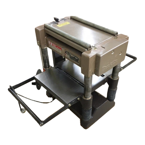
Makita 2012NB User manual

1
ENGLISH (Original instructions)
INSTRUCTION MANUAL
DOUBLE INSULATION
IMPORTANT: Read Before Using.
Thicknesser
2012NB
004461

2
ENGLISH (Original instructions)
SPECIFICATIONS
Model 2012NB
Cutting width 304 mm
3.0 mm of stock width less than 150 mm
1.5 mm of stock width from 150 mm to 240 mm
Max. cutting depth
1.0 mm of stock width from 240 mm to 304 mm
Feed rate (min-1) 8.5 m
Table size (W x L) 304 mm x 771 mm
No load speed (min-1) 8,500
Overall length (W x L x H) 483 mm x 771 mm x 401 mm
Net weight 28.1 kg
safety class /II
• Due to our continuing programme of research and development, the specifications herein are subject to change without notice.
• Specifications may differ from country to country.
• Weight according to EPTA-Procedure 01/2003
END201-5
Symbols
The following show the symbols used for the equipment.
Be sure that you understand their meaning before use.
・Read instruction manual.
・DOUBLE INSULATION
・Only for EU countries
Do not dispose of electric equipment
together with household waste material!
In observance of European Directive
2002/96/EC on waste electric and
electronic equipment and its
implementation in accordance with
national law, electric equipment that
have reached the end of their life must
be collected separately and returned to
an environmentally compatible recycling
facility.
ENE001-1
Intended use
The tool is intended for planing wood.
ENF002-1
Power supply
The tool should be connected only to a power supply of
the same voltage as indicated on the nameplate, and can
only be operated on single-phase AC supply. They are
double-insulated in accordance with European Standard
and can, therefore, also be used from sockets without
earth wire.
ENF100-1
For public low-voltage distribution systems of
between 220 V and 250 V.
Switching operations of electric apparatus cause voltage
fluctuations. The operation of this device under
unfavorable mains conditions can have adverse effects
to the operation of other equipment. With a mains
impedance equal or less than 0.38 Ohms it can be
presumed that there will be no negative effects. The
mains socket used for this device must be protected with
a fuse or protective circuit breaker having slow tripping
characteristics.
ENG905-1
Noise
The typical A-weighted noise level determined according
to EN61029:
Sound pressure level (LpA) : 86 dB(A)
Sound power level (LWA) : 99 dB(A)
Uncertainty (K) : 3 dB(A)
Wear ear protection
ENH037-1
For European countries only
EC Declaration of Conformity
We Makita Corporation as the responsible
manufacturer declare that the following Makita
machine(s):
Designation of Machine:
Thicknesser
Model No./ Type: 2012NB
are of series production and
Conforms to the following European Directives:
2006/42/EC
And are manufactured in accordance with the following
standard or standardized documents:
EN12100-1, IEC61029, EN860
The EC Type-Examination Certificate No.
10-SKM-CM-0523

3
The EC Type-Examination per 2006/42/EC was
performed by:
Inspecta Sweden AB
PO Box 30100
SE-104 25 STOCKHOLM, Sweden
Identification No. 0409
The technical documentation is kept by our authorized
representative in Europe who is:
Makita International Europe Ltd,
Michigan, Drive, Tongwell,
Milton Keynes, MK15 8JD, England
3.3.2010
000230
Tomoyasu Kato
Director
Makita Corporation
3-11-8, Sumiyoshi-cho,
Anjo, Aichi, JAPAN
ENA001-2
SAFETY INSTRUCTIONS
WARNING! When using electric tools, basic safety
precautions, including the following, should always
be followed to reduce the risk of fire, electric shock
and personal injury. Read all these instructions
before operating this product and save these
instructions.
For safe operations:
1. Keep work area clean.
Cluttered areas and benches invite injuries.
2. Consider work area environment.
Do not expose power tools to rain. Do not use
power tools in damp or wet locations. Keep work
area well lit. Do not use power tools where there is
risk to cause fire or explosion.
3. Guard against electric shock.
Avoid body contact with earthed or grounded
surfaces (e.g. pipes, radiators, ranges,
refrigerators).
4. Keep children away.
Do not let visitors touch the tool or extension cord.
All visitors should be kept away from work area.
5. Store idle tools.
When not in use, tools should be stored in a dry,
high or locked up place, out of reach of children.
6. Do not force the tool.
It will do the job better and safer at the rate for
which it was intended.
7. Use the right tool.
Do not force small tools or attachments to do the
job of a heavy duty tool. Do not use tools for
purposes not intended; for example, do not use
circular saws to cut tree limbs or logs.
8. Dress properly.
Do not wear loose clothing or jewellery, they can
be caught in moving parts. Rubber gloves and
non-skid footwear are recommended when
working outdoors. Wear protecting hair covering to
contain long hair.
9. Use safety glasses and hearing protection.
Also use face or dust mask if the cutting operation
is dusty.
10. Connect dust extraction equipment.
If devices are provided for the connection of dust
extraction and collection facilities ensure these are
connected and properly used.
11. Do not abuse the cord.
Never carry the tool by the cord or yank it to
disconnect it from the socket. Keep the cord away
from heat, oil and sharp edges.
12. Secure work.
Use clamps or a vice to hold the work. It is safer
than using your hand and it frees both hands to
operate the tool.
13. Do not overreach.
Keep proper footing and balance at all times.
14. Maintain tools with care.
Keep cutting tools sharp and clean for better and
safer performance. Follow instructions for
lubrication and changing accessories. Inspect tool
cord periodically and if damaged have it repaired
by an authorized service facility. Inspect extension
cords periodically and replace, if damaged. Keep
handles dry, clean and free from oil and grease.
15. Disconnect tools.
When not in use, before servicing and when
changing accessories such as blades, bits and
cutters.
16. Remove adjusting keys and wrenches.
Form the habit of checking to see that keys and
adjusting wrenches are removed from the tool
before turning it on.
17. Avoid unintentional starting.
Do not carry a plugged-in tool with a finger on the
switch. Ensure switch is off when plugging in.
18. Use outdoor extension leads.
When tool is used outdoors, use only extension
cords intended for outdoor use.
19. Stay alert.
Watch what you are doing. Use common sense.
Do not operate tool when you are tired.
20. Check damaged parts.
Before further use of the tool, a guard or other part
that is damaged should be carefully checked to
determine that it will operate properly and perform
its intended function. Check for alignment of
moving parts, free running of moving parts,

4
breakage of parts, mounting and any other
conditions that may affect its operation. A guard or
other part that is damaged should be properly
repaired or replaced by an authorized service
center unless otherwise indicated in this
instruction manual. Have defective switches
replaced by an authorized service facility. Do not
use the tool if the switch does not turn it on and off.
21. Warning.
The use of any accessory or attachment, other
than those recommended in this instruction
manual or the catalog, may present a risk of
personal injury.
22. Have your tool repaired by a qualified person.
This electric tool is in accordance with the relevant
safety requirements. Repairs should only be
carried out by qualified persons using original
spare parts, otherwise this may result in
considerable danger to the user.
GEB066-1
THICKNESSER SAFETY
WARNINGS
1. Wear eye protection.
2. Wear suitable personal protective equipment
when necessary, such as hearing protection
(ear plugs), respiratory protection (dust mask)
and gloves when handling rough material.
3. Do not use the tool in the presence of
flammable liquids or gases.
4. Make sure that all covers are installed in place
before operation.
5. Handle the blades very carefully.
6. Check the blades carefully for cracks or
damage before operation. Replace cracked or
damaged blades immediately.
7. Tighten the blade installation bolts securely.
8. Remove nails and clean the workpiece before
cutting. Nail, sand or foreign matter can cause
blade damage.
9. Do not remove chips from the chip chute when
the motor is running. Clean out chips after the
blades come to a complete stop. Always use a
stick etc. when cleaning them out.
10. Do not leave the tool running.
11. Do not abuse cord. Never yank cord to
disconnect it from the receptacle. Keep cord
away from heat, oil, water and sharp edges.
12. The tool should only be used for wood and
similar materials.
SAVE THESE INSTRUCTIONS.
WARNING:
DO NOT let comfort or familiarity with product
(gained from repeated use) replace strict adherence
to safety rules for the subject product.
MISUSE or failure to follow the safety rules stated in
this instruction manual may cause serious personal
injury.
INSTALLATION
Movement and transport of thicknesser
1
2
3
004462
CAUTION:
• Watch your step when moving the tool.
Fold the sub-tables. Grasp the carrying handles when
moving the tool.
When transporting it by vehicle, secure with a rope or
other substantial means to prevent tipping or movement.
Positioning the thicknesser
1
003708
Locate the tool in a well lit and level place where you can
maintain good footing and balance. Bolt/screw it to the
workbench or stand (optional accessory) using the bolt
holes provided in the base.
FUNCTIONAL DESCRIPTION
CAUTION:
• Always be sure that the tool is switched off and
unplugged before adjusting or checking function on
the tool.
1. Bolt or screw
1. Carrying handle
2. Sub-table
3. Carrying handle

5
Switch action
1
2
004463
CAUTION:
• Before plugging in the tool, always be sure that the
tool is switched off. The pilot lamp lights up when
the tool is plugged into the power source.
To start the tool, press the ON ( 1 ) button. To stop it,
press the OFF ( O ) button.
Dimensional adjustment
12
3
4
004464
Lower the main frame by turning the crank handle
counterclockwise until the indicator plate points to the
scale graduation indicating the desired finished
dimension. One full turn of the crank handle moves the
main frame 2 mm up or down. The scale has inch
graduations on its right side and metric graduations on its
left side.
Adjusting depth of cut
The maximum depth of cut differs depending upon the
width of workpiece being cut. Refer to the table. When
you need to remove more than the amount specified in
the table, set the depth of cut shallower than the amount
and make two or more passes.
Width of workpiece being cut
Less than 150 mm
150 mm - 240 mm
240 mm - 304 mm
Maximum depth of cut
3.0 mm
1.5 mm
1.0 mm
004465
To adjust the depth of cut, proceed as follows.
1
004466
Insert the workpiece flat on the table top. Lower the main
frame by turning the crank handle counterclockwise. The
depth gauge will rise and the amount of gauge rise
indicates the depth of cut.
CAUTION:
• Always lower the main frame when aligning the
indicator plate with the graduation indicating the
desired finished dimension. If you raise the main
frame into the desired finished dimension,
additional play in the screw may result. This may
cause an undesired finished dimension.
• Always place the workpiece flat on the table top
when predetermining the depth of cut. Otherwise,
the predetermined depth of cut will differ from
actual depth of cut.
Depth adjusting gauge
1
2
3
003713
Use the depth adjusting gauge when you need to
predetermine the depth of cut more accurately. To do so,
proceed as follows.
1. First, plane the workpiece at the predetermined
depth of cut. Measure the thickness of the planed
piece to know how much more stock you need to
remove.
2. Turn the depth adjusting gauge on the crank
handle until the 0 graduation is aligned with the
groove on the tool.
3. Now turn the crank handle counterclockwise until
the graduation for the desired depth of cut is
aligned with the groove on the tool.
4. When you need to remove more than the amount
specified in the table mentioned in the "Adjusting
depth of cut" section, set the depth of cut
shallower than the amount and make two or more
passes.
1. Crank handle
2. Groove
3. Depth adjusting
gauge
1. Depth gauge
1. Crank handle
2. Scale
3. Main frame
4. Indicator plate
1. Pilot lamp
2. Switch

6
Stopper
1
2
3
4
003714
Use the stopper when you need to plane many
workpieces to the same thickness. To do so, proceed as
follows.
1. Turn the crank handle until the indicator plate
points to the scale graduation indicating the
desired finished dimension.
2. Depress the stopper button and lower the stopper
until it just contacts the table top.
3. If you need fine adjustment of the stopper, turn the
stopper knob.
CAUTION:
• When the stopper is not in use, always raise it to
the topmost position. Never force the crank handle
when the stopper is in contact with the table top.
This may cause tool damage.
ASSEMBLY
CAUTION:
• Always be sure that the tool is switched off and
unplugged before carrying out any work on the tool.
Replacing blades
CAUTION:
• Handle the blades very carefully when removing or
installing the blades to prevent cuts or injury from
the blades and to prevent damage to the blades.
They are razor-sharp.
• Clean out all chips, dust, pitch or foreign matter
adhering to the drum or blades before installing the
blades.
• Use blades of the same dimensions and weight , or
drum oscillation/vibration will result, causing poor
cutting action and eventually, tool breakdown.
• Replace both blades at the same time.
• The disposable-type blade has a cutting edge on
both sides. When one cutting edge becomes dull,
you can use the other cutting edge. Always remove
resin and dirt sticking to the reverse side of the
blade before using the other cutting edge. This
blade must not be re-sharpened. When both cutting
edges become dull, the blade should be carefully
thrown away.
1. Removing blades
Loosen the thumb screw which secures the chip cover
and remove the chip cover. Remove the screws which
secure the right side cover. Then remove the right side
cover. Turn the pulley until the drum can be locked in the
position whereby the blade installation bolts face upward.
1
2
3
5
4
004467
For throw away blades only
Place the two magnetic holders on the set plate and push
them in the direction of the arrow until the claw contact
the blade. Remove the six blade installation bolts using
the socket wrench. Grip the magnetic holders and raise
them straight up to remove the set plate and the blade
from the drum. Press the lock plate and turn the pulley
180° to lock the drum. Remove the other blade as
described above.
1
2
3
4
56
003716
1
2
003717
For standard blades only
Remove the six installation bolts using the socket wrench.
Raise the set plate and blade straight up to remove them
from the drum. Press the lock plate and rotate the drum
by turning the pulley 180° to lock the drum. Remove the
other blade as described above. Remove the set plate
from the blade.
1. Socket wrench
2. Magnetic
holders
1. Blade installation
bolts
2. Set plate
3. Magnetic holder
4. Drum
5. Blade
6. Claw
1. Lock plate
2. Pulley
3. Drum
4. Chain
5. Thumb screw
1. Stopper
2. Stopper button
3. Stopper knob
4. Table top

7
1
2
3
004468
1
004469
1. Installing blades
CAUTION:
• Use only Makita socket wrench provided to tighten
the blade installation bolts. The use of any other
socket wrench may cause overtightening or
insufficient tightening of the bolts, resulting in
severe injury.
For throw away blades only
Provide a flat wood block approximately 300 mm long
and 100 mm wide. Place the blade and the set plate on
the wood block so that the blade locating lug of the set
plate rests in the groove of the blade. Adjust the set plate
so that both ends of the blade protrude approximately 1
mm beyond the end of the set plate. Place the two
magnetic holders on the set plate and push them until the
claw contacts the blade.
1mm (3/64”)
1
2
3
003718
Grip the magnetic holder and slip the heel of the set plate
into the groove in the drum. Install the blade installation
bolts.
1
2
3
4
56
003716
After tightening all the blade installation bolts lightly and
evenly from the center to the outside, tighten them
completely following the same sequence. Remove the
magnetic holders from the set plate.
1
2
003717
Install the other blade as described above. Rotate the
drum slowly while pressing the lock plate to make sure
there is nothing abnormal. Then install the chip cover and
the side cover.
CAUTION:
• Do not tighten the blade installation bolts without
the blade locating lug of the set plate correctly
resting in the groove of the blade. This may cause
damage to the blade and potential injury to the
operator.
• Do not turn the tool on with the chip cover removed.
• When installing the chip cover, make sure that the
chain is not caught by the chip cover.
For standard blades only
Place the blade on the blade gauge so that the blade
edge is perfectly flush with the inside of the front rib (A).
Place the set plate on the blade, then gently press the
heel of the set plate flush with the back side of the blade
gauge (B). Tighten the screws to secure the set plate to
the blade.
A
B
1
2
34
004470
1. Screw
2. Set plate
3. Blade
4. Blade gauge
1. Socket wrench
2. Magnetic
holders
1. Blade installation
bolts
2. Set plate
3. Magnetic holder
4. Drum
5. Blade
6. Claw
1. Magnetic holder
2. Set plate
3. Blade
1. Set plate
1. Socket wrench
2. Lock plate
3. Blade installation
bolt

8
Slip the heel of the set plate into the groove in the drum.
Install the blade installation bolts.
1
23
4
004471
After tightening all the blade installation bolts tightly and
evenly from the center to the outside, tighten them
completely following the same sequence.
1
3
2
004472
Install the other blade as described as above. Rotate the
drum slowly while pressing the lock plate to make sure
there is nothing abnormal. Then install the chip cover and
the side cover.
CAUTION:
• Tighten the blade installation bolts securely when
installing the blades.
• Do not turn the tool on with the chip cover open.
• When installing the chip cover, make sure that the
chain is not caught by the chip cover.
Changing type of blade
This tool can accept either throw away blades or
standard blades. If you wish to change the type of blade,
buy and use the following parts.
Changing from standard blade
to throw-away blade
Changing from throw-away blade
to standard blade
Set plate ---------------------- 2 pcs.
Throw-away blade (306 mm) --- 2 pcs.
Magnetic holder ---------------- 2 pcs.
Set plate ------------------ 2 pcs.
Pan head screw M 4 x 6 ----- 4 pcs.
Standard blade ------------- 2 pcs.
Blade gauge ----------------1 pc.
006417
Hood set
1
004473
When you wish to maintain clean operations through
easy dust collection, connect the vacuum cleaner to the
thicknesser using this hood.
1
2
3
4
004474
Loosen the thumb screws which secure the chip cover.
Attach the hood to the thicknesser and secure the chip
cover and the hood together by tightening the thumb
screws.
CAUTION:
• When installing the hood set, make sure that the
chain is not caught by the chip cover or hood set.
OPERATION
CAUTION:
• Two or more pieces of narrow but similar thickness
stock can be passed through the thicknesser side
by side. However, allow some spacing between the
stock to permit the feed rollers to grip the thinnest
piece of stock. Otherwise, a slightly thinner piece
could be kicked back by the cutterhead.
004475
Place the workpiece flat on the table top.
Determine the depth of cut as described before.
1. Thumb screw
2. Chip cover
3. Chain
4. Hood set
1. Hood set
1. Socket wrench
2. Lock plate
3. Blade installation
bolt
1. Set plate
2. Groove
3. Blade
4. Drum

9
Switch on the tool and wait until the blades attain full
speed. The workpiece should not be in contact with the
feed roller when you turn the tool on.
Then insert the workpiece flush with the table top.
When cutting a long or heavy workpiece, lift up its end
slightly at the start and the end of the cut to avoid
gouging or snipping at the extreme ends of the
workpiece.
The use of the tool top enables quick, effortless return of
the workpiece to the infeed table side. This is especially
convenient with two operators.
003725
CAUTION:
• The workpiece with the following dimensions
cannot be fed into the tool because the interval
between two feed rollers is 129 mm. Do not try to
cut them.
1
2Having a groove more than
130mm wide
Having grooves at intervals of
130 mm wide
3
Less than 130 mm long
Less than 130mm
130mm
More than 130mm
004476
CAUTION:
• Stop the tool when the workpiece has stalled.
Allowing the tool to run with a stalled workpiece
causes rapid wearing of the feed rollers.
MAINTENANCE
CAUTION:
• Always be sure that the tool is switched off and
unplugged before attempting to perform inspection
or maintenance.
• Never use gasoline, benzine, thinner, alcohol or the
like. Discoloration, deformation or cracks may
result.
Adjusting height of sub-table
1
2
3
0.1 mm - 0.3 mm
004477
1
003728
The height of sub-table is factory-adjusted. If further
adjustment is necessary, proceed as follows.
Place a postcard on the table and also place a ruler on
the postcard. Turn the adjusting screw with the hex
wrench until the end of the sub-table contacts the ruler.
Now the end of the sub-table is from 0.1 mm to 0.3 mm
above the table surface.
Replacing carbon brushes
1
001145
Remove and check the carbon brushes regularly.
Replace when they wear down to the limit mark. Keep
the carbon brushes clean and free to slip in the holders.
Both carbon brushes should be replaced at the same
time. Use only identical carbon brushes.
Use a screwdriver to remove the brush holder caps. Take
out the worn carbon brushes, insert the new ones and
secure the brush holder caps.
1. Limit mark
1. Hex wrench
1. Ruler
2. Post card
3. Adjusting screw

10
1
2
003729
Keeping blades sharp
Dull blades can cause rough finish, an overload of the
motor and dangerous kickback of the workpiece.
Replace dull blades immediately.
Lubrication
12
3
003730
Oil the chain (after removing the side cover R), the four
columns and the screws for elevating the main frame.
This periodic lubrication should be performed with
machine oil.
CAUTION:
• Oiling and all maintenance should be done with the
tool turned off and unplugged.
Cleaning
Always brush off dirt, chips and foreign matter adhering
to the roller surfaces, motor vents and drums.
Limit for re-sharpening of standard blade
1
2
3
004478
Do not use the standard blade whose blade length is
under 4 mm.
To maintain product SAFETY and RELIABILITY, repairs,
any other maintenance or adjustment should be
performed by Makita Authorized Service Centers, always
using Makita replacement parts.
ACCESSORIES
CAUTION:
• These accessories or attachments are
recommended for use with your Makita tool
specified in this manual. The use of any other
accessories or attachments might present a risk of
injury to persons. Only use accessory or
attachment for its stated purpose.
If you need any assistance for more details regarding
these accessories, ask your local Makita Service Center.
• Magnetic holder
• Throw-away blade
• Standard blade
• Blade gauge
• Socket wrench 9
• Hex wrench 2.5
• Hood set
• Stand
1. Base
2. Blade
3. More than 4 mm
1. Column
2. Screw
3. Chain
1. Brush holder cap
2. Screwdriver

11

12
Makita Corporation
Anjo, Aichi, Japan
www.makita.com
884278C227
Other manuals for 2012NB
16
Table of contents
Other Makita Planer manuals

Makita
Makita PC5000C User manual

Makita
Makita DKP140 User manual

Makita
Makita N1923B User manual

Makita
Makita KP0800J User manual

Makita
Makita 1806B User manual

Makita
Makita PC5000C User manual

Makita
Makita 1902 User manual

Makita
Makita KP0810 Quick start guide

Makita
Makita HG 1100 User manual

Makita
Makita N1900B User manual

Makita
Makita DKP181 User manual

Makita
Makita 1806B User manual

Makita
Makita 2012NB User manual

Makita
Makita 1902 User manual

Makita
Makita HG 1100 User manual

Makita
Makita 1806B User manual

Makita
Makita NPC5000C User manual

Makita
Makita M1902 User manual

Makita
Makita KP312 User manual

Makita
Makita PC1100 User manual