Makita BJS100RFE Manual

PRODUCT
P 1/ 9
Model No.
Description
CONCEPT AND MAIN APPLICATIONS
BJS100, BJS101
Cordless Metal Shears 1.0mm (20Ga)
Specification
Standard equipment
Optional accessories
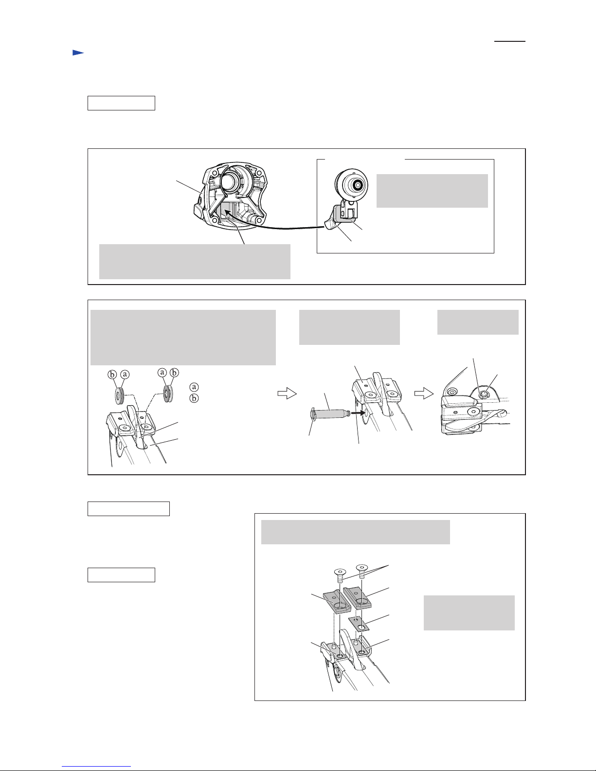
Center blade
Side blade (L)
Side blade (R)
Charger DC18SD
Charger DC18SE (for automobile cigarette lighter socket)
Charger DC24SC
Battery BL1430 (for BJS100 only)
Battery BL1830 (for BJS101 only)
Fast charger DC18RA
Note: The standard equipment for the tool shown above may vary by country.
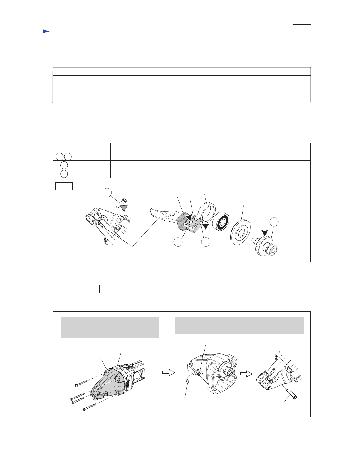
Hex wrench 3 .................................... 1
These products are available in the following variations.
All models also include the accessories listed below in "Standard equipment".
Dimensions: mm (")
Width (W)
Height (H)
Length (L) 364 (14-3/8)
78 (3-1/16)
103 (4-1/16) 118 (4-5/8)
BJS100 BJS101
BJS101
Models BJS100 and BJS101 have been developed as sister models of
cordless straight shears BJS160 and BJS161.
BJS100 is powered by 14.4V/3.0Ah Li-ion battery BL1430, and BJS101
is powered by 18V/3.0Ah Li-ion battery BL1830.
Ability to cut curves with minimum cutting radius of 30mm (1-3/16”) is
obtained by mounting the blades of Model JS1670 on BJS160/ BJS161.
Note: 1.3Ah Li-ion battery BL1415/ BL1815 cannot be used for BJS100/ BJS101.
*Weight according to EPTA-Procedure 01/2003, including battery
Battery
Max cutting capacities:
mm (Ga)
Steel with tensile strength
up to 600N/mm2
Cell
Voltage: V
Capacity: Ah
Li-ion
14.4 18
3.0
Net weight*: kg (lbs) 1.9 (4.2) 2.0 (4.4)
0.7 (23)
Aluminum with tensile
strength up to 200N/mm22.5 (12)
Steel with tensile strength
up to 400N/mm21.0 (20)
No load speed: min-1=spm (strokes per minute) 4,300
Max output (W)
Minimum cutting radius: mm (") 30 (1-3/16)
Overload protection by current limiter Yes
280 350
Specification Model BJS100 BJS101
22 with DC18RACharging time (approx.): min.
BJS100RFE
BJS100Z
BJS100
Model No. Offered to
All countries
Mexico, Panama
All countries except the two listed above
BL1430
(Li-ion 3.0Ah) DC18RA
No No No
type quantity Charger
Yes
No
Plastic
carrying case
2 1
Battery Battery
cover
BJS101RFE
BJS101Z
BJS101
Model No. Offered to
All countries
Mexico, Panama
All countries except the two listed above
BL1830
(Li-ion 3.0Ah) DC18RA
No No No
type quantity Charger
Yes
No
Plastic
carrying case
2 1
Battery Battery
cover
BJS100
BJS101
T
ECHNICAL INFORMATION
L
H
W
BJS100

P 2/9
Repair
CAUTION: Remove the Battery from the machine for safety before repair/ maintenance
in accordance with the instruction manual!
[1] NECESSARY REPAIRING TOOLS
[2] LUBRICATIONS
[3] DISASSEMBLY/ASSEMBLY
[3]-1. Center blade
Fig. 1
Fig. 2
Code No. Description Use for
1R036 Bearing setting plate 17.2 Holding Helical gear 34 when removing Crank shaft
1R269 Bearing extractor (small) Removing Ball bearings
1R366 Feeler gauge set Adjusting the gap between Center blade and Side blades
Item No.
Apply Makita grease FA.No.2 to the following portions designated in the black triangle to protect parts
and product from unusual abrasion.
And to the portion designated in gray triangle, apply the lubricant VG100.
Description
17 18
Sealing screw
Rod
Link
Dust cover
1) Disassemble Shearing mechanism from Crank housing complete as illustrated in Figs. 2, 3.
Center blade
32
Portion to lubricate
DISASSEMBLING
Pin 7
17 18 Pin 5
25 Pin 7
32 Helical gear 34
Drum portion for smooth action of Center blade and Rod
Drum portion for smooth action of Center blade.
Teeth portion for smooth engaging with Armature’s gear
1. Remove four 4x50 Tapping screws,
then separate Crank housing complete
from Gear housing complete.
2. Remove Stop ring E-4 from Pin 7, then remove Pin 7
from Crank housing complete.
Stop ring E-4
Makita grease FA.No.2
a little
a little
Lubricant Amount
30g
VG100
25
Crank housing
complete
Gear housing
complete
Pin 7

[3] DISASSEMBLY/ASSEMBLY
[3]-1. Center blade (cont.)
DISASSEMBLING
ASSEMBLING
Flat washer 5
Center blade
Pin 5
Dust cover
Fig. 3
Fig. 4
Fig. 5
Fig. 6
2) Center blade can be disassembled from Shearing mechanism as illustrated in Fig. 4.
1) Assemble Shearing mechanism as described in Figs. 5, 6.
3. Shearing mechanism can now be from Crank housing complete by hand.
Note: Be careful not to lose the washers.
Thin washer 7
Teflon washer 7
Shearing mechanism
Dust cover has to be assembled to
Center blade as illustrated below left.
Center blade
Center blade
Dust cover
Dust cover
(made of sponge)
[Correct] [Wrong]
Flat washer 5
Flat washer 5
Link
Pin 5
Pin 5Link
Assemble Center blade and
two Flat washers to Link
as illustrated left.
P 3/9
Repair

[3] DISASSEMBLY/ASSEMBLY
[3]-1. Center blade (cont.)
ASSEMBLING
ASSEMBLING
Fig. 7
Fig. 8
Dust cover
Insert Pin 7 through
Crank housing complete
from Side blade R side.
Secure Pin 7 with
Stop ring E-4.
Insert Thin washer 7 and Teflon washer 7
into the space between Center blade and
Crank housing complete as illustrated below;
one set each into the both sides of Center blade.
Be sure to place Thin washer 7 on the blade side. Side blade R
Stop ring E-6
Pin 7
Crank housing
complete
2) Mount the assembled Shearing mechanism on Crank housing complete as illustrated in Figs. 7, 8.
Then assemble Crank housing complete to Gear housing complete. (Refer to Fig. 2.)
Pin 7
Stop ring E-4
[3]-2. Side blades R and L
DISASSEMBLING
Side blade section can be disassembled
as described in Fig. 9.
Do the reverse of the disassembling steps.
Note: Be sure to assemble Spacer between
Slip plate L and Side blade L
as illustrated in Fig.9.
Fig. 9
Side blades R and L can be removed by removing
M5x10 Hex Socket countersunk screw.
M5x10 Hex socket
countersunk screw
Spacer is assembled
between Side blade L
and Slip plate L.
Side blade R Side blade L
Spacer
Slip plate L
Slip plate R
P 4/9
Repair
Shearing mechanism
Center blade
Fitting Dust cover in this rectangular depression,
assemble Shearing mechanism to Crank housing
complete.
Make sure that Dust cover
is assembled to Center blade
as described in Fig. 5.
Thin washer 7
Teflon washer 7
Center blade
Crank housing
complete

[3] DISASSEMBLY/ASSEMBLY
[3]-3. Helical gear 34, Ball bearings 627DDW, 6000ZZ, 696ZZ
ASSEMBLING
Fig. 10
Fig. 11
Fig. 12
Remove three Ball bearings from Crank shaft
using 1R269.
Then remove Helical gear 34 and Sealing screw
using arbor press and 1R036.
Center blade section
Shearing mechanism
Ball bearing 627DDW
Ball bearing 6000ZZ
1) Disassemble Shearing mechanism from Crank housing complete as illustrated in Figs. 2, 3.
2) Disassemble Center blade section as illustrated n Fig. 10.
DISASSEMBLING
Ball bearing 696ZZ
Ball bearing
627DDW
Ball bearing
6000ZZ
Ball bearing
6000ZZ
Ball bearing
627DDW
Ball bearing
696ZZ
Flat
washer 7 Link
Ball bearing
696ZZ
1R036 Helical gear 34
Helical
gear 34
Sealing screw
Note:
Sealing screw is directional
when assembled to Crank shaft.
Be sure to face the side having
lower step towards Helical gear 34.
Note:
Do not forget to assemble
Flat washer 7 between
Ball bearing 6000ZZ and
Ball bearing 627DDW.
Sealing screw
Sealing screw
Flat washer 7
Helical gear 34
Crank shaft
Helical gear 34
3) Remove Ball bearings, Sealing screw and Helical gear 34 from Crank shaft. (Fig. 11)
Assemble Helical gear 34, Sealing screw and Ball bearings to Crank shaft,
then assemble Link to Ball bearing 6000ZZ. (Fig. 12)
Crank shaft
P 5/9
Repair

[3] DISASSEMBLY/ASSEMBLY
[3]-4. Armature
Fig. 13
DISASSEMBLING
ASSEMBLING
Disassemble Armature as illustrated in Fig. 13.
2. Remove Holder cap and Carbon brush from the both side
of Housing, then separate Crank housing and Gear housing
from Housing by removing four 4x50 Tapping screws.
Holder cap cover
Do the reverse of the disassembling steps.
Crank housing
Brush holder cap
3. Pull off Armature from Housing set.
1. Remove Holder cap cover from Housing
by levering it up with slotted screwdriver.
Gear housing
Housing
Carbon brush
P 6/9
Repair
Armature

[4] ADJUSTMENT
Adjustment of Blade Clearance
Fig. 14
The blade clearance between Center blade and each of the two Side blades should be 0.2mm.
If the clearance is not correct, adjust it to 0.2mm using Feeler gauge set (No.1R366) as described in Fig. 14.
1) Loosen M6x10 Hex socket set screw
by turning it counterclockwise
about one turn with Hex wrench 3.
Note: Do not remove this screw.
2) Insert 0.2mm leaf of Feeler gauge set (No.1R366) into the clearance A, and insert 0.05mm leaf and
0.15mm leaf into the clearance B.
4) After adjusting the clearance, remove leaves of Feeler gauge, then tighten M6x10 Hex socket set screw
by turning it clockwise with Hex wrench 3.
3) Turn M4x25 Hex socket head bolt with Hex wrench 3 until each clearance is adjusted to 0.2mm.
M6x10 Hex socket set screw
(located on the side of
Side blade R)
Hex wrench 3
Feeler gauge leaf to insert into the clearance
0.2Leaf thickness: mm 0.05 + 0.15
Clearance A Clearance B
P7/9
Repair
Feeler gauge set (No.1R366)
Side blade L
Center blade
Side blade R
Clearance A Clearance B
Side blade L
Center blade
Side blade R
0.05mm Feeler gauge leaf
plus
0.15mm Feeler gauge leaf
M4x25 Hex socket head bolt
(located on the side of
Side blade L)
Hex wrench 3
0.2mm Feeler gauge leaf
Clearance A Clearance B

Circuit diagram
Wiring diagram
Color index of lead wires' sheath
Black
Red
Controller
Terminal Connector
Switch
Endbell
Complete LED Circuit
Fig. D-1
Fig. D-2
Endbell complete
Switch Switch knob
1) Bearing box portion
2) Lead wire holder portion
1) Be sure to place Bearing box portion on Switch side.
Otherwise, Armature cannot be assembled to Endbell complete.
2) Be sure to place Lead wire holder portion on the opposite side of Switch lever.
Otherwise, Lead wires cannot be connected.
Switch lever
P 8/9
[1] Endbell Complete

Wiring diagram
Switch
Switch, viewed from
Housing L side
Insulated connector
Switch lever
Endbell complete
Housing L
Controller
Switch knob
Space for
Yoke unit
LED circuit
Fig. D-3
Switch button
Wire connecting
portion
Flag connectors have to be so connected that
their wire connecting portions are placed over
the marks of pole.
rib
notch
Fitting the notch of Yoke unit over the rib of Housing L,
assemble Yoke unit to Housing L.
Yoke unit
P 9/9
Terminal
Wire connecting
portion
Flag connector
Terminal
Mark of pole
Put Sensor-matic chip in this space if used.
Fix the Lead wires of LED circuit
with this Lead wire holder.
Pass the Lead wires between
Housing L and Controller.
Housing L
Insulated connectors have to be so connected to Switch
that their wire connecting portions are placed on the
opposite side of Switch button.
[2] Housing L
This manual suits for next models
5
Table of contents
Other Makita Power Tools manuals

Makita
Makita HR4002 User manual

Makita
Makita DUX60 User manual

Makita
Makita DJN160 User manual

Makita
Makita UP100D User manual

Makita
Makita 4326 User manual

Makita
Makita RP1100 User manual

Makita
Makita RT0700C User manual

Makita
Makita DFL651F User manual

Makita
Makita SG1251 User manual

Makita
Makita XWT07XV User manual

Makita
Makita 4324 User manual

Makita
Makita TW160DZJ User manual

Makita
Makita BJS130 User manual

Makita
Makita VR250D User manual

Makita
Makita 4350T User manual

Makita
Makita DTW284 User manual

Makita
Makita 4340T User manual

Makita
Makita DHR280 User manual

Makita
Makita DPP200 User manual

Makita
Makita XWT19 User manual