08 09
will be affected by the induction of current or voltage.
When the resistance of auxiliary earth bars exceeds
2KΩ it may result in measurement errors. Therefore, be
careful in sticking the auxiliary earth bars P1 and C1
into the moist earth. Also, ensure sufficient connections
between the respective terminals and lead wires.
4-2 Earth voltage measurement of earthed
equipment under test
Press the AC V button and check earth voltage. Earth
voltage will be indicated on the V scale. When earth
voltage is more than 5V it may result in errors in earth
resistance measurement. To avoid this make earth
resistance measurement after turning off the power
source of the equipment under test or reducing earth
voltage.
Note:
Even when either of range switch buttons x1Ω,
x10Ω and x100Ω is pressed it does not affect earth
voltage measurement.
4-3 Checking battery voltage & lead wire connection
With ”BATT.CHECK” button pressed, the following can
be checked simultaneously:
4-3-1 Battery voltage
Battery voltage is sufficient when the meter pointer
stays in GOOD area of the battery check scale. If not,
replace with the new batteries in accordance with
instructions given in section 5.
4-3-2 Lead wire connection
“OK” lamp lights up when lead wire connection to P
and C terminals is good and earth resistance of
auxiliary earth is within a limit of tolerance. If it does
not illuminate, check for lead wire connection to P and
C terminals or lower auxiliary earth resistance to a
proper level by changing earth bar location or making
the ground moist with water.
Red and yellow lead wires can be checked for possible
breakage by shorting the alligator clips at the end of
each wire.
NOTE:
There is no need for lead wire connection when
battery voltage only is checked. Simply push
“BATT.CHECK” button. “OK” lamp will not
illuminate.
4-4 Earth resistance measurement
Press either of x1Ω,x10Ω and x100Ω range switch
buttons. Then press the “MEAS.” Button. Multiply the
reading by 10 at x10Ω or 100 at x100Ω.
“OK” lamp is on when the instrument is in normal
operation. If not, it indicates an excessive earth
resistance across C and E terminals that does not
permit a normal operation. Recheck for possible
contact between each lead wire and earth resistance
of auxiliary earth bars in accordance with the
instructions give in section 4-3. In case “OK” lamp does
not illuminate and the meter pointer deflects up full
scale despite all preceding checks, possible causes
are considered an abnormal condition existing in
earthed equipment under test, breakage of connection
wires from that equipment or breakage of the green
lead wire.
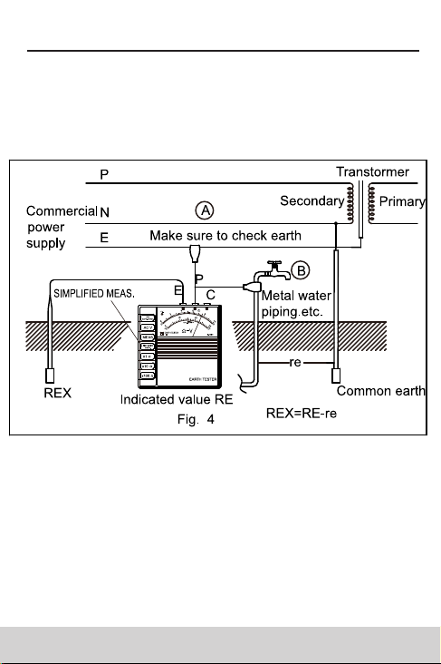
4-5.Simplified earth resistance measurement method
4-5-1 This method is recommended where an earth
resistance higher than 10 ohms is measured or where
it is not possible to drive auxiliary earth bars. An
approximate value of earth resistance can be obtained
by the two wire system which utilizes existing earthed
equipment as shown in Fig.4.
4-5-2 Measurement methods are illustrated in Fig.4.
NOTE:
When making earth resistance measurements
using commercial power supply(A),make sure that
earth side is connected to P terminal.
4-5-3 Press “AC V” button as outlined in section 4-2 for
earth voltage measurement of equipment under test
and make certain that earth voltage is below 2V.
4-5-4 First press “x10Ω” button and “MEAS.” button
next Then read earth resistance. When the meter
pointer deflects up full scale, press “x100Ω” button.
The reading obtained (RE) is and approximate earth
resistance value. There is no need for external
shorting as P and C terminals are internally shorted.
Since measuring current is as low as 2mA, the earth
leakage breaker (ELCB) does not trip even if the earth
side of the commercial power supply with an ELCB is
used.
“OK” lamp is illuminated when the instrument is in
normal operation, whether the simplified measurement
or normal measurement method is employed.
4-5-5 When the instrument is in working condition, “OK”
lamp is illuminated whether the simplified or ordinary
measurement is made (This indicates continuity
between P plus C terminals and E terminal).However,
lead wire connection to P plus C terminals and E
terminal). However, lead wire connection to P and C
terminals cannot be checked even when “BATT.
CHECK” is pressed as the lead wire is not connected
to C terminal.
4-5-6 In case of the simplified measurement method
where the two terminals only are used, earth
resistance “re” of an earthed electrode connecting to
P terminal will necessarily be added to a true earth
resistance value “REX”. Therefore, the earth
resistance reading is given as:
RE=REX+re.
If “re” is a known value as follows:
Supposing that RE is 100Ω and an earth resistance to be
measured is 100Ω,for example, the true earth resistance
value may be expressed as:
REX=(100Ω)-re.
Since re is greater than 0(zero),a true earth resistance
may be give as:
REX≤100Ω
In case we measure earth resistance not greater than
several tens of ohms we may consider the earth
resistance reading obtained as a true value.
10
5 Battery replacement
1. Raise the panel by 90 degrees until it locks.
2. Push the “Holder” pressing the upper section of the
battery case toward the panel as shown in Fig.5.
The battery case will come up.
3. Then, pull out the battery case.
4. Remove the battery hook on the bottom of the
battery case. Empty the battery case and install new
batteries.
5. Eight pieces of AA battery are used Install them
according to the markings on the battery case.
6. Fit in the battery hook with polarity in correct position
and push back the battery case until it catches the
holder.
SAFETY WARNING
1. this instrument must be used by a competent,
trained person and operated in strict accordance
with the instructions.
2. my company will not accept liability for any damage
or injury caused by misuse or non-compliance with
the instructions or safety procedures.
3. it is essential to read and understand the safety
rules contained in the instructions. they must be
observed when using the instrument.
00-05-0922
06 07
ANALOG EARTH RESISTANCE TESTER ANALOG EARTH RESISTANCE TESTER ANALOG EARTH RESISTANCE TESTER ANALOG EARTH RESISTANCE TESTER ANALOG EARTH RESISTANCE TESTERANALOG EARTH RESISTANCE TESTER