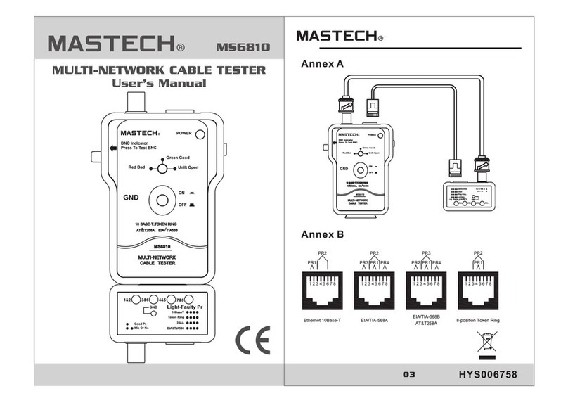
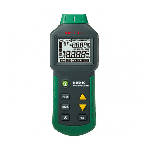
Mastech MS2309 User manual

Low Resistance Tester
MS2309
CAT III
600 V
TEST
HOLD LOCK
REL
DATE
TIME
Ω
V
AF
B C D E
ALL
AF
B C D E
ALL
COMP
MEMO READ

Contents
01 0 2
Low resistance tester (hereafter known as the 'meter') is designed and manufactured according to the EN61010 safety
standard, along with safety requirements for electronic measuring instruments with a over voltage rating of CAT III 600V
and a pollution degree of 2.
This manual covers general safety guidelines and warnings to help prevent personal injury and to ensure long life for the
meter. Please read and follow all instructions and safety guidelines within this manual.
1. Overview and Safety Information
CAUTION Indicates actions could cause serious or fatal injury.
WARNING
ATTENTION
Indicates misuse or improper operation could cause serious or fatal injury.
Indicates actions could cause injury or damage to the meter.
1. Overview and Safety Information
2. Description
2.1 Buttons and Components
2.2 Display
3. Specifications
3.1 Accuracy
3.2 Measurement Conditions
3.3 Operating Temperature and Humidity
3.4 Storage Temperature and Humidity
3.5 Battery
3.6 Dimensions
3.7 Weight
3.8 Accessories
4. Operation Instructions
4.1 2 Pole Resistance Measurement
4.2 4 Pole Resistance Measurement
4.3 Voltage Measurement
4.4 Storing Measurement Data
4.5 Reading Stored Data
4.6 Relative Measurement
4.7 Date and Time
4.8 Compare Measured and Set Values
4.9 Backlight
4.10 Saving Data using USB
5. Replacing the Batteries
....................................................................................................02
.............................................................................................................04
.....................................................................................................................................07
................................................................................................................09
.....................................................................................................................................04
........................................................................................................................................06
.................................................................................................................................07
.............................................................................................................07
............................................................................................07
..............................................................................................07
.......................................................................................................................................07
..................................................................................................................................07
.......................................................................................................................................07
................................................................................................................................07
...................................................................................................................08
...................................................................................................08
...................................................................................................08
...........................................................................................................09
....................................................................................................................09
.................................................................................................................09
.............................................................................................................................10
...............................................................................................10
.....................................................................................................................................10
...............................................................................................................10
....................................................................................................................11

03 0 4
CAUTION
- Always move the rotary switch to the proper position before beginning measurement.
- Do not operate the meter around explosive gas, vapor, or dust.
- Never use the test leads or open the case while hands are wet.
- When measuring, always keep your fingers behind the probe guards.
- Do not operate the Meter with the case (or part of the case) removed.
WARNING
ATTENTION
- Do not use the meter if any abnormalities or damage to the meter exist.
- Any adjustments or repair to the meter should be done by qualified personnel only. If the meter is
damaged or needs repair, contact your local retailer.
- Do not allow any moisture inside the case or battery compartment.
- Remove the test leads and turn the rotary switch to the off position before replacing the batteries.
- Always make sure the test leads are correctly inserted into input jacks before measurement.
- If the meter is not going to be used for an extended amount of time, remove the batteries to prevent
damage to the meter.
- Do not expose the meter to direct sunlight, high temperature, humidity or moisture.
- Use a mild detergent or damp cloth to clean the meter. Do not use abrasives or solvents.
- Do not use the instrument with moisture on the input jacks.
2. Description
This meter is designed for many situations, such as power distribution lines, interior grounding wires, transformer resistance
testing, with 2 or 4 wire resistance measurement modes and AC voltage measurement.
The meter has a large, easy to read, backlit LCD screen with the ability to store up to 1000 sets of data.
The meter's save data persists after turning off the meter, so data from previous uses can easily be recalled and used for
comparison or relative measurement.
2.1 Buttons and Components
Item Button Function
1Rotary Switch To switch between measurement functions (ground voltage, 2 or 4 wire resistance
measurement)
2 SELECT Button Select comparison save slot
3 HOLD Button To hold the current reading on the display
4 LIGHT Button To turn on/off the backlight
5 Display Shows measurement and stored data
6 READ Button To view stored data
7 To select storage slot for stored data
8 MEASURE Button To start/end resistance measurements
9 To select a storage slot for stored data/switch to relative measurement
10 TIMER Button To switch between date and time display
11 ENTER Button To select active data storage slot
12 COMP Button To compare measurements and stored data
13 MEMO Button To store displayed data
14 4W Input Jacks Use these input jacks for 4 wire systems
15 2W Input Jacks Use these input jacks for 2 wire systems
Button
REL Button

05 0 6
TEST
HOLD LOCK
REL
DATE
TIME
Ω
V
AF
B C D E
ALL
AF
B C D E
ALL
COMP
MEMO READ
1
2
3
4
5
7
8
6
910 11 12 13
2.2 Display
Symbol Function
TEST
HOLD LOCK
REL
DATE
TIME
Ω
V
AF
B C D E
ALL
AF
B C D E
ALL
COMP
MEMO READ
Display symbols:
TEST
>A
REL
MEMO
2POLE
V
Measurement in progress
Measured value is greater than the compared values
Relative measurement
Stored data slot selection
2 wire resistance mode
Volts (voltage)
Auto power off
Alternating current
Symbol Function
Date display
Measured value is less than the compared values
View stored data
USB connection active
4 wire resistance mode
Ohms (resistance)
Low battery
Warning symbol
DATE
<A
READ
4POLE
Ω

07 0 8
Specified for temperatures of 23°C ±5°, relative humidity <75%
3. Specifications
3.1 Accuracy
Range
2 wire resistance
4 wire resistance
AC voltage
4Ω, 40Ω, 400Ω
AC600V(50/60HZ)
Accuracy
±(0.5% + 5 digits)
4Ω, 40Ω, 400Ω ±(0.1% + 5 digits)
±(2% + 5 digits)
For low resistance measurements using a test current of a maximum of 250mA DC by average value rectification.
3.2 Measurement Conditions
0-40°C; relative humidity: <85%
3.3 Operating Temperature and Humidity
-10~50°C; relative humidity: <85%
3.4 Storage Temperature and Humidity
8x1.5V AA batteries
3.5 Battery
330x125x365mm
3.6 Dimensions
3.45kg
3.7 Weight
Test leads x4; Software CD x1; Manual x1
3.8 Accessories
4. Operation Instructions
Do not attempt to measure more than 600V AC in voltage mode.
To avoid damage to the meter, do not apply voltage to the input terminals when measuring resistance.
CAUTION
To avoid false readings that could lead to damage to the meter or injury, replace the batteries as soon as the low battery
symbol " " appears. See Replacing the Batteries section for instructions.
Connect the test leads to the 2W input jacks and turn the rotary switch to the 2POLE position. Connect the leads to the ends
of the resistance to be measured and press MEASURE. The test symbol will appear on the display and the button will light up.
Once measurement is complete, the button's light will turn off and the measurement will be shown on the display.
NOTE:
Use the 4 pole method or switch to relative measurement after connecting leads for a more accurate measurement when
measuring very small resistances. This is to eliminate the resistance of the leads themselves and provide a more accurate
reading.
4.1 2 Pole Resistance Measurement
This method uses the 2W jacks to provide a constant current through the resistance and the 4W jacks to measure the voltage
across the resistance. This will effectively eliminate the resistance of the circuit or the leads themselves.
Turn the rotary switch to the 4POLE position. Connect the red leads to one side of the resistance and the black leads to the
other and press MEASURE. The test symbol will appear on the display and the button will light up. Once measurement is
complete, the button's light will turn off and the measurement will be shown on the display.
NOTE:
The 4W jacks are the sampling voltage. For the most accurate results, connect the two 4W leads as close as possible to the
resistance being measured.
4.2 4 Pole Resistance Measurement

09 1 0
Turn the rotary switch to the V~ position. Insert the test leads into the 2W input jacks and connect the leads to the circuit
under test. The measured AC voltage will be displayed.
NOTE:
Do not attempt to test voltages that may exceed 600V AC.
4.3 Voltage Measurement
The tester can store up to 1000 readings in its internal memory. Memory is held even when powering off the tester.
1. After making a resistance measurement, press MEMO. The memory slot number is displayed on the right side of the
display. Press MEASURE and the reading will flash, indicating that the value has been stored in the displayed memory slot.
2. The tester will automatically select the next highest memory slot when pressing MEMO.
3. To select a different memory slot, press the up or down button to change the selected memory slot.
4.4 Storing Measurement Data
To read stored values:
1. Press READ. The memory slot appears in the bottom right of the display and the stored reading is shown on the main display.
2. Press up or down to move through the stored values.
3. Press ENTER to return to normal display.
4.5 Reading Stored Data
Relative measurement is only available in resistance mode.
1. After making a measurement, press REL to enter relative mode. The tester stores the value that was displayed and
compares any subsequent measurement to the stored value. (REL = current reading - stored value)
2. Relative mode cannot be activated until the measurement process has completed.
3. The new measurement (current reading) cannot exceed the stored value's range, otherwise the display will only show 'OL'.
4.6 Relative measurement
The date or time can be shown at the top of the display. Pressing TIMER will switch between time and date display.
To set the data and time:
1. Hold TIMER when turning on the tester. The flashing value can be adjusted by pressing the up or down buttons. Press
TIMER to change the flashing value.
2. Once the time and date have been set, press ENTER to return the display to normal.
4.7 Date and Time
Pressing COMP after measurement will compare the current reading to a set of stored values and indicated whether or not
the current reading is higher or lower than those stored values.
To set stored values:
1. Hold COMP when turning on the tester. The display will show a value and a save slot (A-F).
2. To adjust the value, press the up and down arrows. Press COMP to move the decimal point within the value.
3. Once the desired value is set, press MEASURE and the value will flash indicating it's been saved.
4. Press SELECT to change save slots. Repeat steps 2 and 3 for each slot needed.
5. Once all values are set, press ENTER to return the display to normal.
4.8 Compare Measured and Set Values
Press LIGHT to turn the backlight on. Press LIGHT again to turn the backlight off.
4.9 Backlight
The tester can send data to be stored on a PC using the included USB cable.
1. Install the included software on the PC to be used and connect the tester to the PC using the included USB cable.
2. Press READ to view the stored data on the tester.
3. Select the reading you wish to transfer to the PC and press MEASURE. The USB symbol will appear in the top left of the
display, indicating communication with the PC is active.
4. Once the transfer is complete, the USB symbol will disappear. Press ENTER to return the display to normal.
4.10 Saving Data Using USB

11
5. Replacing the Batteries
Do not attempt to replace the batteries if the tester is wet.
Do not open the battery cover during measurement.
Always turn the rotary switch to the off position before opening the battery cover.
Remove the test leads from the input jacks before opening the battery cover.
CAUTION
Do not mix old and new batteries.
Always note the polarity when inserting batteries.
NOTE
1. Unscrew the battery cover and remove it from the back of the tester.
2. Remove the old batteries and replace them with new ones.
3. Return the battery cover and tighten the screws.
R-00-05-1918
Table of contents
Other Mastech Test Equipment manuals

Mastech
Mastech MS5910 User manual

Mastech
Mastech MS2601 User manual

Mastech
Mastech MS5215 User manual

Mastech
Mastech MS6810 User manual

Mastech
Mastech Analog Earth Resistance Tester User manual

Mastech
Mastech KPS-TL300 User manual

Mastech
Mastech MS2302 User manual

Mastech
Mastech MS8910 User manual

Mastech
Mastech MS7222 User manual

Mastech
Mastech MS2301 User manual
Popular Test Equipment manuals by other brands

Anritsu
Anritsu MX183000A Operation manual

KS Tools
KS Tools 550.7560 operating instructions

Steinberg Systems
Steinberg Systems SBS-BT-612 user manual

Kenwood
Kenwood CS-1100 instruction manual

Magnaflux
Magnaflux P-70 installation guide

Smith & Larson Audio
Smith & Larson Audio Woofer Tester Quick reference guide