30119-24 Rev. 10.9/07-09
4
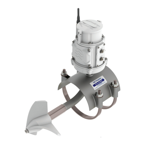
6. METER can now be placed carefully onto the
brackets allowing the lower bracket to slide into the
lower guide and then sliding the upper bracket into
position.
7. PROPELLER POSITION should be double checked
to make certain the propeller rides in the center of
the pipe and is parallel to flow. Adjust brackets, if
necessary, and make sure that all bolts are tightened
securely.
8. PADLOCK can be inserted through the hasp
cast into the upper bracket to eliminate unauthorized
removal of the meter from the pipeline.
ELECTRONIC OPEN FLOW METER
OPERATION AND MAINTENANCE MANUAL
III. MCCROMETER products have been carefully designed
to be as maintenance free as possible. Periodic pre-
ventive maintenance, however, is highly recommended
and should be practiced according to schedule to
assure continuous accuracy and trouble-free perfor-
mance of your propeller meters. The maintenance and
inspection procedure can also be used as a guide to
locating a problem in the unit that may be the cause
of abnormal meter operation.
Routine preventative maintenance should be performed
on all meters, which includes cleaning and an inspection
of the propeller and its bearing. The interval between
inspections depends on the water quality and the usage
of the meter The initial inspection should be performed
after one to two years of service, to determine the
period between future inspections. After five to ten
years, the complete meter should be inspected to
ensure years of dependable service.
IV. METER ASSEMBLY should be removed from the
service position by removing padlock, if any, from the
upper bracket and lifting the meter off of the support
brackets. Care should be exercised when removing the
meter to avoid propeller blade damage that can occur
if the propeller is bumped against the lower guide or
inside of pipe during removal.
V. WORKING AREA chosen for disassembly and reassem-
bly of the meter components should be clean to reduce
the chance of dust or dirt particles being introduced
into the propeller area.
VI. DISASSEMBLY AND INSPECTION OF METER
should include cleaning the propeller assembly (#1),
ceramic sleeve bearing separator assembly (#12), and
drive magnet (#9).
1. PROPELLER REMOVAL can be accomplished by
first removing the thrust bearing cartridge assembly (#5).
Loosen the set screw (#3) in the side of the nose of
the propeller. Remove the thrust bearing cartridge
(#5) by turning it counterclockwise while holding the
propeller in place.
2. REVERSE THRUST BEARING CARTRIDGE (#6)
must now be removed. Turn the propeller (#2) so that
the allen wrench clearance hole is lined up with the set
screw in the side of the reverse thrust bearing cartridge
(#6). The location of the set screw is marked by a small
hole drilled in the face of the reverse thrust bearing
cartridge. With a 5/64 inch allen wrench, loosen the
set screw (#7) in the reverse thrust bearing cartridge
(#6) two to three turns, which will allow the cartridge
to be unscrewed without damaging the spindle thread.
NOTE: If the bearing area appears to be clogged with
dirt or sediment, making it difficult to locate the set
screw (#7) or to allow the allen wrench to fit into
the set screw socket, then the bearing area should be
flushed out with water. Insert Tool T-2402X-1
into the
propeller through the threaded nose. The tabs in the
tool should engage in the screwdriver slot in the end
of the reverse thrust bearing cartridge (#6). Remove
the propeller assembly (#1) and reverse thrust bearing
cartridge (#6) by turning Tool T-2402X-1 counterclock-
wise unscrewing the reverse thrust bearing cartridge (#6)
from the spindle (#12). The propeller assembly with
reverse flow cartridge will now slide off the spindle.
WARNING: If the reverse thrust cartridge does not
unscrew easily, it may be because the set screw was
not unscrewed enough. If unscrewing the reverse flow
cartridge is continued with the set screw binding on
spindle thread, damage to thread could occur.
3. WATER LUBRICATION of the ceramic sleeve
bearing (#12) is achieved by means of two openings
in the end of the thrust bearing cartridge (#5) which
allow air to be purged from the bearing area. These
should be cleared of any foreign material by running
a small wire through the holes on either side of the
screwdriver slot.
4. CERAMIC BEARING CARTRIDGE (#8) and drive
magnet (#9) should be cleaned of any foreign mate-
rial and inspected for damage. Using a bottle brush,
thoroughly clean the ceramic bearing surface (#8) and
inside diameter of the magnet (#9). After cleaning the
propeller, flush the inside out with water. The outside
surfaces of the propeller should also be cleaned to as-
sure a smooth, unrestricted flow across the surface
of the propeller. Do not use an oil based solvent in
cleaning, as damage to the assembly could occur.
5. SPINDLE CERAMIC SLEEVE (#12) and the O.D.
or surface of the separator (#12) should be cleaned
and inspected for any substantial amount of wear.
The thrust bearing (#26) should be checked for any
damage. If it is determined that the spindle ceramic
sleeve or separator (#12) are worn sufficiently, the
separator/support spindle assembly (#12) should be
replaced.


