MEDC DB1 User manual

© Eaton MEDC Ltd 2018 01/18
Technical Manual for the Sounders – DB1 & DB1H
Manuel technique pour sondeurs DB1 et DB1H
Technisches Handbuch für die Summer DB1 und DB1H
Manual Técnico para os dispositivos de
sinalização audível – DB1 e DB1H
Please note that every care has been taken to ensure the accuracy of our technical manual. We do not, however,
accept responsibility for damage, loss or expense resulting from any error or omission. We reserve the right to make
alterations in line with technical advances and industry standards.
Toutes les précautions ont été prises pour garantir l'exactitude du contenu de cette notice technique. Néanmoins,
nous déclinons toute responsabilité à l'égard des éventuels dégâts, pertes ou frais résultant de la présence dans
cette documentation d'une quelconque erreur ou omission. Nous nous réservons le droit d'apporter à cette notice
toute modification rendue nécessaire du fait de progrès techniques ou de l'évolution des normes industrielles.
Es wurden alle erforderlichen Maßnahmen getroffen, um die Genauigkeit unseres technischen Handbuchs
sicherzustellen. Wir übernehmen allerdings keine Haftung für Schäden, Verluste oder Kosten, die durch Fehler oder
Auslassungen entstehen. Wir behalten uns vor, entsprechend der technischen Fortschritte und Branchenstandards
Änderungen vorzunehmen.
Nota que foram feitos todos os esforços para assegurar a ausência de erros no nosso manual técnico. No entanto,
não no responsabilizamos por eventuais danos, perdas ou despesas que possam resultar de algum erro ou omissão.
Reservamos o direito de efectuar alterações para reflectir avanços técnicos e normas da indústria.

01/18 © Eaton MEDC Ltd 2018

English
1.0 INTRODUCTION
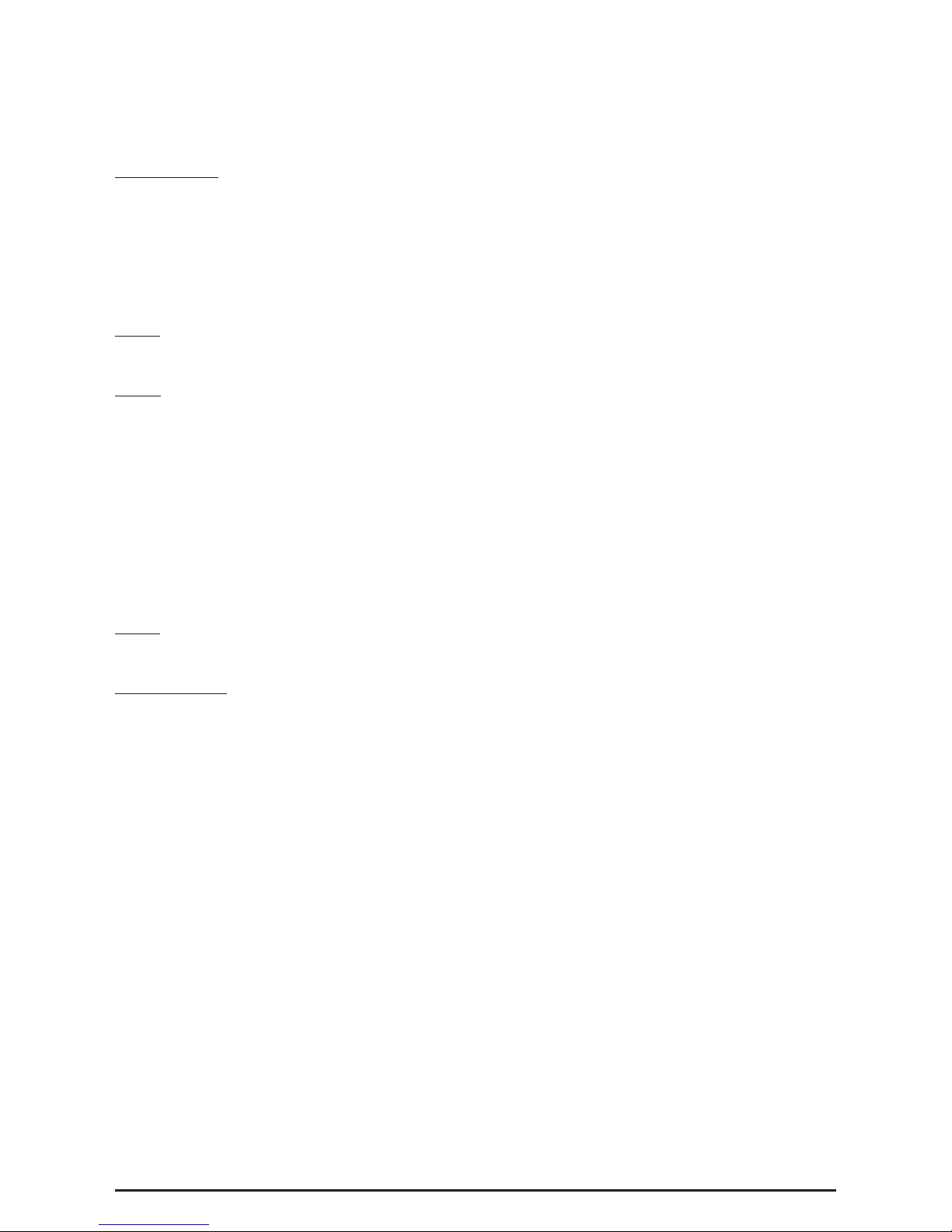
This range of light weight, flameproof sounders has been designed with a high weatherproof rating to cope with
the harsh environmental conditions found offshore and onshore in the oil, gas and petrochemical industries
New electronic circuitry allows the DB1 and DB1H to be switched between two user selectable tones by either
reversing the polarity, or connecting a second voltage supply (dual tone facility is available on dc units only).
The higher output DB1H is particularly suitable for noisy environments.
2.0 INSTALLATION
General
When installing and operating explosion-protected equipment, requirements for selection, installation and op-
eration should be referred to e.g. IEE Wiring Regulations and the ‘National Electrical Code’ in North America.
Additional national and/or local requirements may apply.
Ensure that all nuts, bolts and fixings are secure.
Ensure that only the correct listed or certified stopping plugs are used to blank off unused gland entry points
and that the NEMA/IP rating of the unit is maintained. MEDC recommend the use of a sealing compound such
as ‘HYLOMAR PL32’ on the threads of glands and stopping plugs in order to maintain the IP or NEMA rating
of the unit.
The sounder is mounted via the 2 off Ø9mm fixing holes. The fixing holes have been designed to accept an M8
screw or bolt.
MEDC recommend the use of stainless steel screws.
The unit has been designed and certified to operate at any attitude – from horizontal to vertical however, it is
important to note that the alignment of the sounder should ensure that:-
1. Dust or debris cannot lodge or settle in the re-entrant horn
2. Water from hoses, jets or rain cannot settle in the re-entrant horn
Cable Termination
CAUTION: Before removing the cover assembly, ensure that the power to the unit is isolated.
Unscrew the 4 off M6 screws (5.0mm A/F hexagon key) holding the cover assembly to the base. Keep screws
in a safe accessible place as they are not retained in the cover.
Before lifting the cover, gently twist the cover assembly clockwise then anti-clockwise to break the seal.
Continue to gently twist the cover clockwise and anti-clockwise while gently lifting the cover assembly away from
the base of the enclosure to gain access to the interior.
The cover assembly is connected to the cover by a nylon restraining strap to prevent loss.
Cable termination should be in accordance with specifications applying to the required application. MEDC
recommends that all cables and cores should be correctly identified. Please refer to the wiring diagram provided
with the product and see below for wiring options.
Ensure that only the correct listed or certified cable glands are used and that the assembly is shrouded and
correctly earthed.
All cable glands should be of an equivalent NEMA/IP rating to that of the unit and integrated with the unit such
that this rating is maintained.
The internal earth terminal, where fitted, must be used for the equipment grounding connection and the external
terminal is for a supplementary bonding connection where local codes or authorities permit or require such a
connection.
© Eaton MEDC Ltd 2018 01/18

Once termination is complete ensure that both the spigot of the cover and the mating face of the body are well
covered with a suitable anti-seize compound. Carefully lower the cover assembly back onto the base, avoiding
damage to the mating surfaces, ensuring the O-ring is correctly seated in its groove during re-assembly. Replace
the 4 off M6 screws (5.0mm A/F hexagon key) into the holes in the cover assembly and tighten evenly. Ensure
the required gap (0.2mm Max.) is maintained between the cover and the base.
Wiring options
The unit is available in three basic configurations:
1. DC input, single tone
2. DC input, dual tone
3. AC input, single tone
Type 1 has 8 terminals labelled as TB1 to TB8. The supply should be connected to TB1 (+ve), TB3 (-ve), loop out
on TB2 & TB4 respectively.
Type 2 has 8 terminals labelled as TB1 to TB8.
For a 2 wire system, the supply should be connected to TB1 (+ve), TB3 (-ve), loop out on TB2 & TB4 respectively
to produce tone 1. Tone 2 is produced when the polarity of the supply is reversed TB1 (-ve), TB3 (+ve), loop out
on TB2 & TB4 respectively. Optionally, an EOL resistor may be fitted between TB2 & TB4.
For a 3 wire system, the supply should be connected to TB1 (common +ve), TB3 (-ve1) & TB5 (-ve2), loop out
on TB2, TB4 & TB6 respectively. Tone 1 is produced when the supply is connected to TB1 (common +ve) & TB3
(-ve1). Tone 2 is produced when the supply is connected to TB1 (common +ve) & TB5 (-ve2). Alternatively Tone
2 may also be produced by reversing the polarity of the Tone 1 supply TB1 (-ve), TB3 (+ve), loop out on TB2 &
TB4 respectively. Optionally and EOL resistor can be fitted between TB2 & TB4 or TB2 & TB6.
Type 3 has 8 terminals labelled as TB1 to TB8. The supply should be connected to TB1 (Live), TB3 (Neutral), loop
out on TB2 & TB4 respectively.
3.0 OPERATION
The operating voltage of the unit is stated on the certification label.
The DC version can be operated as a dual tone unit. The unit can be switched between the two tones by
either:-
a. Connecting as a 2 wire system and reversing the polarity of the supply
With TB1 (+ve) and TB3 (-ve) tone 1 is produced as set by DIL switch ‘TONE 1’.
With TB1 (-ve) and TB3 (+ve) tone 2 is produced as set by DIL switch ‘TONE 2’.
b. Connecting as a 3 wire common +ve system and switching between the two –ve lines
With TB1 (+ve) and TB3 (-ve) tone 1 is produced as set by DIL switch ‘TONE 1’.
With TB1 (+ve) and TB5 (-ve) or TB1 (-ve) and TB3 (+ve) tone 2 is produced as set by DIL switch ‘TONE 2’
The AC version can be operated as a single tone unit only.
01/18 © Eaton MEDC Ltd 2018

Tones
For all versions, a 5-way DIL switch selects the tone required. The standard settings are shown in table 1 be-
low:
TONE
No.
TONE FREQ/DESCRIPTION
SWITCH
SETTING
12345
TONE DESCRIPTIONNominal SPL
(dB(A) @ 1M)
1Alt Tones 800/970 Hz at 1/4 sec11111 114
2Sweeping 800/970 Hz at 7 Hz11110Fast Sweep (LF)114
3Sweeping 800/970 Hz at 1 Hz11101Medium Sweep (LF)114
4Continuous at 2850 Hz11100 109
5Sweeping 2400-2850 Hz at 7 Hz11011Fast Sweep114
6Sweeping 2400-2850 Hz at 1 Hz11010 114
7Slow Whoop11001Slow Whoop115
8Sweep 1200-500 Hz at 1 Hz11000Din Tone115
9Alt Tones 2400/2850 Hz at 2 Hz10111 111
10Int Tone of 970 Hz at 1 Hz10110Back-up Alarm (LF)114
11Alt Tones 800/970 Hz at 7/8 Hz10101 114
12Int Tone at 2850 Hz at 1Hz10100Back-up Alarm (HF)109
13970 Hz at 1/4 sec on 1 sec off10011 114
14Continuous at 970 Hz10010 114
15554 Hz for 0.1S/440 Hz for 0.4S10001French Fire Sound101
16Int 660 Hz 150 mS on 150 mS off10000Swedish Fire Alarm106
17Int 660 Hz 1.8 sec on 1.8 sec off01111Swedish Fire Alarm106
18Int 660 Hz 6.5 sec on 13 sec off01110Swedish Fire Alarm104
19Continuous 660 Hz01101Swedish Fire Alarm106
20Alt 554/440 Hz at 1 Hz01100Swedish Fire Alarm100
21Int 660 Hz at 7/8 Hz01011Swedish Fire Alarm106
22Int 2850 Hz 150 mS on 100 mS off01010Pelican Crossing109
23Sweep 800-970 Hz at 50 Hz01001Low Freq. Buzz113
24Sweep 2400 -2850 Hz at 50 Hz01000High Freq. Buzz112
253x970 Hz pulses 0.5 off, 1.5 off00111 113
263x2850 Hz pulses 0.5on/0.5off, 1.5 off00110 109
27Int 3100 Hz 0.32s on/0.68s off00101 110
28Spare / Customer special tone00100
29Spare / Customer special tone00011
30Spare / Customer special tone00010
31Spare / Customer special tone00001
32Spare / Customer special tone00000
Table 1
GENERAL ARRANGEMENT
© Eaton MEDC Ltd 2018 01/18

4.0 MAINTENANCE
During the working life of the unit, it should require little or no maintenance. However, if abnormal or unusual
environmental conditions occur due to plant damage or accident etc., then visual inspection is recommended.
If the unit requires cleaning, then only clean exterior with a damp cloth to avoid electro-static charge build up.
If a unit fault should occur, then the unit can be repaired by MEDC or by an authorised repairer of Ex equipment.
All parts of the unit are replaceable.
If you acquired a significant quantity of units, then it is recommended that spares are also made available. Please
discuss your requirements with the Technical Sales Engineers at MEDC.
DB1H spares
DESCRIPTION PART No.
Plastic flare assembly (red) PX99901540
Other colours available Contact MEDC
O-ring PX99900750
Electronics assembly (12/24Vdc - dual tone) PX99900335
Other assemblies available Contact MEDC
Cover screw (4 off required) PX99900818
5.0 CERTIFICATION/APPROVALS
IECEx units
Certified to IEC60079-0 and IEC60079-1
DB1
Ex d unit (IEC certification No. IECEx BAS 10.0065X)
Ex db IIB T6 Gb (Tamb. -20°C to +60°C)
DB1H
Ex d unit (IEC certification No. IECEx BAS 10.0064X)
Ex db IIB T5 Gb (Tamb. -20°C to +70°C)
The IECEx certificate and product label carry the IECEx equipment protection level marking
Gb
Where Gb signifies suitability for use in a Zone 1 surface industries area in the presence of gas.
01/18 © Eaton MEDC Ltd 2018

ATEX units
Certified to EN60079-0 and EN60079-1
DB1
Ex d unit (ATEX certification No. Baseefa02ATEX0207X)
Ex db IIB T6 Gb (Tamb. -20°C to +60°C)
DB1H
Ex d unit (ATEX certification No. Baseefa02ATEX0209X)
Ex db IIB T5 Gb (Tamb. -20°C to +70°C)
The ATEX certificate and product label carry the ATEX group and category marking:
II 2 G
Where:
Signifies compliance with ATEX
II Signifies suitability for use in surface industries
2 Signifies suitability for use in a zone 1 area
G Signifies suitability for use in the presence of gases
6.0 SPECIAL CONDITIONS FOR SAFE USE (IECEx and ATEX)
1. The enclosure is a potential electrostatic charging hazard, and should only be cleaned with a damp cloth.
(DB1H) DNV Type approved (H and 24VDC versions only). Approved according to IEC60945: Maritime
navigation and radio communication equipment and systems.
The equipment is classed as exposed.
Minimum compass safe distance is 5m.
7.0 FUNCTIONAL SAFETY - DB1H
Introduction
The DB1H Sounder has been designed for use in potentially explosive atmospheres and harsh
environmental conditions. The marine grade alloy or stainless enclosures are for use offshore or
onshore, where light weight combined with corrosion resistance and strength is required.
The safety function of the Sounder is to provide a pre-determined audible warning sound when
required if the correct voltage is applied to the unit. The DC version of the Sounder is designed to
operate on a supply voltage tolerance of +/- 20%,
Under No fault (Normal) Operating conditions the DB1 Sounder will provide an audible warning
sound when required by the system.
Under fault conditions the failure mode of the Sounder is a failure to provide an audible warning
sound. For the failure rate associated with this failure mode please refer to the table below.
© Eaton MEDC Ltd 2018 01/18

Assessment of Functional Safety
This Sounder is intended for use in a safety system conforming to the requirements of IEC61508.
UL has conducted a Failure Modes Effect and Diagnostic Analysis (FMEDA) of the DC version of DB1H
Sounder against the requirements of IEC 61508-2 using a Proof Test Interval of 8760hrs.
The results are shown below and are based on Route 1H
The Sounder is classed as a Type B device
DB1H SOUNDER
Safety Function of DB1H Sounder:
To provide a pre-described audible warning sound when required’
Summary of Clauses
2/7.4.2 and 2/7.4.4
DB1H Sounder
Single Mode (1oo1)
DB1H Sounder
Redundant Mode (1oo2) Verdict
HFT=0 HFT=1 Type B
Architectural constraints
Safe Failure Fraction (SFF) 65% 65% SIL 1(1oo1)
SIL 2 (1oo2)
Random hardware
failures: [h-1 ]
DD
DU
6.45E+09
8.87E-08
6.45E+10
8.87E-09
Random hardware
failures: [h-1 ]
SD
SU
0.00E+00
1.59E-07
0.00E+00
1.59E-08
PFD @ PTI = 8760Hrs
MTTR = 8 Hrs
3.89E-04 3.89E-05 SIL 3(1oo1)
Average freq. of dangerous failure (high
demand-PFH)[h-1] 8.86E-08 8.86E-09 SIL 3(1oo1)
Hardware safety integrity
compliance Route 1H
Systematic safety integrity
compliance Route 1s
Systematic Capability
(SC1, SC2, SC3, SC4) SC2
Hardware safety integrity achieved Limited to: SIL 1 (1oo1) & SIL 2 (1oo2) due to SFF value.
01/18 © Eaton MEDC Ltd 2018

Conditions of Safe use
The following conditions apply to the installation, operation a
n
t
Failure to observe these may compromise the safe
ty
y
integrity of th
e
1. The user shall comply with the requirements given in the m
a
Manual and Technical manual) in regard to all relevant fun
use, installation, operation, maintenance, proof tests, maxim
u
etc;
2.
t
Selection of this equipment for use in safe
ty
y
functions and the
b
maintenance and repair shall only be carried out
by
y
compete
n
conditions and recommendations in the user documentation.
3. All information associated with any field failures of t
h
dependability management process (e.g., IEC 60300-3-2) a
n
4.
f
The unit should be tested at regular intervals to identi
fy
y
any
manual.
5. If the product is used in a redundant installation, both har
d
it
integr
y
y
for SIL 2 can be achieved. The installation must be
s
common cause failures and independence from cascading fai
l
n
dmaintenanceoftheassessedequipment.
e
assessed equipment:
a
nufacturer’s user documentation (This Safety
t
c
tional safe
ty
y
aspects such as application of
u
m ratings, environmental conditions, repair,
installation, configuration, overall validation,
r
n
tpersonnel,obse
rv
v
ingallthemanufacturer’s
h
is product should be collected under a
t
n
d reported
to
o
the manufacturer.
t
malfunctions; in accordance with this safe
ty
y
t
it
t
d
ware safe
y
y
integr
ty
y
and systematic safe
ty
y
s
uch as to ensure sufficient protection against
ures.
© Eaton MEDC Ltd 2018 01/18

Francais
1.0 INTRODUCTION
Cette gamme de sondeurs légers et antidéflagrantes ont été conçus dans le but de résister aux rigoureuses condi-
tions environnementales trouvées onshore et offshore dans les industries pétrolière, gazière et pétrochimique
Le nouveau circuit électronique autorise les DB1 et DB1H à alterner entre deux tonalités utilisateur sélectionnables,
soit en inversant la polarité, ou en connectant une seconde source d'alimentation (cette installation à double
tonalité est uniquement disponible sur les unités en courant continu).
Le DB1H de plus grande sortie est conseillé pour les environnements bruyants.
2.0 INSTALLATION
Généralités
Vérifiez que les écrous, boulons et fixations sont correctement serrés.
Veillez à obturer les points d'entrée non utilisés à l'aide de bouchons certifiés du type approprié et prenez soin
de maintenir le niveau de classification NEMA/IP de l'unité. Afin de maintenir le niveau de classification NEMA/
IP, MEDC recommande d'enduire le filetage des presse-étoupes et des bouchons d'une pâte d'étanchéité («
HYLOMAR PL32 », par exemple).
Le sondeur est monté via les deux orifices Ø9mm. Ces orifices peuvent recevoir une vis ou un boulon de type M
8
MEDC recommande d'utiliser des vis en acier inoxydable.
L'unité a été conçu et certifié pour opérer en tout sens, d'horizontal à vertical. Toutefois, l'alignement du sondeur
doit prendre en compte de ne pas :
1. Permettre aux poussières et aux débris de venir se loger dans la trompe d'alarme rentrante
2. Permettre à l'eau de pluie, des jets ou des tuyaux de venir se loger dans la trompe d'alarme rentrante
Connexion des câbles
ATTENTION : Avant de déposer le couvercle, vérifiez que l'unité est hors circuit.
Dévissez les quatre vis M6 (clé Allen 5,0mm A/F) maintenant le couvercle en place. Prenez soin de garder les
vis à un endroit sûr et accessible.
Avant de soulever le couvercle, tournez-le doucement dans un sens (horaire) puis dans l'autre (anti-horaire)
pour briser le sceau.
Toujours de la même manière, continuez de le tourner doucement en le soulevant du boîtier pour accèder à
l'intérieur.
Le couvercle est relié par une sangle en nylon à l'ensemble supérieur pour éviter toute perte.
La connexion des câbles doit être conforme aux spécifications pertinentes au vu de l'application. MEDC recom-
mande d'identifier clairement tous les câbles et conducteurs. Veuillez-vous référez au schéma de câblage fourni
avec le produit et aux options de câblage ci-dessous.
Veillez à utiliser des presse-étoupes certifiés du type approprié et vérifiez que l'ensemble est protégé et correcte-
ment mis à la terre.
Tous les presse-étoupes doivent présenter un indice NEMA/IP équivalent à celui du feu et être intégrés à l'unité
de façon à assurer le maintien de sa classification.
La borne interne de mise à la terre doit être utilisée pour mettre l'équipement à la terre. La borne externe est
destinée à une connexion de protection supplémentaire et doit être utilisée lorsque la réglementation locale
autorise ou impose une telle connexion.
Pour toute installation et mise en oeuvre d'un équipement électrique antidéflagrant, la réglementation applicable,
comme celle sur les installations électriques de l'IEE et le « Code NEC (National Electrical Code) » en Amérique du
Nord, doit être respectée. D'autres règlementations nationales et/ou locales sont susceptibles de s'appliquer.
Pour toute installation et mise en oeuvre d'un équipement électrique antidéflagrant, la réglementation applicable,
comme celle sur les installations électriques de IEE Wiring Regulations (réglementation IEE du câblage) et le
National Electrical Code (« code électrique national ») en Amérique du Nord, doit être respectée. D'autres
règlementations nationales et/ou locales sont susceptibles de s'appliquer.
01/18 © Eaton MEDC Ltd 2018

Une fois les raccordements terminées, assurez-vous que l'ergot du couvercle et la surface de l'ensemble soit
couvert d'un composé antigrippant adapté. Remettez soigneusement le couvercle en place, en veillant à ne pas
abîmer les surfaces de contact et en vérifiant que le joint torique est parfaitement positionné dans son logement
lors du réassemblage. Revissez les quatre vis M6 (clé Allen 5,0mm A/F) dans les orifices du couvercle et serrez-les
uniformément. Vérifiez que l'écartement nécessaire entre le couvercle et le boîtier ne dépasse pas 0,2mm.
Options de câblage
L'unité dispose de trois configurations :
1. entrée CC, simple tonalité
2. entrée CC, double tonalité
3. entrée CA, simple tonalité
Type 1: 8 terminaux, TB1 à TB8. L'alimentation doit être connectée à TB1 (+ve), TB3 (-ve) et en boucle sur TB2
et TB4, respectivement.
Type 2: 8 terminaux, TB1 à TB8.
Pour un système à double câblage,, l'alimentation doit être connectée à TB1 (+ve), TB3 (-ve) et en boucle sur TB2
et TB4, respectivement, pour produire la tonalité 1. La tonalité 2 est produit lorsque la polarité de l'alimentation
est inversée sur TB1 (+ve), TB3 (-ve) et en boucle sur TB2 et TB4, respectivement. Facultatif : une résistance EOL
peut être insérée entre TB2 et TB4.
Pour un système à triple câblage, l'alimentation doit être connectée à TB1 (+ve commun), TB3 (-ve1) et TB5
(-ve2), et en boucle sur TB2, TB4 et TB6, respectivement. La tonalité 1 est obtenue si l'alimentation est connectée
à TB1 (+ve commun) et TB3 (-ve1). La tonalité 2 est obtenue si l'alimentation est connectée à TB1 (+ve commun)
et TB5 (-ve2). La tonalité 2 peut également être obtenue en inversant la polarité de l'alimentation de tonalité 1
TB1 (-ve), TB3 (+ve) et en boucle sur TB2 et TB4, respectivement. Facultatif : une résistance EOL peut être insérée
entre TB2 et TB4, ou TB2 et TB6.
Type 3: 8 terminaux, TB1 à TB8. L'alimentation doit être connectée à TB1 (Live), TB3 (Neutre) et en boucle sur
TB2 et TB4, respectivement.
3.0 FONCTIONNEMENT
La tension d'alimentation de l'unité est indiquée sur l'étiquette de certification.
La version CC peut foncitonner comme unité à double tonalité. L'unité peut passer d'une tonalité à l'autre : -
a. En utilisant un système à double câblage et en inversant la polarité de l'alimentation
Avec TB1 (+ve) et TB3 (-ve), la tonalité 1 est produite selon le paramètre de commutation DIL switch « TONALITÉ
1 (TONE 1) ».
Avec TB1 (+ve) et TB3 (-ve), la tonalité 2 est produite selon le paramètre de commutation DIL switch « TONALITÉ
2 (TONE 2) ».
b. En utilisant un système à triple câble sur +ve commun pour alterner entre les deux lignes -ve
Avec TB1 (+ve) et TB3 (-ve), la tonalité 1 est produite selon le paramètre de commutation DIL switch « TONALITÉ
1 (TONE 1) ».
Avec TB1 (+ve) et TB5 (-ve), ou TB1 (-ve) et TB3 (+ve), la tonalité 2 est produite selon le paramètre de commuta-
tion DIL switch « TONALITÉ 2 (TONE 2) »
La version CA peut uniquement fonctionner comme unité à simple tonalité.
© Eaton MEDC Ltd 2018 01/18

Tonalités
Toutes les versions sont équipées d'un commutateur DIL à 5 tonalités. Les paramètres standards sont résumés
dans le tableau 1 suivant :
Ta
bl
eau 1
TONAL
ITÉNo.
DESCRIPTION/FRÉQ DE TONALITÉ
PARAMÈT
RE DE
COMMUT
ATION
12345
DESCRIPTION DE
TONALITÉ
SPL nominale
(dB(A) @ 1M)
1Toalités alt. 800/970 Hz à1/4 sec11111 114
2Balayage 800/970 Hz à7 Hz11110Balayage rapide (LF)114
3Balayage 800/970 Hz à1 Hz11101Balayage moyen (LF)114
4Continu à2850 Hz11100 109
5Balayage 2400-2850 Hz à7 Hz11011Balayage rapide114
6Balayage 2400-2850 Hz à1 Hz11010 114
7Son croissant11001Son croissant115
8Balayage 1200-500 Hz à1 Hz11000Tonalitépuissante115
9Tonalités alt. 2400/2850 Hz à2 Hz10111 111
10Tonalitéint. de 970 Hz à1 Hz10110
Alarme de secours
(LF)114
11Tonalités alt. 800/970 Hz à7/8 Hz10101 114
12Tonalitéint. de 2850 Hz à1Hz10100
Alarme de secours
(HF)109
13970 Hz à1/4 sec sur 1 sec off10011 114
14Continu à970 Hz10010 114
15554 Hz pour 0.1S/440 Hz pour 0.4S10001
Alarme incendie
française101
16Int. 660 Hz 150 mS pour 150 mS off10000
Alarme incendie
suédoise106
17Int. 660 Hz 1,8 sec pour 1,8 sec off01111
Alarme incendie
suédoise106
18Int. 660 Hz 6,5 sec pour 13 sec off01110
Alarme incendie
suédoise104
19En continu 660 Hz01101
Alarme incendie
suédoise106
20Alt. 554/440 Hz à1 Hz01100
Alarme incendie
suédoise100
21Int. 660 Hz à7/8 Hz01011
Alarme incendie
suédoise106
22Int. 2850 Hz 150 mS pour 100 mS off01010Pélican109
23Balayage 800-970 Hz à50 Hz01001Buzz àbasse fréq.113
24Balayage 2400-2850 Hz à50 Hz01000Buzz àhaute fréq.112
25Pulsations 3x970 Hz 0,5 off, 1,5 off00111 113
26
Pulsations 3x2850 Hz 0,5on/0,5off, 1,5
off00110 109
27Int. 3100 Hz 0.32s on/0.68s off00101 110
28Tonalitéspéciale client/libre00100
29Tonalitéspéciale client/libre00011
30Tonalitéspéciale client/libre00010
31Tonalitéspéciale client/libre00001
32Tonalitéspéciale client/libre00000
Tableau 1
01/18 © Eaton MEDC Ltd 2018

DISPOSITION GENERALE
4.0 ENTRETIEN
Durant toute sa durée de vie, l'unité ne nécessite aucune ou peu de maintenance. Toutefois, lorsque les condi-
tions environnementales peuvent avoir un effet sur l'équipement (machine endommagée, accident, etc.), il est
recommandé de procéder à une inspection visuelle.
Si un nettoyage s'avère nécessaire, veillez à nettoyer uniquement l'extérieur avec un chiffon légèrement humide
afin d'éviter l'accumulation d'électricité statique.
Si une unité venait à être endommagée, elle devrait être réparée par MEDC ou un réparateur agréé (équipements
Ex). Toutes les pièces sont remplaçables.
Lorsqu'un nombre significatif d'unités ont été acquises, il est recommandé de disposer d'unités de rechange. Les
technico-commerciaux de MEDC sont à la disposition de la clientèle pour toute étude des besoins.
Pièces détachées DB1
DESCRIPTION N° COMPOSANT
Assemblage de pavillon en plastique (finition rouge) PX99901540
Autres coloris disponibles Contacter MEDC
Joint torique PX99900750
Assemblage de composants électroniques (12/24 V
CC 2 tons) PX99900335
Autres assemblages disponibles Contacter MEDC
Vis de couvercle (x 4 requises) PX99900818
5.0 CERTIFICATIONS/HOMOLOGATIONS
Unités IECEx
Certifié IEC60079-0 et IEC60079-1
DB1
Unité Ex d (certification IEC n° IECEx BAS 10.0065X)
Ex db IIB T6 Gb (Tamb. -20°C to +60°C)
© Eaton MEDC Ltd 2018 01/18

II 2 G
Où :
Signifie que l'équipement est conforme à la règlementation ATEX
II Signifie que l'équipement est adapté à une utilisation dans les industries de surface
2 Signifie que l'équipement est adapté à une utilisation en zone 1
G Signifie que l'équipement est adapté à une utilisation en présence de gaz
6.0 CONDITIONS SPÉCIALES POUR UNE UTILISATION EN TOUTE SÉCURITÉ (IECEx and ATEX)
1. Le boîtier étant sensible à la charge électrostatique, il ne devrait être nettoyé qu'avec un chiffon humide.
DB1H
Unité Ex d (certification IEC n° IECEx BAS 10.0064X)
Ex db IIB T5 Gb (Tamb. -20°C to +70°C)
Le certificat IECEx et l'étiquette du produit portent le niveau de protection du matériel de marquage IECEx
Gb
Où Gb signifie que l'équipement est adapté à une utilisation dans les industries de surface, en zone 1, en
présence du gaz.
Unités ATEX
Certifié EN60079-0 et EN60079-1
DB1
Unité Ex d (certification ATEX n° Baseefa02ATEX0207X)
Ex db IIB T6 Gb (Tamb. -20°C to +60°C)
DB1H
Unité Ex d (certification ATEX n° Baseefa02ATEX0209X)
Ex db IIB T5 Gb (Tamb. -20°C to +70°C)
Le certificat ATEX et l'étiquette du produit portent le groupe ATEX et la catégorie de marquage :
Homologation de type DNV (H et 24VDC versions seulement). Certifié conforme à la norme CEI 60945 :
équipement et systèmes de navigation et de radiocommunication maritimes.
L'équipement appartient à la catégorie des matériels exposés.
La distance minimale de sécurité du compas est de 5 m.
01/18 © Eaton MEDC Ltd 2018
7.0 SÉCURITÉ FONCTIONNELLE - DB1H

© Eaton MEDC Ltd 2018 01/18

01/18 © Eaton MEDC Ltd 2018

Deutsch
1.0 EINLEITUNG
Diese Reihe leichter und feuersicherer Summer wurde auf hohe Wetterbeständigkeit ausgelegt, um den rauen Um-
gebungsbedingungen auf hoher See und an Land in der Öl-, Gas- und Petrochemiebranche zu widerstehen.
Dank neuer Schaltungen kann der Ton bei den Modellen DB1 und DB1H durch Umkehren der Polarität oder
durch Anschließen einer zweiten Stromquelle umgeschaltet werden (Zweitonbetrieb ist nur bei DC-Einheiten
möglich).
Das lautere Modell DB1H eignet sich vor allem für laute Umgebungen.
2.0 INSTALLATION
Allgemeines
Stellen Sie sicher, dass alle Muttern, Schrauben und Befestigungen gesichert sind.
Stellen Sie sicher, dass nur die richtigen oder zertifizierten Stopfen verwendet werden, um ungenutzte Eingang-
spunkte zu verschließen und dass die NEMA/IP-Einstufung der Einheit erhalten bleibt. MEDC empfiehlt den
Einsatz eines Dichtmittels, wie z. B. ‘HYLOMAR PL32, an den Gewinden der Durchführungen und Stopfen, um
die IP-Einstufung der Einheit zu erhalten.
Der Summer wird mit den beiden Befestigungsbohrungen (Ø 9mm) angebracht. Die Öffnungen wurden für eine
M8-Schraube oder einen Bolzen konzipiert.
MEDC empfiehlt die Verwendung von Edelstahlschrauben.
Die Einheit wurde für den Betrieb in jeder Höhe entwickelt und zertifiziert (horizontal und vertikal). Die Ausrichtung
des Summers muss jedoch Folgendes sicherstellen:
1. Staub und Verschmutzungen können sich nicht am Schalltrichter absetzen
2. Wasser aus Schläuchen/Düsen oder Regen kann nicht in den Schalltrichter gelangen
Kabelenden
ACHTUNG: Stellen Sie vor dem Abnehmen der Abdeckungseinheit sicher, dass der Energiefluss durch die
Einheit isoliert ist.
Lösen Sie die vier M6-Schrauben (5,0mm A/F-Sechskantschlüssel), mit der die Abdeckung am Sockel fixiert
wird. Bewahren Sie diese an einem sicheren und zugänglichen Ort auf, da sie nicht unverlierbar sind.
Drehen Sie die Abdeckung vor den Anheben leicht im Uhrzeigersinn und dann entgegengesetzt, um die Dichtung
zu durchbrechen.
Drehen Sie die Abdeckung weiter hin und her, während Sie diese langsam vom Sockel abheben, um Zugriff
auf das Innere zu erhalten.
Die Abdeckung ist mit einem Nylonriemen gesichert.
Die Terminierung der Kabel muss entsprechend der Anforderungen der jeweiligen Anwendung erfolgen. MEDC
empfiehlt die korrekte Identifizierung aller Kabel und Kerne. Informationen zur Verdrahtung finden Sie im
Schaltplan des Produkts.
Stellen Sie sicher, dass nur die richtig gelisteten oder zertifizierten Kabeldurchführungen verwendet werden und
dass die Baugruppe korrekt verkleidet und geerdet ist.
Alle Kabeldurchführungen müssen über eine NEMA/IP-Einstufung verfügen, die der der Einheit entspricht und
in diese integriert ist, sodass diese Einstufung erhalten bleibt.
Die interne Erdungsklemme (sofern vorhanden) muss für den Erdungsanschluss der Komponente verwendet
Bei Installation und Betrieb explosionsgeschützter Komponenten finden Sie Informationen zu den Anforderungen
für Auswahl, Installation und Betrieb z. B. in Nordamerika in den IEE-Verdrahtungsrichtlinien und im ‘National
Electrical Code. Möglicherweise gelten weitere lokale und/oder nationale Bestimmungen.
Bei Installation und Betrieb explosionsgeschutzter Komponenten finden Sie Informationen zu den Anforderungen
für Auswahl, Installation und Betrieb z. B. in Nordamerika in den IEE Wiring Regulations (Verdrahtungsrichtlinien
der IEE und im 'National Electrical Code' (Sicherheitsstandard für Elektroinstallationen in den USA)
Möglicherweise gelten weitere lokale und/oder nationale Bestimmungen.
© Eaton MEDC Ltd 2018 01/18

werden. Die externe Klemme ist für eine zusätzliche Verbindung vorgesehen, sofern lokale Vorschriften oder
Behörden eine solche Verbindung zulassen.
Stellen Sie nach Abschluss der Terminierung sicher, dass die Arretierung der Abdeckung und die Kontaktfläche
am Gehäuse mit einem geeigneten Anti-Haft-Mittel beschichtet werden. Bringen Sie die Abdeckung wieder vor-
sichtig am Sockel an. Vermeiden Sie Schäden an den Kontaktflächen und stellen Sie sicher, dass der O-Ring beim
Zusammenbau korrekt in der Nut sitzt. Setzen Sie die vier M6-Schrauben (5,0mm A/F-Sechskantschlüssel) in die
Öffnungen der Abdeckung ein, und ziehen Sie diese gleichmäßig fest. Stellen Sie sicher, dass der erforderliche
Spalt (max. 0,2mm) zwischen Abdeckung und Gehäuse verbleibt.
Verdrahtungsoptionen
Die Einheit ist in drei Basiskonfigurationen erhältlich:
1. DC-Eingang, ein Ton
2. DC-Eingang, Doppelton
3. AC-Eingang, ein Ton
Typ 1 verfügt über acht Klemmen mit der Kennzeichnung TB1 bis TB8. Die Stromversorgung muss mit TB1 (+ve),
TB3 (-ve) verbunden werden, Schleife bei TB2 und TB4.
Typ 2 verfügt über acht Klemmen mit der Kennzeichnung TB1 bis TB8.
Bei einem System mit zwei Leitern muss die Stromversorgung mit TB1 (+ve), TB3 (-ve) verbunden werden (Sch-
leife bei TB2 und TB4), um Ton 1 zu erzeugen. Ton 2 wird erzeugt, wenn die Polarität von TB1 (-ve) und TB3
(+ve) umgekehrt wird (Schleife bei TB2 und TB4). Optional kann ein EOL-Widerstand zwischen TB2 und TB4
angebracht werden.
Bei einem System mit drei Leitern muss die Stromversorgung mit TB1 (+ve), TB3 (-ve1) und TB5 (-ve2) verbunden
werden, Schleife bei TB2, TB4 und TB6. Ton 1 wird erzeugt, wenn die Stromversorgung mit TB1 (+ve) und TB3
(-ve1) verbunden ist. Ton 2 wird erzeugt, wenn die Stromversorgung mit TB1 (+ve) und TB5 (-ve2) verbunden
ist. Ton 2 kann auch durch Umkehren der Polarität der Stromversorgung von Ton 1 über TB1 (-ve), TB3 (+ve)
(Schleife bei TB2 und TB4) erzeugt werden. Optional kann ein EOL-Widerstand zwischen TB2 und TB4 oder
TB2 und TB6 angebracht werden.
Typ 3 verfügt über acht Klemmen mit der Kennzeichnung TB1 bis TB8. Die Stromversorgung muss mit TB1 (Phase),
TB3 (Neutral) verbunden werden, Schleife bei TB2 und TB4.
3.0 BETRIEB
Die Betriebsspannung der Einheit wird bei der Zertifizierungskennung angegeben.
Die DC-Version kann im Zweitonbetrieb eingesetzt werden. Die Töne können wie folgt umgeschaltet werden:
a. Anschließen als System mit zwei Leitern und Umkehren der Polarität der Versorgungsspannung
Bei TB1 (+ve) und TB3 (-ve) wird Ton 1 wie mit dem DIL-Schalter ‘TONE 1’ eingestellt erzeugt.
Bei TB1 (-ve) und TB3 (+ve) wird Ton 2 wie mit dem DIL-Schalter ‘TONE 2’ eingestellt erzeugt.
b. Anschließen als System mit drei Leitern und gemeinsamem +ve zwischen den beiden -ve-Leitern
Bei TB1 (+ve) und TB3 (-ve) wird Ton 1 wie mit dem DIL-Schalter ‘TONE 1’ eingestellt erzeugt.
Bei TB1 (+ve) und TB5 (-ve) oder TB1 (-ve) und TB3 (+ve) wird Ton 2 wie mit dem DIL-Schalter ‘TONE 2’ eingestellt
erzeugt.
Die AC-Version kann nur mit einem Ton eingesetzt werden.
01/18 © Eaton MEDC Ltd 2018

Töne
Bei allen drei Versionen wird der Ton mit einem 5-Wege-DIL-Schalter ausgewählt. Die Standardeinstellungen
finden Sie in der nachfolgenden Tabelle 1:
TON
Nr.
TONFREQUENZ/BESCHREIBUNG
SCHALTER
STELLUN
G 12345
TONBESCHREIBUNGNormal SPL
(dB(A) bei 1M)
1Wechselton Töne 800/970 Hz mit 1/4 s11111 114
2Tonverlauf 800/970 Hz mit 7 Hz11110Schneller Verlauf (LF)114
3Tonverlauf 800/970 Hz mit 1 Hz11101Mittlerer Verlauf (LF)114
4Dauerton mit 2.850 Hz11100 109
5Tonverlauf 2.400-2.850 Hz mit 7 Hz11011Schneller Verlauf114
6Tonverlauf 2.400-2.850 Hz mit 1 Hz11010 114
7Langsames Hupen11001Langsames Hupen115
8Tonverlauf 1.200-500 Hz mit 1 Hz11000DIN-Ton115
9Wechselton 2.400/2.850 Hz mit 2 Hz10111 111
10Int. Ton von 970 Hz mit 1 Hz10110
Rückwärtsfahr-Alarm
(LF)114
11Wechselton 800/970 Hz mit 7/8 Hz10101 114
12Int. Ton von 2.850 Hz mit 1 Hz10100
Rückwärtsfahr-Alarm
(HF)109
13970 Hz bei 1/4 s und 1 s aus10011 114
14Dauerton mit 970 Hz10010 114
15554 Hz für 0,1 s/440 Hz für 0,4 s10001
Französischer
Feueralarm101
16Int. 660 Hz 150 ms an, 150 ms aus10000
Schwedischer
Feueralarm106
17Int. 660 Hz 1,8 s an, 1,8 s aus01111
Schwedischer
Feueralarm106
18Int. 660 Hz 6,5 s an, 13 s aus01110
Schwedischer
Feueralarm104
19Dauerton 660 Hz01101
Schwedischer
Feueralarm106
20Wechselton 554/440 Hz bei 1 Hz01100
Schwedischer
Feueralarm100
21Int. 660 Hz bei 7/8 Hz01011
Schwedischer
Feueralarm106
22Int. 2.850 Hz 150 ms an, 100 ms aus01010Pelikankreuzung109
23Tonverlauf 800-970 Hz mit 50 Hz01001Tiefes Summen113
24Tonverlauf 2.400-2.850 Hz mit 50 Hz01000Hohes Summen112
253 x Impuls mit 970 Hz, 0,5 s aus, 1,5 s an00111 113
26
3 x Impuls mit 2.850 Hz, 0,5 s aus, 0,5 s
an, 1,5 s aus00110 109
27Int. 3.100 Hz, 0,32 s an/0,68 s aus00101 110
28Reserve/Spezialton00100
29Reserve/Spezialton00011
30Reserve/Spezialton00010
31Reserve/Spezialton00001
32Reserve/Spezialton00000
Tabelle 1
© Eaton MEDC Ltd 2018 01/18

4.0 WARTUNG
Die Einheit benötigt im Nutzungszeitraum kaum oder gar keine Wartung. Sollte es aufgrund von Anlagenschäden,
Unfällen etc. zu unnormalen oder ungewöhnlichen Umgebungsbedingungen kommen, wird eine Sichtprüfung
empfohlen.
Muss die Einheit gereinigt werden, reinigen Sie nur die Außenseite mit einem feuchten Tuch, um elektrostatische
Aufladung zu vermeiden.
Sollte ein Fehler auftreten, kann die Einheit von MEDC oder von einer autorisierten Werkstatt repariert werden.
Alle Teile der Einheit sind austauschbar.
Wenn Sie eine größere Stückzahl dieser Einheit erworben haben, wird empfohlen, auch Ersatzteile bereitzustel-
len. Besprechen Sie Ihre Anforderungen mit den technischen Vertriebsmitarbeitern von MEDC.
ÜBERSICHTSZEICHNUNG
Ersatzteile DB1
BESCHREIBUNG TEIL-Nr.
Kunststofftrichter-Baugruppe (rot) PX99901540
Weitere Farben erhältlich MEDC kontaktieren
O-Ring PX99900750
Elektronik-Baugruppe (12/24 VDC -Dualton) PX99900335
Weitere Baugruppen erhältlich MEDC kontaktieren
Schraube für Abdeckung (4 Stück erforderlich) PX99900818
5.0 ZERTIFIZIERUNG/GENEHMIGUNGEN
IECEx-Einheiten
Zertifiziert gemäß IEC60079-0 und IEC60079-1
DB1
Ex d-Einheit (IEC-Zertifizierungsnr. IECEx BAS 10.0065X)
Ex db IIB T6 Gb (Tamb. -20°C to +60°C)
01/18 © Eaton MEDC Ltd 2018
Other manuals for DB1
1
This manual suits for next models
1
Table of contents
Languages:
Other MEDC Marine Equipment manuals