INSTRUCTIONS
Copyright © SANHUA 2018 II-RFGD-MU-R1808
Subject to change without notice
1
ATTENTION: Install the
valve only in the systems
having features according
with the information
indicated on valve top
ATTENTION: Installez la vanne
uniquement dans les systèmes
ayant des caractéristiques
correspondant aux
informations indiquées sur le
dessus de la vanne
ACHTUNG: Installieren Sie das
Ventil nur in den Systemen mit
den Merkmalen, die auf der
Oberseite des Ventils
angegeben sind
ATTENZIONE: Installare la
valvola solo in sistemi con
caratteristiche in accordo
alle informazioni indicate
sulla sommità della valvola
ATENCIÓN: instale la
válvula solo en los
sistemas que tengan
características de
acuerdo con la
información indicada en
la parte superior de la
válvula
2
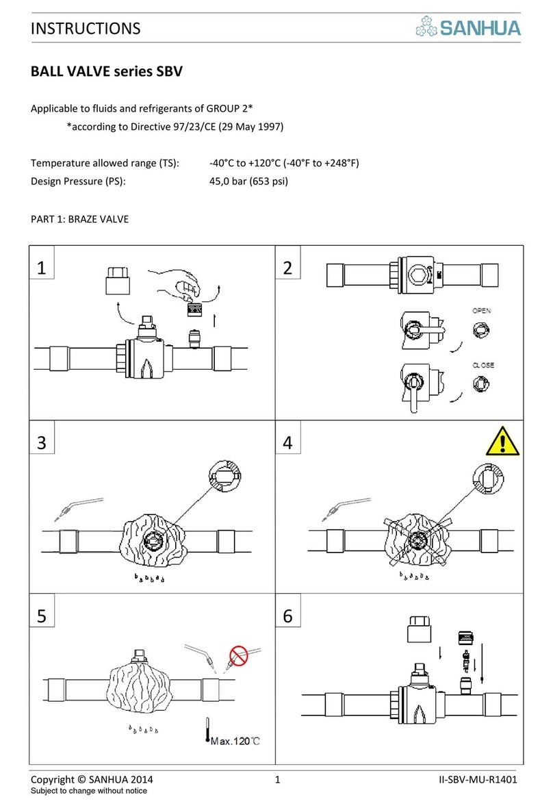
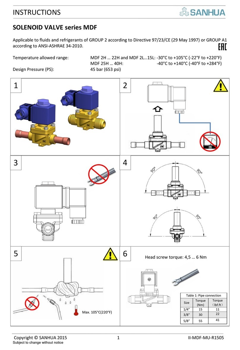
SOLDER VERSION: Braze
inlet, outlet and (if present)
external equalization
connections of TEV using
specific alloy (SilFos 15).
Use a wet rag on the valve
during the brazing process
VERSION A BRASER: Braser les
connections d’entrée, de
sortie et (si présent)
d’égalisation externe en
utilisant un alliage spécifique
(type SilFos 15). Placer un
chiffon mouillé sur le corps de
la vanne pendant le brasage.
LÖTVERSION: Eingang, Ausgang
und (falls vorhanden) externen
Ausgleich einlöten unter
Verwendung spezieller
Legierung (SilFos 15). Während
des Lötvorgangs das Ventil mit
nassem Lappen umwickeln.
VERSIONE A SALDARE:
Brasare le connessioni di
ingresso, uscita e (se
presente) di
equalizzazione usando una
lega specifica (SilFos 15).
Usare uno straccio
bagnato sulla valvola
durante il processo di
brasatura.
VERSION SOLDAR: Soldar
las conexiones de
entrada, salida y (si
presente) de la igualación
usando una aleación
específica (SilFos 15).
Poner un paño húmedo
encima de la válvula
durante el proceso de
soldadura.
3a
Respect the correct
installing position in the
plant admitted for the
thermostatic expansion
valve (TEV). Evaporators
with liquid distributors
need TEV with external
equalization
Positionner correctement la
vanne d’expansion
thermostatique dans
l’installation. Les évaporateurs
avec distributeurs ont besoin
de TEV avec égalisation
externe
Korrekte Einbaulage des
thermostatischen
Expansionsventiles (TEV)
innerhalb der Anlage beachten.
Verdampfer mit
Flüssigkeitsverteiler benötigen
TEV mit externem
Druckausgleich
Rispettare la corretta
posizione di installazione
nell’impianto ammessa
per la valvola di
espansione termostatica
(TEV). Gli evaporatori con
distributore di liquido
necessitano di una TEV
con equalizzazione esterna
Respetar la posición
correcta de instalación
en el equipo admitido
por la válvula de
expansión termostática
(TEV). Los evaporadores
con distribuidor de
líquido necesitan una TEV
con igualación externa
3b
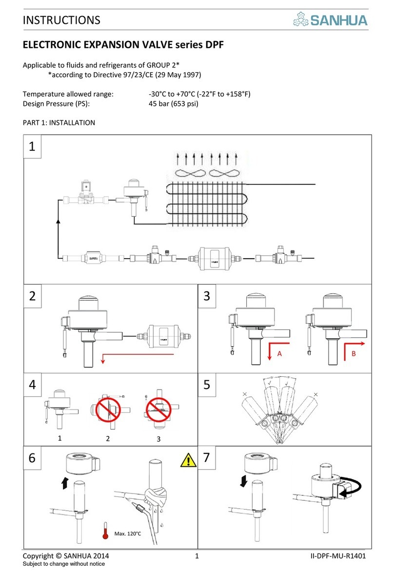
Install the bulb on the
suction line according to
the position shown in the
picture. Respect the
minimum length L (vertical
distance between the valve
and the liquid distributor).
It must be L > 7 x D (D= pipe
diameter). Install the bulbe
close to the evaporator
(from 3 to 6 in.)
Installer le bulbe sur la ligne
d’aspiration selon la position
indiquée sur le schéma.
Respecter la distance
minimum L (distance verticale
entre la vanne et le
distributeur). Elle doit
respecter la règle L > 7xD (où
D est le diamètre du tube
cuivre). Installer le bulbe près
de l’évaporateur (de 3 à 6
pouces)
Thermofühler gemäß Bild an
der Saugleitung befestigen.
Minimalen Abstand L einhalten
(vertikaler Abstand zwischen
Ventil und Flüssigkeitsverteiler).
Es muss L > 7 x D (D=
Rohrdurchmesser) eingehalten
werden. Den Fühler nahe am
Verdampfer montieren (von 3
bis 6 in.; von 75 bis 150mm)
Installare il bulbo sulla
linea di aspirazione
secondo la posizione
mostrata in figura.
Rispettare la lunghezza
minima L (distanza
verticale fra la valvola e il
distributore di liquido).
Deve essere
L > 7 x D (D= diametro del
tubo). Installare il bulbo
vicino all’evaporatore (da
3 a 6 pollici)
Instalar el bulbo en la
línea de aspiración según
la posición mostrada en
la figura. Respetar la
longitud mínima L
(Distancia vertical entre
la válvula y el distribuidor
de líquido). Debe ser
L>7 x D(D= diámetro) del
tubo). Poner el tubo
cerca de la salida del
evaporador ( de 3 a 6
pulgadas)
4
Fix the bulb on the pipe
(suction line) using a clamp
as shown in the picture
Fixer le bulbe sur la ligne
d’aspiration en utilisant un
collier comme montré sur le
schéma
Thermofühler mit einer Schelle
gemäß Bild am
Saugleitungsrohr befestigen.
Fissare il bulbo sul tubo
della linea di aspirazione
usando un morsetto come
in figura
Fijar el bulbo en el tubo
de la línea de aspiración
usando una abrazadera
como en la figura.
5
After the TEV installation,
check that: the evaporator
inlet temperature (t2) must
be bigger than the
evaporator outlet
temperature (t1 =
temperature measured by
the bulb)
Après avoir installé la vanne,
vérifier que la température
d’entrée de l’évaporateur (t2)
est supérieure à la
température de sortie de
l’évaporateur (t1 mesurée par
le bulbe)
Nach Installation des TEV
sicherstellen, dass die
Verdampfereintrittstemperatur
(t2) höher ist als die
Verdampferaustrittstemperatur
(t1 = vom Fühler gemessene
Temperatur).
Dopo l’installazione della
TEV controllare che: la
temperatura di ingresso
all’evaporatore (t2) deve
essere maggiore della
temperatura di uscita
dall’evaporatore (t1 =
temperatura misurata dal
bulbo)
Después de la instalación
de la TEV, comprobar
que: la temperatura de la
entrada al evaporador
(t2) ha de ser mayor que
la temperatura de
salida(t1=temperatura
medida por el bulbo).
6a
Factory presetting of TEV
(with or without MOP) is
just provided on standard
products. It is possible to
customize the superheat
value (Tsh ) setting:
Le préréglage d’usine des TEV
(avec ou sans MOP) est
uniquement effectué sur les
composants standards. Il est
possible de personnaliser la
valeur de désurchauffe (Tsh)
Werkseinstellung von TEV (mit
oder ohne MOP) wird nur bei
Standardprodukten
vorgenommen.
Kundenspezifische Einstellung
der Überhitzung (Tsh) ist
möglich :
Nei prodotti standard è
fornito un pre-settaggio di
fabbrica della TEV (con o
senza MOP). E’ possibile
personalizzare il settaggio
del surriscaldamento
Tsh:
El producto estándar de
la TEV ( con o sin MOP)
lleva un ajuste de fábrica.
Es posible personalizar el
ajuste del
supercalentamiento
Tsh:
6b
Using a screwdriver turn in
counterclockwise the
regulation screw until the
stop position.
A l’aide d’un tournevis,
tourner dans le sens inverse
des aiguilles d’une montre la
vis de régulation jusqu’à la
butée.
Mit einem Schraubendreher die
Einstellschraube gegen den
Uhrzeigersinn bis zum Anschlag
drehen.
Usando un cacciavite
girare in senso antiorario
la vite di regolazione fino
alla posizione di stop.
Con un destornillador
girar en sentido contrario
del reloj el tronillo de
regulación hasta la
posición de fin.
7
Turn the regulation screw
in clockwise until the
desired Tsh value (see
table 1 for details)
Tourner la vis de régulation
dans le sens des aiguilles
d’une montre jusqu’à la valeur
désirée (Tsh). Se référer à la
table 1 pour les détails.
Die Einstellschraube im
Uhrzeigersinn drehen, bis die
gewünschte Überhitzung Tsh
erreicht wird (Siehe Tab.1 für
Details)
Girare in senso orario la
vite di regolazione fino al
raggiungimento del valore
richiesto di Tsh (vedi
tabella 1 per dettagli)
Girar el tornillo de
regulación en el sentido
del reloj hasta el valor
deseado (ver Tabla 1
para detalles) del Tsh
