5
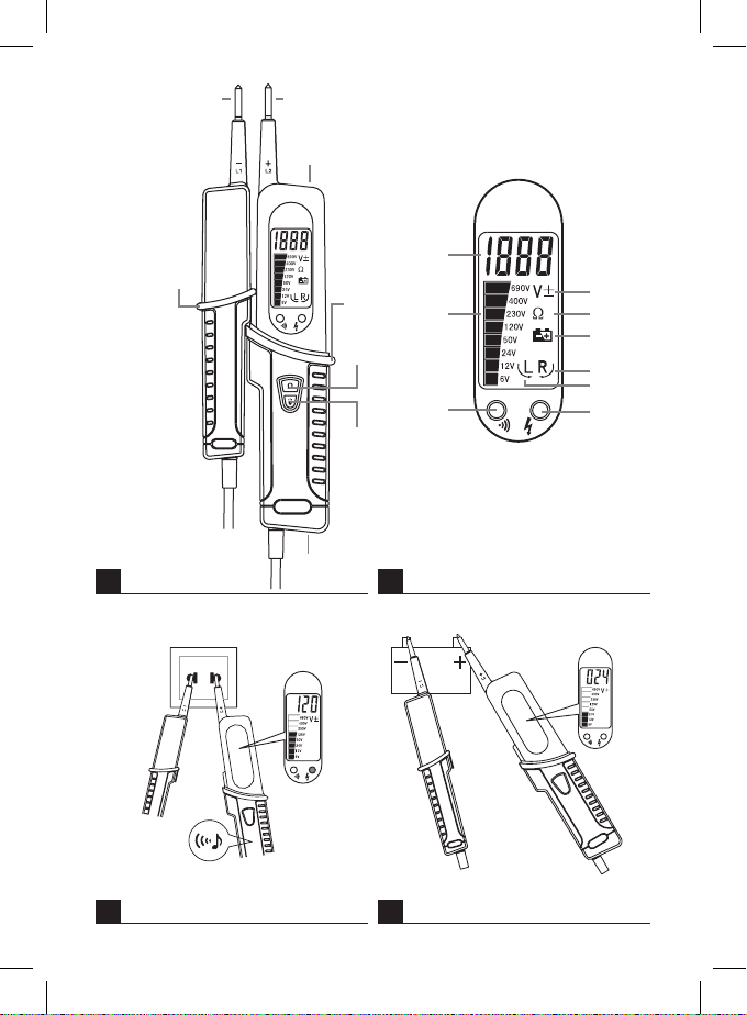
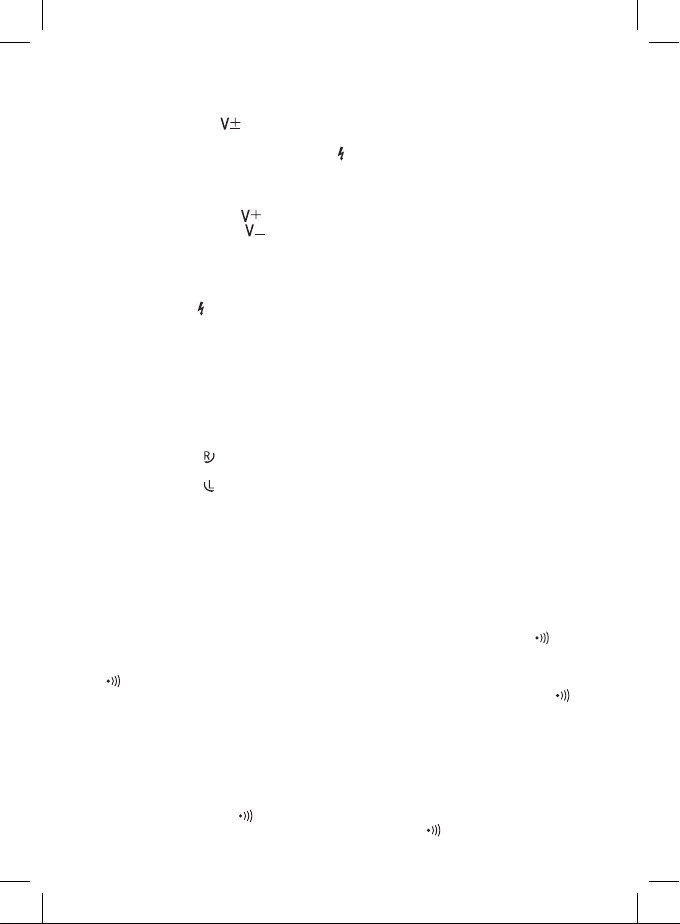
AC Voltage Value Indication
Place both measuring tips onto the measured object (circuit).
The voltage value will appear on the analogue scale/digital screen.
The screen will display the icon, you will hear a buzzer and the tester‘s LED will light up.
(see Fig. 3)
Note: If batteries are not inserted, the buzzer and the LED will not be functional.
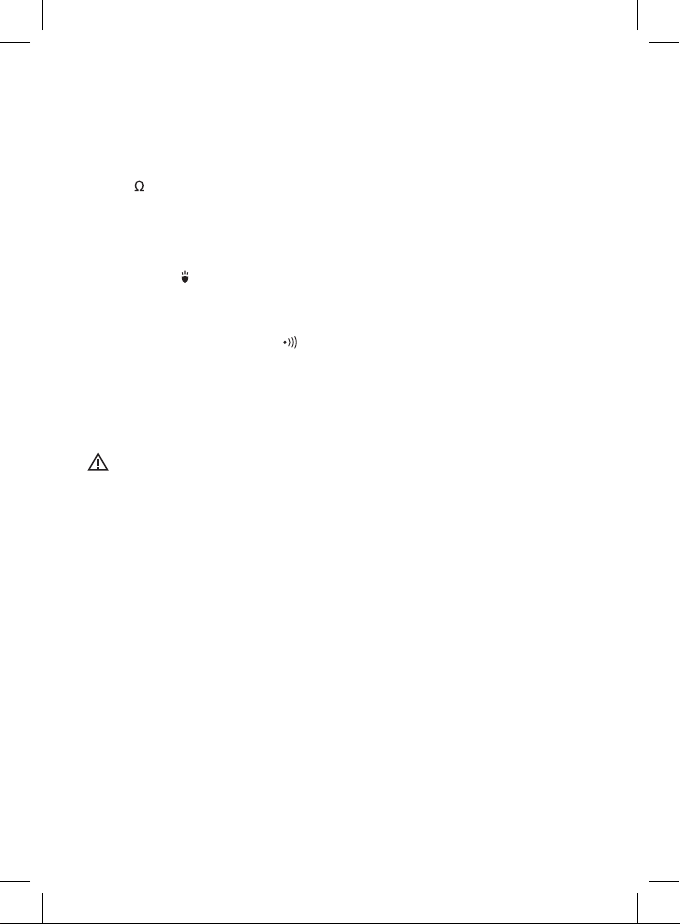
DC Voltage Value Indication
Place both measuring tips onto the measured object (circuit).
The voltage value will appear on the analogue scale/digital screen.
If L2 tip is on the positive pole, icon will appear.
If L2 tip is on the negative pole, icon will appear and you will hear a buzzer.
(see Fig. 4)
Note: If batteries are not inserted, the buzzer will not be functional.
Identifying the Phase Conductor
Place measuring tip L1 or L2 onto the phase conductor. If phase voltage is higher than 100 V, you will
hear a buzzer and the LED will light up.
While measuring, grip the tester with tip L2 rmly to increase sensitivity of measurement.
Your nger or palm must be in zone A (see Fig. 5).
Note:
If batteries are not inserted, phase detection will not be functional.
Before measuring, run a test on a dierent, known phase conductor.
After measuring, test the circuit again using both tips.
The measurement results may be negatively aected by electrostatic elds, level of insulation, etc.
Determining Phase Sequence
Place tip L1 onto the assumed L1 phase and L2 onto the assumed L2 phase.
If the screen shows the icon, the phase sequence is clockwise.
(see Fig. 6)
If the screen shows the icon, the phase sequence is counter-clockwise.
In that case, you should switch the tips and make the measurement again.
(see Fig. 7)
Note:
Phase sequence detection is functional at voltages higher than 100 V AC.
Before measuring, run a test measurement on a dierent, known three-phase source.
When measuring, make sure the tips are in solid contact with the measured source.
While measuring, grip the tester with tip L2 rmly to increase sensitivity of detection.
Continuity Test
Connect measuring tips L1 and L2 to the circuit you wish to measure.
If resistance of the measured circuit is lower than 200 kΩ, you will hear a buzzer and the LED will
light up.
If resistance of the measured circuit is between 200 kΩ and 500 kΩ, the buzzer may/may not sound and
the LED may/may not light up.
If resistance of the measured circuit is higher than 500 kΩ, the buzzer will not sound and the LED
will not light up.
Note:
If batteries are not inserted, continuity testing will not be functional.
Before testing, disconnect all power supply from the circuit you wish to test and thoroughly discharge all
capacitors.
Diode Test
Connect tip L1 to the diode‘s cathode and tip L2 to the diode‘s anode.
You will hear a buzzer and the LED will light up.
Switch the connection of the tips; the buzzer will not sound and the LED will not light up.