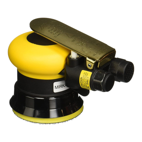
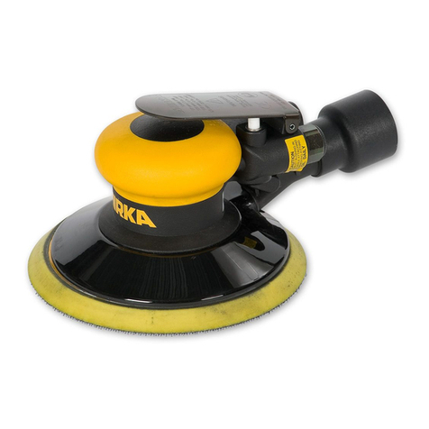
MIRKA MR-312TH User manual

Two-handed Rotary Polisher
77 mm (3 in.) & 125 mm (5 in.)
English Operating Instructions 1–10
Deutsch Betriebsanleitung 11–20
Français Notice d´utilisation 21–30
Italiano Istruzioni sull´uso 31–40
Svensk Bruksanvisning 41–50
Suomi Käyttöohje 51–60
Español Instrucciones de manejo 61–70
Nederlands Gebruiksaanwijzing 71–80
Русский Руководство по эксплуатации 81–90
Português Instruções de uso 91–100
Eesti Kasutusjuhend 101–110
English Operating Instructions 1-10
Deutsch Betriebsanleitung 11-17
Français Notice d´utilisation 19-25
Italiano Istruzioni sull´uso 27-33
Svensk Bruksanvisning 35-41
Norsk Brugsanvisning 43-49
Dansk Brugsanvisning 51-57
Suomi Käyttöohje 59-65
Español Instrucciones de manejo 67-73
Nederlands Gebruiksaanwijzing 75-81
Русский Руководствопоэксплуатации 83-89
Português Instruções de uso 91-97
Eesti Kasutusjuhend 99-105

1
Parts Page
RAG 02/05/09 MDR 02/17/09
THE PARTS PAGE WAS NOT REDESIGNED
1
LO
R
TN
O
CD
E
EP
S™DNA
H
o
w
T
38
10
BPX5
6
1G
NIR
G
N
I
N
IATER
LA
N
RE
T
N
I9300APX66
-DUE TO ADDING 77mm (3 in.) MACH INE,
B
RAG 11/12/08 PWH 11/13/08
-RELEASE FOR PRODUCTION
A
DESCRIPTION / DATE
R
REVISION RECORD
T
P
O
A
KR
IM-E
LDN
AH
ED
I
S
67 XPA1981
Y
TQ
NO
I
T
P
I
R
C
SE
D
N
/
P
TI
1
Y
LB
M
E
S
S
ARE
C
AP
S
R
O
T
O
M
m
m
0.
0
2
79
2
1
A
P
X
1
1GN
IR
G
N
I
N
IA
TER
LANRETXE
04
00AP
X2
1SD
LE
IH
S
2
-
G
N
I
R
AE
B
8
X
62
X
01
12
00A
P
X3
1ETALPDNERAE
R
7
100BP
X
4
1
R
OT
O
RD
E
N
I
H
C
A
M
5
00
0
B
P
X
5
5
EN
A
V
0
1
0
0
A
P
X
6
1
R
O
T
ORD
E
NI
H
C
AM
R
OTOMmm6
3
x
m
m
0
.
05
Ø
8
1
1
0BP
X7
5
R
O
TO
Mm
m
0
.
63x
m
m
0
.
05
Ø
R
O
F
E
NA
V
5
44
0
A
P
X8
3
Y
E
K
F
F
U
R
D
O
O
W
m
m
3
1
xm
m
3
1
4
0
0
A
P
X
9
1
Y
LB
M
E
SS
A
R
E
DNI
L
Y
C
m
m
0
.6
3
X
m
m
0.
0
5
Ø
1
4
40A
P
X0
1
2
G
N
I
R
-
O
m
m
0
.
2
x
m
m
5
24
00
A
PX1
1
1Y
L
BM
E
S
S
A
R
E
D
N
I
L
YC
5
0
0
0
A
P
X2
1
1E
T
A
L
PD
N
E
T
NOR
F
6
1
0
0
B
P
X3
1
1S
D
L
EI
H
S
2-G
N
I
R
A
E
B
8
X
82
X
21
9
1
00A
P
X4
1
1RO
T
OMm
m0
.
02
D
N
A
H
2
-Y
L
BM
E
S
S
A
TF
A
H
SRO
T
O
M
9
92
1
A
P
X5
1
1R
E
C
A
PS
R
OT
OMmm
0
.
0
2
59
21A
P
X6
1
1R
O
T
O
M
m
m0.
6
3
-YL
B
M
E
S
S
A
T
FA
H
S
R
OT
O
M
0
0
31
A
P
X7
1
3
R
A
E
G
T
E
N
AL
P
2
5
1
0
A
P
X8
1
3
G
NIR
A
E
BE
L
D
EE
N7
x
3
x
5
4
2
2
0
A
P
X9
1
1R
AE
G
G
NI
R
1
5
1
0A
P
X02
1
G
N
I
R
-
Om
m
1.
3
xmm
4.
9
3
5
40
0
A
P
X12
1
G
N
IS
UO
HELDN
IPS
DENIH
CAM
0
6
00BPX
2
2
1
)B2
-
C
N
U
02
-4
/
1
(
Y
L
B
M
E
S
S
A
E
L
D
NI
P
S
Y
R
A
T
E
N
A
L
P
6
5
4
0
A
P
X3
2
1
Y
L
B
M
E
S
SA
E
L
D
N
IP
S
Y
R
A
TE
N
A
LP
0
31
0A
P
X42
1
SDL
E
I
H
S
/S
LAE
S
O
N
-
GN
I
R
AE
B
5
x4
2x
517
4
10
A
P
X
5
2
1
K
H
T
0
1.
0xD
O
5
.
32
x
D
I
0
.02
,
R
ECA
PS
3120APX6
2
1LAES1-
G
N
IRAEB
5
x
42
x
5
1
8
4
10APX72
1
G
N
I
RG
N
I
N
IA
TE
R
m
m3
.41
0
1
1
0A
PX8
2
1
G
N
I
RGN
I
N
IATER
M
M
8
.32
7
110APX92
2G
U
L
PD
E
D
AE
R
H
T
8
M
1
1
7
1
A
P
X03
31 XPB0401 36.0 mm RH NV PMS 123 YELLOW MIRKA HOUSING W/SIDE HANDLE HOLE 1
1
)
sen
i
h
caM
MP
R000
,01rof(
T
RESNI
REL
F
F
U
M
2300APX23
1
LAES
G
NISU
OHPO
T
8121APX33
1
L
AE
S
G
N
ISU
O
H
RE
W
OLVN
5
5
2
1A
PX43
1
G
N
I
REVI
T
PA
C
TE
L
N
I
0
15
0
A
P
X5
3
1
G
N
I
R
-
Omm
87
.
1xm
m
6
.
7
9
05
0
A
P
X6
3
1
)
s
e
n
i
h
c
aM
V
C&
V
N
(G
N
I
R
-
O
8
2
6
0
A
P
X73
2R
E
L
F
FUM
6
7
7
0
A
PX8
3
39 XPA0731 INLET/EXHAUST END CAP ASSEMBLY FOR NV MACHINES 1
1Y
L
B
M
E
S
S
AG
N
I
H
S
UB
T
E
LNIT
P
N8
1
-
4
/
1
3
1
0
0
A
P
X0
4
4
KC
A
L
Bm
m
5
1
X0
.
4
M
X
RO
TD
A
EH
N
O
T
T
UB
,
W
ER
C
S
8
9
3
1
A
P
X14
TP
O
G
NI
R
R
E
CA
P
S
56
81A
PX2
4
TP
O
K
C
A
L
B
-
R
E
G
NAH0
2
4
0
B
P
X3
4
44 XPB0356 36.0 mm DIE-CAST MACHINE MOTOR HOUSING W/SIDE HANDLE
MOUNTING STUDS 1
1N
I
P
G
N
IR
PSRE
DN
I
L
YC
4
0
0
0A
P
X5
4
1
E
V
E
E
L
S
EVL
A
V
5
1
0
0
A
P
X64
1YLBMESSA
ME
TSEVLAV
5560APX74
48 XPA2070 MIRKA 3,000 RPM BUFFER/SANDER THROTTLE LEVER - TwoHAND 1
1
T
A
E
S
EV
L
A
V
9
0
0
0
A
P
X94
1
E
VL
A
V
7
0
0
0A
P
X0
5
1
G
NI
R
P
S
E
V
L
A
V
4
1
00
A
P
X1
5
1
Y
L
B
M
E
S
S
A
L
A
E
S
E
N
I
L
R
I
A0
3
70
A
P
X2
5
1
T
E
K
S
A
G
T
SU
A
HX
E
0
0
5
0
A
P
X3
5
1
E
L
ZZ
O
N
T
S
U
A
H
XE
V
C
/
V
N
2
8
1
0
B
P
X4
5
3
W
ER
CS
P
A
CD
A
E
H
N
O
T
TUBTE
KC
O
S
X
E
H
8
X
4M
4
6
6
0
A
PX5
5
1)
seni
h
c
a
M
V
C
&
V
N(
G
NI
BU
T
T
SU
A
H
XE
71
50A
PX6
5
1
P
MA
L
C
GN
I
B
U
T
61
50A
PX7
5
1G
N
I
BU
T
T
E
L
NI
1
1
5
0
A
P
X85
1
DU
ORH
S
R
EFFU
B
8
2
2
0C
PX9
5
1
HC
N
ER
Wm
m
3
1
5
4
1
0
A
P
X06
61 NA 1 Back-Up Pad supplied with each tool (type determined by model) 1
61 N/A 1 Back-up Pad supplied with each tool (type determined by model) 1
62 XPB0402 36.0 mm LH NV PMS 123 YELLOW HOUSING W/SIDE HANDLE HOLE 1
7
K
C
A
L
Bmm
0
3
X0
.
4
MX
R
O
TD
A
E
H
N
O
T
T
U
B
,
W
ER
C
S
0
3
4
1
A
P
X3
6
1G
NI
R
-
O
mm
5.
1
x
m
m9
3
4
0
0
A
P
X4
6
ITEM NO. TORQUE SETTINGS N-m (in.-lbs)
22 6.2 - 7.3 (55 - 65)
40 6.8 - 8.1 (60 - 72)
41 3.0 - 3.4 (27 - 30)
55 2.4 - 3.4 (21 - 30)
63 3.3 - 3.7 (29 - 33)
XX/XX +/-
TOOLS INC.
RAG 11/13/08
PRECISION
XPD0060
NA
NA
0.05
P/N
TITLE
DRWN BY / DATE
MATERIAL
.XX +/-
DUCTION IN PART OR AS A WHO LE WITHOUT THE WRITTEN
PROPRIETARY AND CONFIDENTIAL
0.5°
X'POLE
11/12/08
NA
PROPERTY OF X'PO LE PRECISION TOOLS INC. ANY REPRO-
ANGLES +/-
0.1
PERMISSION OF X'POLE PREC ISION TOOLS INC. IS PROHIBITED.
CKD BY / DATE ENG APP / DATE
STD TOL
.X +/-
PWH
THE INFORMATION CONTAINE DIN T HISD RAWING IS THE SOLE
.XXX +/-
Mirka 77 & 125 mm (3 & 5 in.) 3 ,000 RPM
TwoHAND™ BUFFER/SA NDER PARTS PAGE
125mm (5 in.)
15
125mm (5 in.)
23
125mm (5 in.)
77mm (3 in.)
2
3
4
52
7
8
55
10
11
13
14
17
18
19 20
21
22
24
25
26
27
28
29
30
31
32
33
34 35
36
37
39
40
42
43
44
45
47
46
49
9
16
38
41
63
57
58
50
51 56
48
59
60
61
53
54
62 41
64
30
67
66
12
65
41
1
5
6
9
11
63
61
77mm (3 in.)
77mm (3 in.)
Original Instructions
F
E
C
A
H
G
D
B
D

2
Parts List
Item P/N Description Qty.
1 MPA1297 MOTOR SPACER ASSEMBLY (77 mm [3 in.] Machines only) 1
2 MPA0040 RETAINING RING 1
3 MPA0021 BEARING 1
4 MPB0017 REAR ENDPLATE 1
5 MPB0005 ROTOR (77 mm [3 in.] Machines only) 1
6 MPA0010 VANE (77 mm [3 in.] Machines only) 5
7 MPB0118 ROTOR (125 mm [5 in.] Machines only) 1
8 MPA0445 VANE (125 mm [5 in.] Machines only) 5
9 MPA0041 WOODRUFF KEY 3
10 MPA0441 CYLINDER ASSEMBLY (125 mm [5 in.] Machines only) 1
11 MPA0042 O-RING 2
12 MPA0005 CYLINDER ASSEMBLY (77 mm [3 in.] Machines only) 1
13 MPB0016 FRONT ENDPLATE 1
14 MPA0019 BEARING 1
15 MPA1299 MOTOR SHAFT ASSEMBLY (77 mm [3 in.] Machines only) 1
16 MPA1295 MOTOR SPACER (77 mm (3 in.) Machines only) 1
17 MPA1300 MOTOR SHAFT ASSEMBLY (125 mm [5 in.] Machines only) 1
18 MPA0152 PLANET GEAR 3
19 MPA0224 NEEDLE BEARING 3
20 MPA0151 RING GEAR 1
21 MPA0045 O-RING 1
22 MPB0060 SPINDLE HOUSING 1
23 MPA0456 PLANETARY SPINDLE ASSEMBLY 1/4-20 UNC-2B (77 mm [3 in.] Machines only) 1
24 MPA0130 PLANETARY SPINDLE ASSEMBLY 5/16-24 UNF-2B (125 mm [5 in.] Machines only) 1
25 MPA0147 BEARING 1
26 MPA0213 SPACER 1
27 MPA0148 BEARING 1
28 MPA0110 RETAINING RING 1
29 MPA0117 RETAINING RING 1
30 MPA1711 THREADED PLUG 2
31 MPB0401 RH NV HOUSING 1
32 MPA0032 MUFFLER 1
33 MPA1218 TOP HOUSING SEAL 1
34 MPA1255 NV LOWER HOUSING SEAL 1
35 MPA0510 INLET CAPTIVE RING 1
36 MPA0509 O-RING 1
37 MPA0628 O-RING 1
38 MPA0776 MUFFLER 2
39 MPA0731 INLET/EXHAUST END CAP ASSEMBLY 1
40 MPA0013 INLET BUSHING ASSEMBLY 1
41 MPA1398 SCREW, BLACK 4
42 MPA1865 SPACER RING 2
43 MPB0420 HANGER - BLACK 1
44 MPB0356 MOTOR HOUSING 1
45 MPA0004 SPRING PIN 1
46 MPA0015 VALVE SLEEVE 1
47 MPA0655 VALVE STEM ASSEMBLY 1
48 MPA2070 POLISHER THROTTLE LEVER 1
49 MPA0009 VALVE SEAT 1
50 MPA0007 VALVE 1
51 MPA0014 VALVE SPRING 1
52 MPA0730 AIRLINE SEAL ASSEMBLY 1
53 MPA0500 EXHAUST GASKET 1
54 MPB0182 NV/CV EXHAUST NOZZLE 1
55 MPA0664 SCREW 3
56 MPA0517 EXHAUST TUBING 1
57 MPA0516 TUBING CLAMP 1
58 MPA0511 INLET TUBING 1
59 MPC0228 POLISHER SHROUD 1
60 MPA0145 13 mm WRENCH 1
61 NA 1 Back-Up Pad supplied with each tool (type determined by model) 1
62 MPB0402 LH NV HOUSING 1
63 MPA1430 SCREW, BLACK 7
64 MPA0043 O-RING 1
65 MPB0183 SPEED CONTROL 1
66 MPA0039 RETAINING RING 1
67 MPA1981 SIDE HANDLE 1

3
Polisher Spare Parts Kits
GMPA0994 Cylinder and O-Ring Kit
Code: 8993009211
FMPA2220 Rotor, Vanes and Key Kit
Code: 8994020611
RAG 01/31/08 PWH 02/13/08
-RELEASE FOR PRODUCTION
A
DESCRIPTION / DATE
R
REVISION RECORD
Y
T
Q
N
O
ITPIRCSEDN/PTI
2Y
E
KFFURDOOWmm
31
xm
m
3
1400
APX1
1
R
O
T
O
RDENIHCAMR
O
TOM
m
m63xm
m
0.0
5
Ø8
1
10BPX2
5
ROT
O
Mm
m
0
.
6
3
x
mm0.05
Ø
ROFEN
A
V5
4
40APX3
4 XPA1887 LABEL FOR AirVANTAGE ROTOR, VANES AND KEYS KIT - 36.0 MM MOTOR 1
1
G
ABEP
AN5
01/31/08
PWH
02/13/08
REVISED 12/19
KEYS KIT - 36.0 MM MOTOR
XPA1881
P/N
RAG
NA
NA
TITLE
DRWN BY / DATE
MATERIAL
PROPRIETARY AND CONFIDENTIAL
DUCTION IN PART OR AS A WHOLE WITHOUT THE WRITTEN
.XX +/-
PERMISSION OF X'POLE PRECISION TOOLS INC. IS PROHIBITED.
0.5°
X'POLE PRECISION
/05
PROPERTY OF X'POLE PRECISION TOOLS INC. ANY REPRO-
ANGLES +/-
0.1
0.05
CKD BY / DATE ENG APP / DATE
STD TOL
.X +/- XX/XX +/-
TOOLS INC.
THE INFORMATION CONTAINED IN THIS DRAWING IS THE SOLE
.XXX +/-
AirVANTAGE™ ROTOR, VANES AND
SEE BOM
AMPA221412,000RPMMuferKit
Code: 8994026011 CMPA2216 Air Inlet Kit
Code: 8994024011
REVISION RECORD
R DESCRIPTION / DATE
A-RELEASE FOR PRODUCTION
RAG 01/30/08 PWH 02/13/08
Y
T
Q
N
O
ITPIRCSEDN/PTI
2RELFFUM6770APX1
1
)
sen
i
h
c
a
MMPR
000
,
0
1
r
of(TRESNIRE
L
FFUM230
0
APX2
1
TI
K
R
E
LFF
U
MMPR0
0
0,21EGATNAV
r
i
A
ROFLEBAL3881APX3
1G
ABEP
AN4
RAG
01/30/08
PWH
02/13/08
REVISED 12/19
- 2 HAND
XPA1877
TOOLS INC.
NA
0.05
P/N
TITLE
DRWN BY / DATE
MATERIAL
.XX +/-
DUCTION IN PART OR AS A WHOLE WITHOUT THE WRITTEN
PROPRIETARY AND CONFIDENTIAL
NA
0.5°
X'POLE PRECISION
/05
PROPERTY OF X'POLE PRECISION TOOLS INC. ANY REPRO-
ANGLES +/-
0.1
PERMISSION OF X'POLE PRECISION TOOLS INC. IS PROHIBITED.
CKD BY / DATE ENG APP / DATE
STD TOL
.X +/- XX/XX +/-
THE INFORMATION CONTAINED IN THIS DRAWING IS THE SOLE
.XXX +/-
AirVANTAGE™ 12,000 RPM MUFFLER KIT
SEE BOM
Scaled 50%
DMPA0799 Endplate Bearing Kit
Code: 8993019811 EMPA2218 Speed Control Kit
Code: 8994025511
HMPA0801 Rotor, Vanes and
Key Kit
Code: 8993017711
Scaled 50%
BMPA2226 Planetary Spindle
Bearing Kit
Code: 8994222711

4
MIRKA 3,000 RPM
77 mm (3 in.) & 125 mm (5 in.)
TWO-HANDED ROTARY POLISHER
The warranty terms are as follows:
- 12 months on KWH MIRKA air tools.
- 3 months on tool parts repaired by KWH MIRKA.
The warranty period commences at the date of purchase. The warranty only covers imputable material and manu-
facturing defects.
PartsreplacementorrepairduringthewarrantyperiodisfreeofchargeifcarriedoutbyanofcialKWHMIRKA
service center.
Freight costs are always to be paid by the purchaser.
The warranty does not include:
Normal wear and tear i.e.
- Bearings,backingpad,shroud,rotor,vanes,swiveltting,mufer
Overloading or improper use i.e.
- Dropping the tool in water
- Damage caused by misuse
- Damage caused by anything other than defects in material and workmanship
- Dropping or other excessive impact
Normal maintenance and service that can be carried out by the operator:
- Changing of the packing pad
- Changing of the spindle bearing
- Changingoftheexhausttting
- Changing of the shroud
Please Note! All other service operations must be carried out by an authorized Mirka service center.
The warranty only covers the local repair, not the tool replacement.
Compensation for downtime and loss of production are explicitly not included in the warranty.
Repair claims under warranty will only be honored if the tool is returned in its original assembled state. Any disas-
sembly will void the warranty.
The warranty can only be submitted to the dealers where the tool was purchased.
Warranty
Manufacturer/Supplier
KWH Mirka Ltd.
66850 Jeppo, Finland
Tel: + 358 20 760 2111
Fax: +358 20 760 2290
Required Personal Safety Equipment
Safety Glasses Breathing Masks
Safety Gloves Ear Protection
Recommended Airline
Size - Minimum
10 mm 3/8 in
Recommended Maximum
Hose Length
8 meters 25 feet
Air Pressure
Maximum Working Pressure 6.2 bar 90 psig
Recommended Minimum NA NA
Operator Instructions
Includes – Warranty, Please Read and Comply, Proper Use of
Tool, Work Stations, Putting the Tool Into Service, Operating
Instructions,ProductConguration/SpecicationsTables,
Parts Page, Parts List, Polisher Spare Parts Kits,
Trouble Shooting Guide, Service Instructions
Declaration of conformity
KWH Mirka Ltd.
66850 Jeppo, Finland
declare on our sole responsibility that the products
77mm(3in.)and125mm(5in.)3,000RPMRotaryPolisher(See“ProductConguration/Specications”Tablefor
particular Model) to which this declaration relates is in conformity with the following standard(s) or other normative document(s) EN ISO
15744:2008. Following the provisions of 89/392/EEC as amended by 91/368/EEC & 93/44/EEC 93/68/EEC Directives and consolidating
Directive 2006/42/EC
Place and date of issue Name Signature or equivalent marking of authorized person
Important
Read these instructions care-
fully before installing, operating,
servicing or repairing this tool.
Keep these instructions in a safe
accessible location.
Tom Nordström08.01.2010 Jeppo

5
1) General Industry Safety & Health Regulations, Part 1910,
OSHA 2206, available from: Superintendent of Documents;
GovernmentPrintingOfce;WashingtonDC20402
2) Safety Code for Portable Air Tools, ANSI B186.1 available from:
American National Standards Institute, Inc.; 1430 Broadway;
New York, New York 10018
3) State and Local Regulations.
Closed Loop Pipe System
Sloped in the direction of air flow
Drain Leg
Ball Valve
To Tool Station
Filter
Drain Valve
Regulator
Lubricator
Ball
Valve
Ball Valve Air Flow
Air Dryer
Air Compressor
and Tank
Air Hose
To Coupler
at or near Tool
Please Read and Comply with Putting the Tool into Service
Operating Instructions
Use a clean lubricated air supply that will give a measured air
pressure at the tool of 6.2 bar (90 psig) bar when the tool is run-
ning with the lever fully depressed. It is recommended to use an
approved 10 mm (3/8 in.) x 8 m (25 ft) maximum length airline. It
is recommended that the tool be connected to the air supply as
shown in Figure 1.
Do not connect the tool to the airline system without incorporating
an easy to reach and operate air shut off valve. The air supply
shouldbelubricated.Itisstronglyrecommendedthatanairlter,
regulator and lubricator (FRL) be used as shown in Figure 1 as
this will supply clean, lubricated air at the correct pressure to
the tool. Details of such equipment can be obtained from your
supplier. If such equipment is not used then the tool should be
manually lubricated
To manually lubricate the tool, disconnect the airline and put 2 to
3 drops of suitable pneumatic motor lubricating oil such as Fuji
Kosan FK-20, Mobil ALMO 525 or Shell TORCULA® 32 into the
hose end (inlet) of the machine. Reconnect tool to the air supply
and run tool slowly for a few seconds to allow air to circulate the
oil. If the tool is used frequently, lubricate it on a daily basis or
lubricate it if the tool starts to slow or lose power.
It is recommended that the air pressure at the tool is 6.2 bar (90
psig) while the tool is running. The tool can run at lower pressures
but never higher than 6.2 bar (90 psig).
Work Stations
Proper Use of Tool
This polisher is designed for use all types of materials i.e. met-
als, wood, stone, plastics, etc. using abrasive designed for this
purpose. Do not use this polisher for any other purpose than that
speciedwithoutconsultingthemanufacturerorthemanufac-
turer’s authorized supplier. Do not use back-up pads that have a
working speed less than 3,000 RPM free speed.
The tool is intended to be operated as a hand held tool. It is
always recommended that the tool be used when standing on a
solidoor.Itcanbeinanypositionbutbeforeanysuchuse,the
operatormustbeinasecurepositionhavingarmgripandfoot-
ing and be aware that the polisher can develop a torque reaction.
Seethesection“OperatingInstructions”.
1) Read all instructions before using this tool. All operators must be fully trained in its
use and aware of these safety rules. All service and repair must be carried out by
trained personnel.
2) Make sure the tool is disconnected from the air supply. Select a suitable abrasive
and secure it to the back-up pad. Be careful and center the abrasive on the back-
up pad.
3) Always wear required safety equipment when using this tool.
4) When sanding always place the tool on the work then
start the tool. Always remove the tool from the work
before stopping. This will prevent gouging of the work
due to excess speed of the abrasive.
5)Alwaysremovetheairsupplytothepolisherbeforet-
ting, adjusting or removing the abrasive or back-up pad.
6)Alwaysadoptarmfootingand/orpositionandbeaware
of torque reaction developed by the polisher.
7) Use only correct spare parts.
8)Alwaysensurethatthematerialtobesandedisrmly
xedtopreventitsmovement.
9)Checkhoseandttingsregularlyforwear.Donotcarry
the tool by its hose; always be careful to prevent the tool
from being started when carrying the tool with the air
supply connected.
10) Do not exceed maximum recommended air pressure.
Use safety equipment as recommended.
11) The tool is not electrically insulated. Do not use where
there is a possibility of coming into contact with live
electricity, gas pipes, water pipes, etc. Check the area
of operation before operation.
12) Take care to avoid entanglement with the moving parts
of the tool with clothing, ties, hair, cleaning rags, etc. If
entangled, it will cause the body to be pulled towards
the work and moving parts of the machine and can be very dangerous.
13) Keep hands clear of the spinning pad during use.
14) If the tool appears to malfunction, remove from use immediately and arrange for
service and repair.
15) Do not allow the tool to free speed without taking precautions to protect any
persons or objects from the loss of the abrasive or pad.

6
Vacuum Type
Pad
Size mm
(inch)
Model
Number
Product Net
Weight kg
(pounds)
Height mm
(inch)
Length mm
(inch)
*Noise
Level
dBA
Power
watts
(HP)
Air Consumption
LPM (scfm)
*Vibration
Level
m/s2
*Uncertainty
K
m/s2
Non-Vacuum 77 (3) MR-30TH 0,96 (2,1) 113,6 (4,47) 245,9 (9,68) 85 343 (0,46) 594 (21) 1,2 0,6
125 (5) MR-50TH 1,02 (2,3) 113,9 (4,48) 271,0 (10,67) 88 343 (0,46) 594 (21) 1,3 0,7
Specifications subject to change without prior notice.
*The values stated in the table are from laboratory testing in conformity with stated codes and standards and are not sufficient for risk
evaluation. Values measured in a particular work place may be higher than the declared values. The actual exposure values and amount
of risk or harm experienced to an individual is unique to each situation and depends upon the surrounding environment, the way in which
the individual works, the particular material being worked, work station design as well as upon the exposure time and the physical condi-
tion of the user.KWH Mirka, Ltd. cannot be held responsible for the consequences of using declared values instead of actual exposure
values for any individual risk assessment.
Further occupational health and safety information can be obtained from the following websites:
http://europe.osha.eu.int (Europe)
http://www.osha.gov (USA)
Product Configuration/Specifications: 3,000 RPM Rotary Polisher

7
Symptom Possible Cause Solution
Low Power and/or Low Free
Speed
InsufcientAirPressure Check air line pressure at the Inlet of the Polisher
while the tool is running at free speed. It must be
6.2 Bar (90 psig/620 kPa).
CloggedMufer(s) Seethe“HousingDisassembly”sectionforMufer
removal. The Mufer can be back ushed with a
clean, suitable cleaning solution until all contami-
nates and obstructions have been removed. If the
Mufercannotbeproperlycleanedthenreplaceit.
ReplaceMuferInsert(Seethe
“HousingAssembly”Section).
Plugged Inlet Screen Clean the Inlet Screen with a clean, suitable
cleaning solution. If Screen does not come clean
replace it.
One or more Worn or Broken Vanes Install a complete set of new Vanes (all vanes must
be replaced for proper operation). Coat all vanes
with quality pneumatic tool oil. See “Motor Disas-
sembly”and“MotorAssembly”.
Internal air leakage in the Motor Housing
indicated by higher than normal air con-
sumption and lower than normal speed.
Check for proper Motor alignment and Lock Ring
engagement. Check for damaged O-Ring in Lock
Ring groove. Remove Motor Assembly and Re-In-
stalltheMotorAssembly.See“MotorDisassembly”
and“MotorAssembly”.
Motor Parts Worn Overhaul Motor. Contact authorized Mirka Service
Center.
Worn or broken Spindle Bearings Replace the worn or broken Bearings. See “Shaft
BalancerandSpindleDisassembly”and“Spindle
Bearings, AirSHIELD™ and Shaft Balancer As-
sembly”.
Air leakage through the Speed
Control and/or Valve Stem.
Dirty, broken or bent Valve Spring, Valve
or Valve Seat.
Disassemble, inspect and replace wore or dam-
aged parts. See Steps 14 and 15 in “Housing
Disassembly”andStep13in“HousingAssembly”.
Vibration/Rough Operation
Incorrect Pad Only use Pad Sizes and Weights designed for the
machine.
Addition of interface pad or other material Only use abrasive and/or interface designed for the
machine. Do not attach anything to the Polishers
Padfacethatwasnotspecicallydesignedtobe
used with the Pad and Polisher.
Improper lubrication or buildup of foreign
debris.
Disassemble the Polisher and clean in a suitable
cleaning solution. Assemble the Polisher. (See
“ServiceManual”)
Worn or broken Rear or Front Motor
Bearing(s)
Replace the worn or broken Bearings. See “Motor
Disassembly”and“MotorAssembly”.
Troubleshooting Guide
Note:AllSectionsreferredtounder“Solution”arelocatedattheendofthemanualin“ServiceInstructions”

8
MIRKA 3,000 RPM 77 mm (3 in.) &
125 mm (5 in.)
TWO-HANDED ROTARY POLISHER
SERVICE INSTRUCTIONS
NOTICE: To receive any expressed or implied warranty, tool must be repaired by an authorized Mirka Service Center. The following
general service instructions provided are for use after completion of the warranty period.
DISASSEMBLY INSTRUCTIONS
Motor Disassembly:
1. Remove the (61) Pad with the (60) 13 mm Wrench.
Take the T-6 Motor Lock Ring Wrench/Spindle Puller
(Included in MPA0928 Kit) and engage it into the tabs
of the (22) Spindle Housing. Rotate the T-6 Motor
Lock Ring Wrench/Spindle Puller counter-clockwise
until it disengages the Spindle Housing from the (44)
Motor Housing. Carefully lift the Spindle Housing up,
while at the same time watching to collect any of the
three (19) Needle Bearings or the three (18) Planet
Gears that may fall out. Remove any remaining Plan-
et Gears and Needle Bearings and set them aside.
Set the Spindle Housing assembly out-of-the-way.
2. For 77mm (3 in.) machines, remove the (16) Motor
Spacer from the (44) Motor Housing.
3. Grasp the Motor Assembly by the exposed end of the
(15 or 17) Motor Shaft and pull out the Motor Assem-
bly from the (44) Motor Housing and set it aside.
4. For 77mm (3 in.) machines, remove the (1) Motor
Spacer from the (44) Motor Housing.
5. Remove the (11) O-Ring from the (10 or 12) Cylinder.
Remove the (2) Retaining Ring from the (15 or 17)
Motor Shaft.
6. Remove the (4) Rear Endplate, (10 or 12) Cylinder, (5
or7)Rotorandve(6or8)Vanes.Thismayrequire
gripping the Rear Endplate with a Bearing Separator
(Included in MPA0928 Kit) and lightly pressing the (15
or 17) Motor Shaft through the (3) Bearing and Rear
Endplate. CAUTION: The (9) Key(s) will damage
the (13) Front Endplate if the Motor Shaft is pressed
throughwithoutremovingtheKey(s)rst.Remove
the Key(s) then press off the Front Endplate.
7. Remove the (3 and 14) Bearings from the (4 and 13)
Endplates using the T-8 Motor Faceplate Bearing
Removal Tool (Included in MPA0928 Kit). The end
of the tool with the larger diameter is for pressing the
(14) Bearing in the (13) Front Endplate out and the
smaller diameter end is for pressing the (3) Bearing in
the (4) Rear Endplate out.
Spindle Housing Disassembly:
1. Take the (22) Spindle Housing and with a small, thin-
tippedatheadscrewdriverpick-outtheslottedendof
the (29) Retaining Ring, then continue to peel-out the
Retaining Ring all the way around until it is free from
the groove in the Spindle Housing.
2. Screw the threaded end of the T-6 Motor Lock Ring
Wrench/Spindle Puller (Included in MPA0928 Kit)
into the (23 or 24) Planetary Spindle until hand tight.
NOTE: Make sure the (18) Planet Gears and (19)
Needle Bearings have been removed and set aside.
3. Remove the Planetary Spindle assembly. To ac-
complish this, create moderately sharp outward blows
to the Planetary Spindle, this can be done by taking
the cylindrical part of the T-6 Motor Lock Ring Wrench
(Included in MPA0928 Kit) and sliding it up the handle
away from the Planetary Shaft and hitting the washers
and set screw at the opposite end of the handle.
4. The (20) Ring Gear does not normally have to be
removed. If it is determined that it needs to be re-
placed, press it out from the same side the Planetary
Spindle Assembly is pressed in. Press it out by
pressing on the part of the gear teeth that is exposed
when looking in the bore from the (23 or 24) Planetary
Spindle side.
5.Withasmall,thin-tippedatheadscrewdriverpick-
out the slotted end of the (28) Retaining Ring, then
continue to peel-out the Retaining Ring all the way
around until it is free from the (23 or 24) Planetary
Spindle.
6. Use a Bearing Separator (Included in MPA0928 Kit) to
remove the (27) Bearing, (26) Shim and (25) Bearing
from the (23 or 24) Planetary Spindle.
Housing Disassembly:
1. Unscrew the threaded (30) Plug(s) and the (67) Side
Handle (if used) from the (44) Motor Housing.
2. Remove the (43) Hook and (42) Spacer Rings. (if
used)
3. Remove the (66) Retaining Ring. The (65) Speed
Control (with (64) O-Ring) will now pull straight out
from the (44) Motor Housing. Use an o-ring pick to
remove the O-Ring from the Speed Control.
4. Use a T-20 Torx® driver to unscrew all (41 and 63)
Screws.
5. Remove the (31 and 62) Housings.
6.Removethe(32)Muferand(33and34)Sealsfrom
the (31) Housing.
7. Remove the (39) End Cap.
8. Unscrew the (40) Inlet Bushing from the (39) End
Cap.Removethe(38)Mufers,(35)CaptiveRing,
and (36 and 37) O-Rings from the End Cap.
9. Remove the (56) Exhaust Tubing, (57) Tubing Clamp,
and (58) Inlet Tubing from the motor housing assem-
bly. Separate the Exhaust Tubing, Tubing Clamp, and
Inlet Tubing from each other.
10. Unscrew the three (55) Screws from the (44) Motor
Housing.
11. Remove the (54) NV/CV Exhaust Nozzle and the
(53) Gasket from the (44) Motor Housing.
12. Press out the (45) Spring Pin from the (44) Motor
Housing and remove the (48) Throttle Lever.
13. Remove the (52) Seal Assembly. This component
can become damaged during removal and will need
to be replaced if damaged.
14. Remove the (51) Spring, (50) Valve, (49) Valve Seat,
and the (47) Valve Stem from the (44) Motor Hous-
ing. Use an o-ring pick to remove the o-ring from the
Valve Stem.

9
15. Remove the (46) Sleeve from the (44) Motor Hous-
ing (if necessary).
16. Remove the (59) Shroud from the (44) Motor Hous-
ing.
ASSEMBLY INSTRUCTIONS
NOTE: All assembling must be done with clean dry
parts and all bearings are to be pressed in place by the
correct tools and procedures as outlined by the bearing
manufacturers.
Housing Assembly:
1.Pressthe(46)Sleeveushtothetopofthe(44)Mo-
tor Housing (if disassembled).
2. Lightly grease the o-ring and place it in the groove of
the (47) Valve Stem. Install the Valve Stem into the
(46) Sleeve.
3. Install the (49) Valve Seat, the (50) Valve and the (51)
Spring. Press the (52) Seal Assembly into the (44)
Motor Housing.
4. Install the (48) Throttle Lever into the (44) Motor
Housing with the (45) Spring Pin.
5. Install the (59) Shroud onto the (44) Motor Housing.
6. Install the (53) Gasket and the (54) NV/CV Exhaust
Nozzle using the three (55) Screws. Torque settings
to be 2.4 - 3.4 N-m (21 - 30 in-lbs). Insert the (56)
Exhaust Tubing and the (58) Inlet Tubing into the (57)
Tubing Clamp. Then insert the Exhaust Tubing into
the NV/CV Exhaust Nozzle and insert the Inlet Tubing
into the (52) Seal Assembly.
7.Installthetwo(38)Mufers,(36)O-Ring,(35)Captive
Ring, (37) O-Ring into the (39) End Cap. Lightly
grease the o-rings before installation.
8. Coat the threads of the (40) Inlet Bushing Assem-
bly with 1 or 2 drops of Loctite™ 222 or equivalent
non-permanent pipe thread sealant. Screw the Inlet
Bushing Assembly into the inlet port on the (39) End
Cap until hand tight. Torque settings to be 6.8 - 8.1
N-m (60 - 72 in-lbs).
9. Insert the (58) Inlet Tubing into the (35) Captive Ring.
Make sure that the Inlet Tubing is slide all the way
to the bottom of the hole. Air will leak out if the Inlet
Tubing is not slide all the way to bottom of the hole.
10.Installthe(32)Muferand(33and34)Sealsintothe
(31) Housing.
11. Install the internal housing components into the (31)
Housing. Then install the (62) Housing.
12. Install the Torx® (41 and 63) Screws. Torque setting
to be 3.0 - 3.4 N-m (27 - 30 in-lbs) for the 15 mm
long Screw. Torque setting to be 3.3 - 3.7 N-m (29
- 33 in-lbs) for the 30 mm long Screw.
13. Lightly grease the (64) O-Ring and place it in the
groove on the (65) Speed Control. Insert the Speed
Control into the (44) Motor Housing in the full on
position. Install the (66) Retaining Ring. Caution:
Make sure the Retaining Ring is completely snapped
into groove in the Motor Housing.
14. Install the (42) Spacer Rings into the (43) Hook. Se-
cure the hook by screwing in the (30) Plug(s) and/or
install the optional (67) Side Handle.
Planetary Spindle Assembly and Bearing Press Tool
Instructions:
1. Place the T-10A Spindle Bearing Pressing Tool Base
(IncludedinMPA0928Kit)ontoaat,cleansurface
of a small hand press or equivalent with the spindle
pocket facing upward. Place the (23 or 24) Spindle
Assembly into the spindle pocket by using its three
planetary gear shafts to align it with the three bores in
the Pressing Tool Base.
2. Place the (25) Bearing (no seals/shields) onto the
Spindle shaft. NOTE: Make sure that both the inner
and outer races of the Bearings are supported by the
Bearing Press Tool when pressing them into place.
Press the Bearing onto the shoulder of the Spindle
using the T-10B Spindle Bearing Press Tool Top
(Included in MPA0928 Kit) as shown in Figure .
3. Place the (26) Shim over the Spindle shaft and onto
the face of the (25) Bearing, making sure it is on cen-
ter. Press the (two seals) (27) Bearing down using
the T-10B Spindle Bearing Press Tool Top (Included in
MPA0928 Kit), being careful to make sure the Shim is
still centered on the vertical axis of the Spindle shaft
and Bearing. Secure the (28) Retaining Ring onto the
end of the Planetary Spindle Assembly.
4. If the (20) Ring Gear was removed, press it into the
(22) Spindle Housing until it rests on the shoulder.
5. Lightly press the entire Planetary Spindle Assembly
into the bore of the (22) Spindle Housing. Secure
the (29) Retaining Ring into the groove of the Spindle
Housing.
6. Place the three (19) Needle Bearings onto the plan-
etary shafts of the Planetary Spindle Assembly. Place
the three (18) Planet Gears onto the Needle Bearings.
Setthenishedassemblyasidebeingcarefultonot
let the Planetary Gears or Needle Bearings fall-out.
Press Tool Top
Press Tool Base
Bearing
Spindle
Bearing
Shim

10
Motor Assembly:
1.Presst(14)Bearing(2shields)intothe(13)Front
Endplate and (3) Bearing (2 shields) into the (4)Rear
Endplate.
2. Press the Front Endplate and Bearing Assembly into
position on the (15 or 17) Motor Shaft. Place the (9)
Key(s) into the groove(s) on the Motor Shaft. Place
the (5 or 7) Rotor onto the Motor Shaft.
3. Place the (10 or 12) Cylinder over the (5 or 7) Rotor
with the short end of the spring pin engaging the blind
holeinthe(13)FrontEndplate.Oiltheve(6or8)
Vanes with a quality pneumatic tool oil and place in
the slots in the Rotor. NOTE: The spring pin must
project1.5mm(.060in.)abovetheangedsideof
theCylinder.Lightlypresstthe(4)RearEndplate
over the (15 or 17) Motor Shaft and secure with the
(2) Retaining Ring. CAUTION: The Retaining Ring
must be placed so that the middle and two ends of the
hooptouchthe(3)Bearingrst.Bothraisedcenter
portionsmustbesecurely“snapped”intothegroove
in the Motor Shaft by pushing on the curved portions
with a small screwdriver.
4. Lightly grease the (11) O-Ring and place in the air
inlet of the (10 or 12) Cylinder.
5. For 77mm (3 in.) machines, place the (1) Motor
Spacer into the (44) Motor Housing. Make sure the
pin engages the hole in the Motor Housing.
6. Lightly grease the inside diameter of the (44) Motor
Housing, line up the spring pin with the marking on
the Motor Housing and slide the Motor Assembly
into the Motor Housing. Make sure the spring pin
engages the hole in the Motor Housing or (1) Motor
Spacer.
7. For 77mm (3 in.) machines, place the (16) Motor
Spacer into the (44) Motor Housing.
8. Take the (18) Planetary Gears of the Machined Spin-
dle Housing assembly and line them up, and partially
engage them with the gear in the (15 or 17) Motor
Shaft. Carefully screw the (22) Spindle Housing into
the (44) Motor Housing with the T-6 Motor Lock Ring
Wrench/Spindle Puller (Included in MPA0928 Kit) until
hand tight. Torque setting to be 6.2 – 7.3 N-m (55
-65in-lbs).NOTE:Asimpletechniquetoassurerst
thread engagement is to turn the lock ring counter
clockwise with the service tool while applying light
pressure. You will hear and feel a click when the lead
thread of the lock ring drops into the lead thread of
the housing.
Testing:
Place 3 drops of quality pneumatic air tool oil directly
into the motor inlet and connect to a 6.2 bar (90 psig) air
supply. The tool should run between 2,500 and 3,500
RPM for 3,000 RPM machines when the air pressure is
6.2 bar (90 psig) at the inlet of the tool while the tool is
running at free speed.
* LOCTITE® is a registered trademark of the Loctite
Corp.
DOC A2048 Rev 02/18/10

11
MIRKA 3.000 U/min 77 mm &125 mm
ROTATIONSSCHLEIFER
MIT ZWEI GRIFFEN
Die Gewährleistungsbestimmungen lauten wie folgt:
- Gesetzliche Gewährleistung von 24 Monaten auf KWH MIRKA Maschinen.
Die Garantiezeit beginnt ab Kaufdatum. Die Garantie erstreckt sich nur auf Material- und Produktionsfehler.
Der Ersatz von Bauteilen oder Reparationen während der Garantiezeit sind kostenlos, sofern sie von einem befug-
ten KWH MIRKA Service Center durchgeführt werden.
Frachtkosten gehen immer zu Lasten des Käufers.
Die Garantie erstreckt sich nicht auf:
Normale Abnutzung und Abbrechen, d.h.:
- von Lagern, Schleiftellern, Manschetten, Rotoren, Flügeln, Drehlagern, Schalldämpfern
Überbelastung und unkorrekter Gebrauch, d.h.:
- wenn das Werkzeug ins Wasser fällt
- bei Schäden durch Zweckentfremdung
- bei Schäden, die nicht durch Material- oder Verarbeitungsfehler entstanden sind
- wenn das Werkzeug hinfällt oder auf andere Weise hart aufprallt
Normale Instandhaltungsmaßnahmen und Wartungsarbeiten, die vom Benutzer ausgeführt werden können:
- Ersetzen des Schleifblattes
- Ersetzen des Spindellagers
- Ersetzen der Luftabführung
- Ersetzen der Manschette
Beachten Sie diese Anweisungen! Alle anderen Wartungsarbeiten müssen von einem befugten Mirka Service Cen-
ter vorgenommen werden.
Die Garantie erstreckt sich nur auf die Reparatur, nicht auf den Ersatz des Werkzeugs.
Schadensersatz für Stillstand und Produktionsausfall sind von der Garantie ausdrücklich ausgeschlossen.
Reparaturansprüche unter der Garantie werden nur dann anerkannt, wenn das Werkzeug sich noch in seinem
ursprünglichenZustandbendetundnichtauseinandergebautwurde.AndernfallserlischtdieGarantie.
Garantieansprüche können nur dem Händler geltend gemacht werden, bei dem das Werkzeug erworben wurde.
Gewährleistung
Fabrikant/Lieferant
KWH Mirka Ltd.
66850 Jeppo, Finland
Tel: + 358 20 760 2111
Fax: +358 20 760 2290
Erforderliche Persönliche Schutzausrüstung
Schutzbrille Atemschutzmaske
Sicherheitshandschuhe Gehörschutz
Empfohlene Größe der
Luftleitung
Ø10 mm
Empfohlene Maximale
Schlauchlänge
8 Meter
Luftdruck
Maximaler Arbeitsdruck 6.2 bar 90 psig
Empfohlene Minimum k.A. k.A
Gebrauchsanweisung
Inhalt: Garantieerklärung; Bitte lesen und beachten; Bestim-
mungsgemäße Verwendung des Gerätes; Arbeitsplätze;
Inbetriebnahme; Bedienungsanleitung; Tabellen für Produkt-
konguration/Spezikationen;Explosionszeichnung;Ersatzteil-
liste; Ersatzteilsets für Rotationsschleifer; Störungsbehebung;
Wartungsanweisungen
Konformitätserklärung
KWH Mirka Ltd. 66850 Jepua, Finnland
erklärtunsereeinzigeVerantwortungdassdieProdukte77mmund125mm3.000U/MINRotationsschleifer(Siehe“Produkt-Kongura-
tion/Spezikationen”TafelfürspezielleModelle)aufwelchesichdieseErklärungbezieht,konformmitdenfolgendenGrundnormenoder
sonstigen normativen Dokumenten EN ISO 15744:2008. Den Bestimmungen 89/392/EEC wie korrigiert von 91/368/EEC
& 93/44/EEC 93/68/EEC Richtlinien und bestätigende Richtlinien 2006/42/EC folgend.
Ort und Datum Name Autorisierte Unterschrift
Wichtig
Lesen Sie diese Instruktionen
sorgfältig, bevor Sie die Mas-
chine in Betrieb nehmen, warten
oder reparieren. Bewahren Sie
die Instruktionen sorgfältig auf.
Tom Nordström08.01.2010 Jeppo
Übersetzung der Original-Anleitung

12
1) Vor Inbetriebnahme des Geräts die Bedienungsanleitung durchlesen. Alle Benutzer müssen in die Handhabung des Gerätes eingewi-
esenwerdenunddieSicherheitsbestimmungenkennen.Wartungs-undReparaturarbeitendürfenausschließlichvonqualiziertem
Personal ausgeführt werden.
2) Druckluftzufuhr des Gerätes unterbrechen. Passende
Schleifscheibe wählen und am Schleifteller befestigen.
Schleifscheibe sorgfältig zentriert auf dem Schleifteller
anbringen.
3) Bei Gebrauch des Gerätes immer die erforderliche
Schutzausrüstung tragen.
4) Beim Schleifen immer zuerst das Gerät auf das Arbe-
itsstück setzen und dann erst einschalten. Ebenso das
Gerät vor dem Ausschalten immer vom Arbeitsstück
absetzen. Dies verhindert eine Aushöhlung der
OberächedurcheineÜbergeschwindigkeitder
Schleifscheibe.
5) Druckluftzufuhr zur Rotationschleifer vor Anbringen,
Einstellen oder Entfernen der Schleifscheibe oder des
Schleiftellers unterbrechen.
6) Immer für einen festen / sicheren Stand sorgen und
auf ein Ausbrechen der Rotationschleifer vorbereitet
sein.
7) Nur Original Mirka-Ersatzteile verwenden.
8) DaszuschleifendeMaterialmussgutxiertsein,um
ein „Wandern“ zu verhindern.
9) Schlauch und Anschlüsse regelmäßig auf Abnutzung
kontrollieren. Das Gerät niemals am Schlauch tragen;
es wird empfohlen die Druckluftzufuhr zu unterbre-
chen, wenn das Gerät getragen wird.
10) Der angegebene Höchstluftdruck darf nicht überschrit-
ten werden. Empfohlene Sicherheitsausrüstung verwenden.
11) Das Gerät hat keine elektrische Isolierung. Nicht benutzen, wenn es beim Arbeiten zu Kontakt mit elektrischem Strom, Gas- oder Was-
serleitungenetc.kommenkann.ArbeitsächevorInbetriebnahmeüberprüfen.
12) Sicherstellen, dass sich Kleidung, Haare, Putzlappen nicht in den beweglichen Teilen der Maschine verfangen können, da sonst der
Körper zum Arbeitsstück und beweglichen Teilen der Maschine gezogen wird, was extrem gefährlich sein kann.
13) Bei Betrieb Hände vom drehenden Schleifteller fern halten.
14) Im Falle einer Störung oder Fehlfunktion Gerät umgehend anhalten und Überprüfung/Reparatur veranlassen.
15) Beim Freidrehen des Gerätes müssen Vorsichtsmaßnahmen zum Schutz vor Personen- oder Sachschäden durch eine sich lösende
Schleifscheibe oder Schleifteller getroffen werden.
Hinweis, bitte lesen und beachten: Inbetriebnahme
Bedienungsanleitung
Benutzen Sie eine saubere geschmierte Luftversorgung, die der
Maschine einen gemessenen Luftdruck von 6.2 bar /90 PSI unter
Vollast geben kann. Es wird empfohlen, einen zugelassenen
Luftschlauch von Ø10 mm (3/8“) x 8 m maximaler Länge zu be-
nutzen. Es wird empfohlen, das Gerät mit der Druckluftversorgung
so zu verbinden wie auf Bild 1 gezeigt.
Verbinden Sie das Gerät nicht mit der Druckluftversorgung, ohne
ein leicht erreichbares und einfach zu bedienendes Absperrventil
angebracht zu haben. Die Druckluft muss geschmiert sein. Es
wird dringend empfohlen, ein FRL, d.h. ein kombinierter Filter,
Regler und Schmierer zu gebrauchen, wie auf Bild 1 gezeigt.
Dieser sorgt dafür, dass das Gerät saubere, geschmierte Luft mit
dem richtigen Druck bekommt. Weitere Informationen bekommen
Sie von Ihrem Händler. Ohne ein FRL muss das Gerät manuell
geschmiert werden.
Um das Gerät manuell zu schmieren, nehmen Sie den Druck-
luftschlauch ab und lassen Sie 2-3 Tropfen eines pneumatischen
Motorenschmieröls, wie z.B. Fuji Kosan FK-20, Mobil ALMO
525 oder Shell TORCULA® 32 in das Schlauchende (Einlass)
der Maschine kommen. Das Gerät wieder an die Druckluft
anschließen und langsam einige Sekunden laufen lassen, sodass
die Luft das Öl verteilen kann. Falls das Gerät öfters gebraucht
wird, muss es täglich geschmiert werden, jedoch spätestens
dann, wenn es langsamer wird oder Kraft verliert.
Es wird empfohlen, das der Betriebsluftdruck 6.2 bar/90 PSI
beträgt. Das Gerät kann mit niedrigeren Drücken arbeiten, aber
niemals höher als mit 6.2 bar/ 90 PSI.
Arbeitsplätze
Bestimmungsgemäße Verwendung
Geschlossener Kreislauf in
Richtung der Luftströmung geneigt
Ablass
Kugelventil
Zur Arbeitsstation
Filter
Ablassventil
Regler
Schmierstoffgeber
Kugel-
ventil
Kugel-
ventil
Luftstrom
Luftentfeuchter
Luftkompressor
und Tank
Luftschlauch
Zur Kupplung
am oder Nähe
Arbeitsplatz
1) General Industry Safety & Health Regulations, Part 1910,
OSHA 2206, erhältlich von: Sup’t of Documents; Government
PrintingOfce;WashingtonDC20402
2) Safety Code for Portable Air Tools, ANSI B186.1 erhältlich von:
American National Standards Institute, Inc.; 1430 Broadway;
New York, NY 10018
3) Nationale und lokale Vorschriften.
Mit der Rotationschleifer und Schleifpapier für den jeweiligen
Verwendungszweck können alle Materialarten, d. h. Metalle, Holz,
Stein, Plastik, etc. geschliffen werden. Sie darf nicht für andere
Zwecke eingesetzt werden, ohne beim Hersteller oder den auto-
risierten Lieferanten des Herstellers nachzufragen. Schleifteller,
deren Arbeitsgeschwindigkeit geringer als 3.000 U/min. ist, dürfen
nicht verwendet werden.
Das Gerät wird als handgehaltenes Werkzeug bedient. Es wird
empfohlen, immer auf festem Boden zu stehen, wenn das Gerät
in Betrieb ist. Es kann in jeder Position bedient werden, der Be-
treiber muss aber immer sicher stehen, das Werkzeug fest halten
und sich darüber im Klaren sein, dass der Rotationschleifer mit
Ausbrechen auf ein zu großes Drehmoment reagieren kann. S.
dazu auch den Abschnitt „Bedienungsanleitung“.

13
Spezifikationen können zu jeder Zeit ohne vorausgegangene Ankündigung geändert werden.
*Die Werte in den Tabellen stammen von Laborprüfungen in Übereinstimmung mit angegebenen Standards und Grundnormen und sind
nicht für eine Risikoschätzung ausreichend. Werte auf einem bestimmten Arbeitsplatz können höher als die erklärten Werte sein. Die
tatsächlichen Werte und die Größe von Risiko oder Verletzung, die eine Person erlebt, sind für jede Situation einmalig und sind von der
Umgebung, von der Art und Weise wie eine Person arbeitet, mit welchem Material, vom Arbeitsplatz sowie von der Arbeitsdauer und der
physischen Konstitution des Benutzers abhängig. KWH Mirka, Ltd. kann nicht verantwortlich gemacht werden für die eventuellen Konse-
quenzen, falls deklarierte Werte gebraucht werden, statt der tatsächlich auftretenden Werte für jede einzelne Gefährdungsabschätzung.
Weitere Informationen über Arbeitsgesundheit und -sicherheit sind von den folgenden Webseiten erhältlich:
http://europe.osha.eu.int (Europe)
http://www.osha.gov (USA)
Produktkonfiguration/Technische Daten: Rotationsschleifer mit 3.000 U/min
Absaugung
Größe
Schleif-
blatt (mm)
Modell-nr.
Netto-
gewicht
Produkt (kg)
Höhe (mm) Länge (mm) *Geräusch-
pegel dBA
Leistung
Watt (HP)
Luft-verbrauch
LPM (scfm)
*Vibrations-
stärke m/s2
*Unsicherhe-
itsfaktor
K
m/s2
Ohne NV 77 (3) MR-30TH 0,96 (2,1) 113,6 (4,47) 245,9 (9,68) 85 343 (0,46) 594 (21) 1,2 0,6
125 (5) MR-50TH 1,02 (2,3) 113,9 (4,48) 271,0 (10,67) 88 343 (0,46) 594 (21) 1,3 0,7

14
STÖRUNGSBEHEBUNG
Achtung:AlleTeiledieunter“Lösung”genanntwerdenbendensichamEndedesHandbuchesin“Wartungsinstruktionen”
Symptom Mögliche Ursache Lösung
Niedrige Kraft und/oder niedrige
freie Drehzahl
Ungenügender Luftdruck Druck des Luftschlauchs am Einlass der Rotations-
schleifer kontrollieren, während das Gerät mit freier
Drehzahl läuft. Er muss 6,2 bar (90 PSI/620 kPa)
betragen.
Verstopfte(r) Schalldämpfer Indem“DemontagevonGehäuse”-Abschnittwird
dargestellt wie man den Schalldämpfer ausbaut.
Der Schalldämpfer (Teil Nummer 60) kann mit einer
sauberen, passenden Reinigungslösung gespült
werden, bis alle Verschmutzungen und Verstop-
fungen entfernt sind. Falls der Schalldämpfer nicht
ordnungsgemäß gereinigt werden kann, muss er
ausgetauscht werden. Mit dem Schalldämpferein-
satz, ersetzen (wird im Abschnitt „Montage des
Gehäuses“ beschrieben.
VerstopfterLufteinlasslter DenLufteinlassltermiteinersauberen,geeigneten
Lösungreinigen.FallsderLufteinlasslternicht
sauber wird, muss er ausgetauscht werden.
Ein oder mehrere Blätter abgenutzt oder
gebrochen
Ein komplettes Set von neuen Blättern installieren
(für eine gute Wirkung müssen alle Blätter ausge-
tauscht werden). Alle Blätter mit einem Qualitätsöl
für pneumatische Geräte bestreichen. Beschreibung
in den Abschnitten „Demontage des Motors“ und
„Montage des Motors“.
Luft-Leckage im Motorgehäuse, zu erkennen
an überhöhtem Luftverbrauch und niedriger
Drehzahl.
Kontrollieren Sie ob der Motor richtig justiert ist und
der Verschlussring ordentlich sitzt. Kontrollieren Sie
ob der O-Ring in dem Verschlussringnute beschä-
digt ist. Den Motor demontieren und wieder montie-
ren. Beschreibung in den Abschnitten „Demontage
des Motors“ und „Montage des Motors“.
Teile des Motors abgenutzt Den Motor überholen. Ein autorisiertes Mirka Ser-
vice Center kontaktieren.
Abgenutzte oder gebrochene Spindellager Die abgenutzten oder gebrochenen Lager
austauschen. Beschreibung in den Abschnitten
“DemontagevonAchsenstabilisatorundSpindel”
und “Spindellager, AirSHIELD™ und Montage von
Achsenstabilisator”.
Luft entweicht aus Geschwin-
digkeitsregelung und/oder
Ventilschaft.
Ventilschaft, Ventil oder Ventilsitz schmutzig,
gebrochen oder verbogen.
Abgenutzte oder beschädigte Teile demontieren,
prüfen und ersetzen. Beschreibung in Schritt 2 und
3in“DemontagevonGehäuse”undSchritt2und3
in“MontagedesGehäuses”.
Vibrationen/unruhiger Lauf
Falsche Schleifscheibe Nur Schleifscheiben von richtiger Größe und
Gewicht, die für die Maschine hergestellt sind,
gebrauchen.
Interfacescheibe oder sonstiges Material
hinzugefügt
Nur für der Rotationsschleifer bestimmte Schleifs-
cheiben und/oder Interface verwenden. Nichts an
der Rotationsschleifer befestigen, was nicht speziell
für den Gebrauch mit Scheibe und Rotationsschleif-
er hergestellt wurde.
Unzureichende Schmierung oder Ansam-
mlung von Fremdablagerungen.
Rotationsschleifer demontieren und mit einer
geeigneten Reinigungslösung reinigen. Rotations-
schleifermontieren.(S.“Wartungshandbuch”)
Abgenutzte(s) oder gebrochene(s) hintere(s)
oder vordere(s) Motorlager
Abgenutzte(s) oder gebrochene(s) Lager ersetzen.
S. „Demontage Motor“ und „Montage Motor“.

15
MIRKA 3.000 U/min 77 mm & 125 mm
ROTATIONSSCHLEIFER MIT ZWEI GRIFFEN
WARTUNGSANWEISUNGEN
HINWEIS: Nur bei Reparatur des Werkzeugs durch ein beauftragtes Mirka Service Center besteht die Gewährleistung. Die folgenden
allgemeinen Wartungsanweisungen gelten nach Ablauf der Gewährleistung
DEMONTAGE-ANWEISUNGEN
Demontage des Motors:
1. Entfernen Sie das (61) Schleifblatt mit dem (60) 13
mm Schlüssel. Nehmen Sie den T-6 Verschlussring-
schlüssel/ Spindelabzieher (enthalten im MPA0928
Set) und setzen Sie ihn in die Schlitze des (22) Spin-
delgehäuses. Drehen Sie den T-6 Verschlussring-
schlüssel/ Spindelabzieher gegen den Uhrzeigersinn,
bis sich das Spindelgehäuse vom (44) Motorgehäuse
löst. Nehmen Sie das Spindelgehäuse vorsichtig ab,
während Sie gleichzeitig darauf achten, dass die drei
(19) Nadellager oder die drei (18) Planetenräder nicht
herausfallen. Entfernen Sie alle übrigen Planeten-
räder und Nadellager und legen Sie sie beiseite.
Legen Sie auch das Spindelgehäuse beiseite.
2. Entfernen Sie bei 77mm-Maschinen den (16) Motor-
abstandshalter vom (44) Motorgehäuse.
3. Greifen Sie die Motoreinheit am freiliegenden Ende
der (15 oder 17) Motorachse und ziehen Sie die
Motoreinheit aus dem (44) Motorgehäuse heraus und
legen Sie sie beiseite.
4. Entfernen Sie bei 77mm-Maschinen den (1) Motorab-
standshalter aus dem (44) Motorgehäuse.
5. Entfernen Sie den (11) O-Ring aus dem (10 oder 12)
Zylinder. Entfernen Sie den (2) Sicherungsring von
der (15 oder 17) Motorachse.
6. Entfernen Sie die (4) hintere Endplatte, den (10 oder
12) Zylinder, den (5 oder 7) Rotor und die fünf (6
oder 8) Flügel. Hierzu muss die hintere Endplatte
möglicherweise mit einem Lagertrenner (enthalten
im MPA0928 Set) festgehalten und die (15 oder 17)
Motorachse leicht durch das (3) Lager und die hintere
Endplatte gedrückt werden. VORSICHT: Der/Die (9)
Keil(e) beschädigt/ beschädigen die (13) vordere End-
platte, wenn die Motorachse hindurchgedrückt wird,
ohne dass der/die Keil(e) zuvor entfernt wurde(n).
Entfernen Sie den/die Keil(e) und drücken Sie dann
die vordere Endplatte heraus.
7. Entfernen Sie mit einem T-8 Motorabdeckungs-Lag-
erabzieher (enthalten im MPA0928 Set) die (3 und
14) Lager von den (4 und 13) Endplatten. Das Ende
des Werkzeugs mit dem breiteren Durchmesser dient
zum Herausdrücken des (14) Lagers aus der (13) vor-
deren Endplatte und das Ende mit dem schmaleren
Durchmesser dient zum Herausdrücken des (3)
Lagers aus der (4) hinteren Endplatte.
Demontage des Spindelgehäuses:
1. Halten Sie das (22) Spindelgehäuse fest und nehmen
Sie mit einem schmalen, spitzen Flachkopfschrauber
den (29) Sicherungsring am geschlitzten Ende heraus
und drehen Sie den Sicherungsring dann komplett
herum, bis er sich von der Einkerbung des Spindelge-
häuses löst.
2. Schrauben Sie das Gewindeende des T-6 Motor-Ver-
schlussringschlüssel/ Spindelabzieher (enthalten im
MPA0928 Set) in die (23 oder 24) Planetenspindel,
bis Sie handfest sitzt.
HINWEIS: Vergewissern Sie sich, dass die (18) Plan-
etenräder und (19) Nadellager entfernt worden und
beiseite gelegt worden sind.
3. Entfernen Sie die Einheit der Planetenspindel. Um
dies zu erreichen, schlagen Sie leicht gegen die Plan-
etenspindel – dies kann mit dem zylindrischen Teil
des T-6 Motor-Verschlussringschlüssels (enthalten
im MPA0928 Set) erfolgen – und schieben Sie sie
Richtung Griff weg von der Planetenachse, schlagen
Sie gegen die Unterlegscheibe und setzen Sie die
Schraube an das andere Ende des Griffes.
4. Das (20) Zahnrad muss normalerweise nicht entfernt
werden. Wenn es ersetzt werden muss, drücken
Sie es über dieselbe Seite heraus, über die die
Planetenspindeleinheit hereingedrückt wird. Drücken
Sie es heraus, indem Sie auf den Teil der Verzahnung
drücken, der heraussteht, wenn Sie von der (23 oder
24) Planetenspindelseite in die Öffnung herein-
schauen.
5. Nehmen Sie mit einem schmalen, spitzen Flachkopf-
schrauber den (28) Sicherungsring am geschlitzten
Ende heraus, drehen Sie den Sicherungsring dann
komplett herum, bis er sich von der (23 oder 24)
Planetenspindel löst.
6. Entfernen Sie mit einem Lagertrenner (enthalten im
MPA0928 Set) das (27) Lager, die (26) Abstandss-
cheibe und das (25) Lager von der (23 oder 24)
Planetenspindel.
Demontage des Gehäuses:
1. Schrauben Sie den/die (30) Gewindestopfen und
den (67) seitlichen Griff (wenn verwendet) vom (44)
Motorgehäuse los.
2. Entfernen Sie die (43) Hängevorrichtung und den (42)
Abstandsring (wenn verwendet).
3. Entfernen Sie den (66) Sicherungsring. Die (65)
Drehzahlregelung (mit (64) O-Ring) kommt direkt
aus dem (44) Motorgehäuse heraus. Entfernen Sie
den O-Ring mit einem O-Ring-Schlüssel von der
Drehzahlregelung.
4. Schrauben Sie mit einem T-20 Torx®-Schlüssel alle
(41 und 63)
Schrauben heraus.
5. Entfernen Sie die (31 und 62) Gehäuse.
6. Entfernen Sie den (32) Schalldämpfer und die (33 und
34) Dichtungen vom (31) Gehäuse.
7. Entfernen Sie die (39) Verschlusskappe.
8. Schrauben Sie die (40) Einlasshülse von der (39) Ver-
schlusskappe los. Entfernen Sie die (38) Schalldämp-
fer, den (35) Klemmring und die (36 und 37) O-Ringe
von der Verschlusskappe.
9. Entfernen Sie das (56) Abluftrohr, die (57) Rohrkl-

16
emme und das (58) Einlassrohr vom Motorgehäuse.
Trennen Sie das Abluftrohr, die Rohrklemme und das
Einlassrohr voneinander.
10. Lockern Sie die drei (55) Schrauben vom (44)
Motorgehäuse.
11. Entfernen Sie die (54) NV/CV-Abluftdüse und die
(53) Dichtung vom (44) Motorgehäuse.
12. Drücken Sie den (45) Federbolzen aus dem (44)
Motorgehäuse heraus und entfernen Sie den (48)
Drosselheber.
13. Entfernen Sie die (52) Dichtungseinheit. Diese Kom-
ponente kann während des Entfernens beschädigt
werden und muss in diesem Fall ersetzt werden.
14. Entfernen Sie die (51) Feder, das (50) Ventil, den
(49) Ventilsitz und den (47) Ventilschaft vom (44)
Motorgehäuse. Entfernen Sie den O-Ring mit einem
O-Ring-Schlüssel vom Ventilschaft.
15. Entfernen Sie die (46) Hülse vom (44) Motorgehäuse
(wenn nötig).
16. Entfernen Sie die (59) Schutzklappe vom (44)
Motorgehäuse
MONTAGE-ANWEISUNGEN
HINWEIS: Alle Montagearbeiten müssen mit sauberen
und trockenen Teilen ausgeführt werden. Alle Lager
müssen wie vom Lagerhersteller vorgegeben mit
geeigneten Werkzeugen und Verfahren an der richtigen
Position angebracht werden.
richtigen Position angebracht werden.
Montage des Gehäuses:
1. Bringen Sie die (46) Hülse bündig mit dem oberen
Ende des (44) Motorgehäuses (wenn abmontiert) an.
2. Fetten Sie den O-Ring leicht ein und drücken Sie ihn
in die Einkerbung des (47) Ventilschafts. Bringen Sie
den Ventilschaft auf der (46) Hülse an.
3. Montieren Sie den (49) Ventilsitz, das (50) Ventil und
die (51) Feder. Drücken Sie die (52) Dichtungseinheit
in das (44) Motorgehäuse.
4. Bringen Sie den (48) Drosselheber mit dem (45)
Federbolzen im (44) Motorgehäuse an.
5. Bringen Sie die (59) Schutzklappe auf dem (44)
Motorgehäuse an.
6. Bringen Sie die (53) Dichtung und die (54) NV/
CV-Abluftdüse mit drei (55) Schrauben an. Die
Drehmomentwerte müssen bei 2,4 – 3,4 N-m liegen.
Schließen Sie das (56) Abluftrohr und das (58) Ein-
lassrohr an die (57) Rohrklemme an. Führen Sie dann
das Abluftrohr in die NV/CV-Abluftdüse ein und lassen
Sie das Einlassrohr in die (52) Dichtungseinheit ein.
7. Bringen Sie die zwei (38) Schalldämpfer, den (36) O-
Ring, den (35) Klemmring und den (37) O-Ring an die
(39) Verschlusskappe an. Fetten Sie die O-Ringe vor
dem Einbau leicht ein.
8. Schmieren Sie die Gewinde der (40) Buchsenbau-
gruppe mit 1 oder 2 Tropfen Loctite™ 222 oder einem
ähnlichen nicht-permanenten Dichtungsmaterial ein.
Schrauben Sie die Buchsenbaugruppe handfest in die
Einlassöffnung der (39) Verschlusskappe. Die Dreh-
momentwerte müssen bei 6,8 – 8,1N-m liegen.
9. Führen Sie das (58) Einlassrohr in den (35)
Klemmring ein. Vergewissern Sie sich, dass das Ein-
lassrohr bis ans Ende des Lochs reicht. Es entweicht
Luft, wenn das Rohr nicht bis ans Ende des Lochs
reicht.
10. Bringen Sie den (32) Schalldämpfer und die (33 und
34) Dichtungen im (31) Gehäuse an.
11. Montieren Sie die inneren Gehäusekomponenten
im (31) Gehäuse. Montieren Sie dann das (62)
Gehäuse.
12. Bringen Sie die Torx® (41 und 63) Schrauben an.
Die Drehmomentwerte müssen bei 3,0 – 3,4 N-m für
die 15 mm-lange Schraube liegen. Die Drehmoment-
werte für die 30 mm-lange Schraube müssen bei 3,3
– 3,7 N-m liegen.
13. Fetten Sie den (64) O-Ring leicht ein und setzen Sie
ihn in die Einkerbung der (65) Drehzahlregelung.
Setzen Sie die Drehzahlregelung in der Mittelposi-
tion in das (44) Motorgehäuse ein. Montieren Sie
den (66) Sicherungsring. Vorsicht: Vergewissern
Sie sich, dass der Sicherungsring vollständig in die
Einkerbung des Motorgehäuses einrastet.
14. Bringen Sie die (42) Abstandsringe an der (43)
Hängevorrichtung an. Sichern Sie die Hängevor-
richtung, indem Sie den/ die (30) Stopfen herein-
schrauben und/ oder den optionalen (67) seitlichen
Griff anbringen.
Anweisungen für die Planetenspindeleinheit und die
Lagerpresse:
1. Stellen Sie das Unterteil der T-10A Spindellager-
presse (enthalten im MPA0928 Set) mit der Spin-
delaussparungnachobenaufeineache,saubere
OberächeeinerkleinenHandpresseo.Ä.SetzenSie
die (23 oder 24) Spindeleinheit so in die Spinde-
Oberseite der
Lagerpresse
Unterseite der
Lagerpresse
Lager
Spindel
Lager
Abstands-
scheibe

17
laussparung, dass sie nach den drei Planetenra-
dachsen mit den drei Bohrlöchern auf der Unterseite
der Lagerpresse ausgerichtet wird.
2. Setzen Sie das (25) Lager (keine Dichtungen/Schutz-
vorrichtungen) auf die Spindelachse. HINWEIS:
Vergewissern Sie sich, dass sowohl der innere als
auch der äußere Laufring der Lager beim Eindrücken
von der Lagerpresse gestützt wird. Drücken Sie das
Lager mit einer T-10B Spindellagerpresse (enthalten
im MPA0928 Set) wie in der Abbildung beschrieben
auf die Seite der Spindel.
3. Setzen Sie die (26) Abstandsscheibe auf die Spin-
delachse und auf die Oberseite des (25) Lagers.
Vergewissern Sie sich, dass sie mittig sitzt. Drücken
Sie mit einer T-10B Spindellagerpresse (enthalten im
MPA0928 Set) die (27) Lager (der zwei Dichtungen)
herunter. Seien Sie vorsichtig, damit die Abstandss-
cheibe weiterhin mittig auf der vertikalen Achse der
Spindelachse und des Lagers bleibt. Befestigen Sie
den (28) Sicherungsring auf dem Ende der Planeten-
spindeleinheit.
4. Wenn das (20) Zahnrad entfernt wurde, drücken Sie
es in das (22) Spindelgehäuse, bis es auf der Seite
liegt.
5. Drücken Sie die gesamte Planetenspindeleinheit
leicht in die Bohröffnung des (22) Spindelgehäuses.
Befestigen Sie den (29) Sicherungsring in der Einker-
bung des Spindelgehäuses.
6. Setzen Sie die drei (19) Nadellager auf die Planete-
nachsen der Planetenspindeleinheit. Setzen Sie die
drei (18) Planetenräder auf die Nadellager. Legen Sie
die fertige Einheit beiseite und passen Sie auf, dass
keine Planetenräder oder Nadellager herausfallen.
Montage des Motors:
1. Drücken Sie das (14) Lager (2 Schutzvorrichtungen)
fest in die (13) vordere Endplatte und das (3) Lager (2
Schutzvorrichtungen) in die (4) hintere Endplatte.
2. Drücken Sie die vordere Endplatte und die Lagere-
inheit in die richtige Position auf der (15 oder 17)
Motorachse. Setzen Sie den/ die (9) Keil(e) in die
Einkerbung(en) auf der Motorachse. Setzen Sie den
(5 oder 7) Rotor auf die Motorachse.
3. Setzen Sie den (10 oder 12) Zylinder so auf den (5
oder 7) Rotor, dass das kürzere Ende des Federbol-
zens in die Sackbohrung der (13) vorderen Endplatte
greift. Ölen Sie die fünf (6 oder 8) Flügel mit einem
Qualitätsöl für pneumatische Geräte und setzen Sie
sie in die Schlitze des Rotors. HINWEIS: Der Feder-
bolzenmuss1,5mmausdergeanschtenSeitedes
Zylinders herausragen. Drücken Sie die (4) hintere
Endplatte vorsichtig auf die (15 oder 17) Motorachse
und sichern Sie sie mit einem (2) Sicherungsring.
VORSICHT: Der Sicherungsring muss so fest-
gemacht werden, dass die Mitte und die zwei Enden
des Fassreifens das (3) Lager zuerst berühren. Die
beiden erhöhten Mittelteile müssen durch Drücken
der gebogenen Teile mit einem kleinen Schrauben-
zieher vollständig in die Einkerbung der Motorachse
einrasten.
4. Fetten Sie den (11) O-Ring leicht ein und setzen Sie
ihn in den Lufteinlass des (10 oder 12) Zylinders.
5. Setzen Sie den (1) Motorabstandshalter bei 77mm-
Maschinen in das (44) Motorgehäuse. Vergewissern
Sie sich, dass der Bolzen in die Bohrung des Mo-
torgehäuses greift.
6. Fetten Sie leicht den inneren Ring des (44) Motorge-
häuses ein, bringen Sie den Federbolzen auf eine
Höhe mit dem Motorgehäuse und schieben Sie die
Motoreinheit in das Motorgehäuse. Vergewissern Sie
sich, dass der Federbolzen in das Bohrloch des Mo-
torgehäuses oder des (1) Motorabstandshalters greift.
7. Setzen Sie den (16) Motorabstandshalter bei 77mm-
Maschinen in das (44) Motorgehäuse.
8. Nehmen Sie die (18) Planetenräder des maschinen-
betriebenen Spindelgehäuses, reihen Sie sie auf und
lassen Sie sie teilweise in das Zahnrad der (15 oder
17) Motorachse einrasten. Schrauben Sie das (22)
Spindelgehäuse vorsichtig mit einem T-6 Motor-Ver-
schlussringschlüssel/ Spindelabzieher (enthalten im
MPA0928 Set) handfest in das (44) Motorgehäuse.
Die Drehmomentwerte müssen bei 6,2 – 7,3 N-m
liegen. HINWEIS: Eine erste Gewindeverschraubung
kann durch Drehen des Verschlussrings gegen den
Uhrzeigersinn mit einem Werkzeug bei leichter Druck-
ausübung gewährt werden. Sobald das Gewinde des
Verschlussrings in das Gehäusegewinde greift, ist ein
Klicken zu hören und zu fühlen.
Test:
Geben Sie 3 Tropfen des Qualitätsöls für pneumatische
Luftgeräte direkt in den Motoreinlass und schließen
Sie das Gerät an eine Luftversorgung mit 6,2 bar an.
Das Gerät sollte am Einlass des Geräts und bei freier
Drehzahl zwischen 2500 und 3500 U/min laufen.
* LOCTITE® ist eine eingetragene Handelsmarke der
Loctite Corp
DOC A2048 Rev 02/18/10

18

19
PONCEUSE, SURFACEUSE ROTATIVE
A DEUX MAINS
MIRKQ 3000 REV / MIN 77 mm (3 ») ET
125 mm (5”)
Les conditions de garantie sont les suivantes:
- 12 mois pour l’instrument pneumatique KWH Mirka
- 3 mois pour les parts de l’appareil KWH Mirka réparé
La période de garantie commence depuis le jour de livraison.
La garantie ne concerne que les défauts causés par le matériel et les défauts de production.
Le remplacement de détails et les travaux de réparation pendant la période de garantie sont gratuits si ces travaux
sont conduits dans une compagnie de service autorisée par KWH Mirka.
Les coûts de transportation sont toujours payés par l’acheteur.
La garantie ne couvre pas les cas suivants :
Usure habituelle, par exemple:
- paliers, pied, couvercle protecteur, rotor, palettes, joint rotatif, amortisseur.
Surcharge ou autre exploitation incorrecte, par exemple:
- Chute de l’instrument dans l’eau
- Endommagements causés par l’exploitation incorrecte
- Endommagements autres que causés par les défauts de production ou les matériaux défectueux
- Endommagements à cause de chute ou choc
Mesures habituelles d’entretien prises par l’utilisateur :
- Remplacement du pied
- Remplacement du palier d’une broche
- Remplacement du couvercle protecteur
Remarque ! Toutes autres opérations doivent être effectuées par une compagnie de service autorisée par KWH
Mirka.
La période de garantie ne couvre que les coûts de réparation de l’appareil mais pas le remplacement.
La garantie ne couvre pas le temps de non-opération ni le dommage de production.
Les exigences de compensation présentées lors de la période de garantie ne sont prises en compte que si l’appareil
est retourné au vendeur en assemblage originale. La garantie devient invalide en cas de démontage de la machine.
La garantie ne peut être délivrée que par le dealer chez lequel la machine avait été achetée.
Garantie
Fabricant / fournisseur
KWH Mirka Ltd.
66850 Jepua, Finlande
Tél. : + 358 20 760 211
Fax : + 358 20 760 2290
Moyens de protection individuelle nécessaires
Lunettes de protection Masque de protection
Gants de protection Protection de l’appareil auditif
Dimensions minimales
recommandées du tuyau
10mm 3/8”
Longueur maximale re-
commandée du tuyau
8 mètres 25 pieds
Pression de l’air
Pression opérationnelle maximale 6,2 bar, 90 livres/pouce2
Valeur minimale recommandée – m2 -
Notices d’exploitation
Contenu : pièces de rechange, liste de pièces, kits de
pièces de rechange d’une machine à polir, garantie, à
lire et à observer, positions fonctionnelles, acceptation
de la machine à l’exploitation, indications d’utilisation,
tables, données constructives / techniques de l’appareil,
recherche de défauts, service.
Certicatdeconformité
KWH Mirka Ltd.
66850 Jepua, Finlande
Ponceuse,Surfaceuserotativeàdeuxmains77mm(3”)et125mm(5”)(voirlesdonnéesdumodèleconcretdanslatable«Données
constructives/techniquesdel’appareil»)pourlesquelleslaprésenteconrmationestdélivréesontconformesauxexigencesétablies
dans la norme / les normes ci-dessous ou d’autres documents réglementaires EN ISO 15744 : 2008, dans la directive 89/392/EMÜ
concernantl’unicationdesactesjuridiquesdesEtatsmembresdel’UnionEuropéenneenvisageantdesmachines,danslesdirectives
91/368/UE, 93/44/UE et 93/68/UE qui changent ladite directive, ainsi que dans la directive récapitulative 2006/42/UE.
Lieu et temps Nom Signature ou marque correspondante du mandataire
Informations importantes
A lire attentivement les instructions suiv-
antes avant l’installation, le service ou la
réparation de l’article. A garder dans un
lieu sûr et facilement accessible.
Tom Nordström08.01.2010 Jeppo
Traduction des instructions originales
This manual suits for next models
1
Table of contents
Languages:
Other MIRKA Sander manuals

MIRKA
MIRKA PROS User manual

MIRKA
MIRKA ros650cv User manual

MIRKA
MIRKA Deco Sander User manual

MIRKA
MIRKA OS 383CV User manual

MIRKA
MIRKA Mirka ROS series User manual

MIRKA
MIRKA AIROS User manual

MIRKA
MIRKA ROP2-312NV User manual

MIRKA
MIRKA RP Series User manual

MIRKA
MIRKA ROS325NV User manual

MIRKA
MIRKA DEOS 343 User manual

MIRKA
MIRKA Miro 955 User manual

MIRKA
MIRKA DEOS 353 User manual

MIRKA
MIRKA PBS 10NV User manual

MIRKA
MIRKA DEROS 325CV User manual

MIRKA
MIRKA CEROS User manual

MIRKA
MIRKA CEROS User manual

MIRKA
MIRKA RPS 300CV User manual

MIRKA
MIRKA PROS 550CV User manual

MIRKA
MIRKA AOS Series User manual

MIRKA
MIRKA AROS-B 150NV User manual