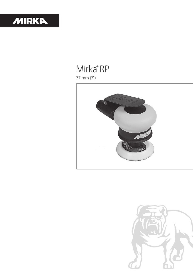
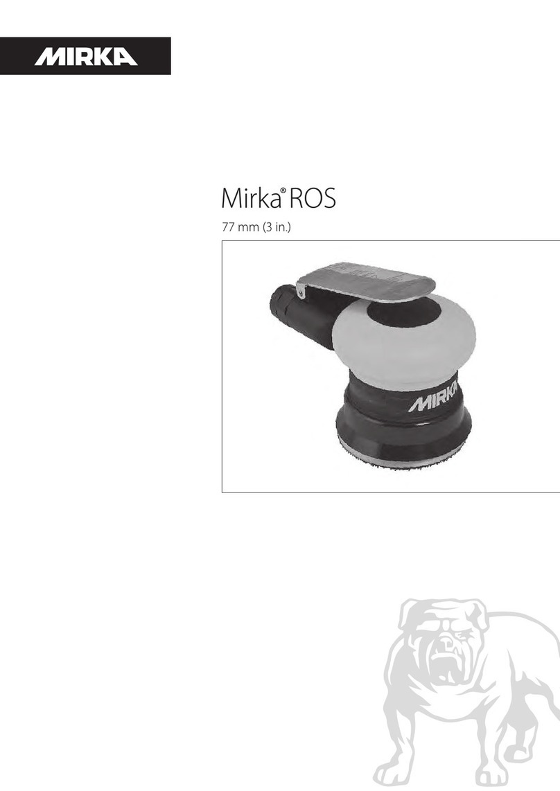
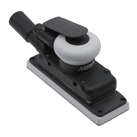
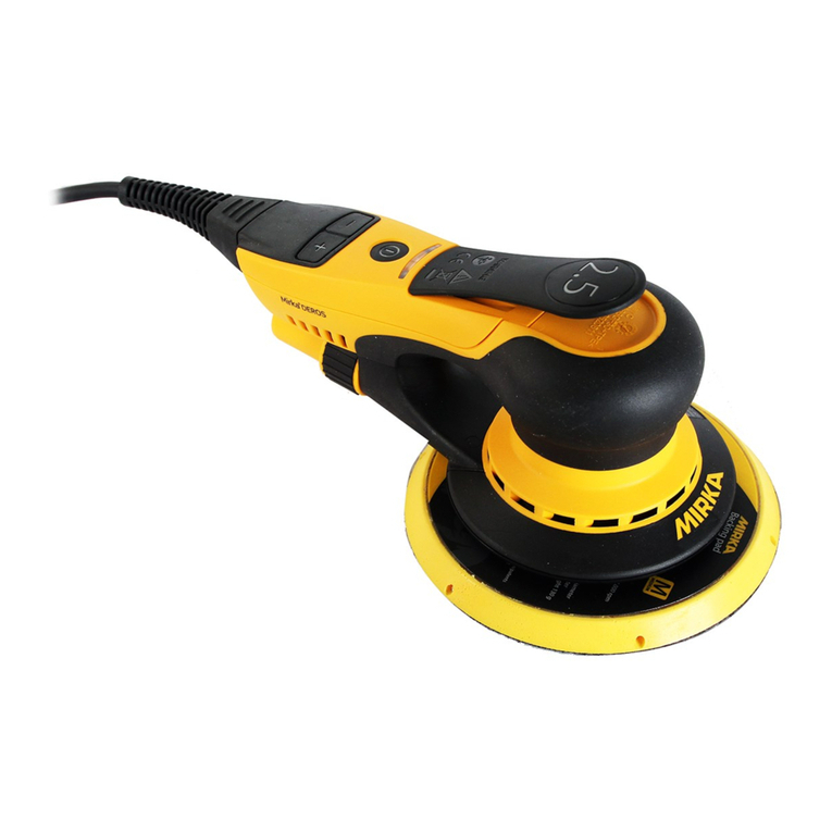
MIRKA ros650cv User manual

Random Orbital Sander
125 mm (5 in.) & 150 mm (6 in.)
English Operating Instructions 1-10
Deutsch Betriebsanleitung 11-21
Français Notice d´utilisation 22-32
Italiano Istruzioni sull´uso 33-43
Svensk Bruksanvisning 44-54
Suomi Käyttöohje 55-65
Español Instrucciones de manejo 66-76
Nederlands Gebruiksaanwijzing 77-87
Русский Руководство по эксплуатации 88-98
KWH Mirka Ltd
FIN-66850 JEPPO
Finland
Tel: +358-20-760 2111
sales@mirka.com
Mirka Abrasives, Inc.
7950 Bavaria Road
Twinsburg, Ohio 44087
USA
Tel. +1-330-963-6421
Mirka Slipmaterial AB
Blekegatan 4
S-65221 Karlstad
Sweden
Tel. + 46-54-690950
sales.se@mirka.com
Mirka Abrasives Ltd
Unit 7
Holdom Avenue , Bletchley
Milton Keynes MK1 1QU
Great Britain
Tel. +44-1908-375533
sales.uk@mirka.com
Mirka Abrasifs s.a.r.l.
Immeuble Atria
2, Allée Bienvenue
F-93885 Noisy le Grand Cedex
France
Tel. +33-1-4305 4800
ventes.fr@mirka.com
Mirka Schleifmittel GmbH
Niederhöchstädter Str. 71–73
D-61476 Kronberg Ts.
Germany
Tel. +49-6173-93450
info@mirka.de
Mirka Italia s.r.l
Via Toscana, 20
62014 Corridonia–Macerata
Italy
Tel. +39-0733-2075
info@mirkaitalia.com
KWH Mirka Iberica, S.A.
C/Industria 16-18
08740 Sant Andreu de la
Barca (Barcelona)
Spain
Tel. + 34 93 682 09 62
KWH Mirka Ltd
Branch Office
10 Anson Road
#28-05A International Plaza
Singapore 079903
Tel. +65-6733 5422
KWH Mirka Mexicana S.A. de C.V.
Boulevard Atlixcayotl No. 5506, Piso 5
Entre Kepler y Avenida del Sol
Reserva Territorial Atlixcayotl
Puebla, Puebla, C.P. 72190
Mexico.
Tel. +52 551 953 2019
KWH Mirka Ltd.
(Shanghai Representative Office)
Suite 1906A, Shenergy International
Building 1 Fuxing Rd(M),
Shanghai 200021 China
Tel: +86-21-6391 9371
sales.cn@mirka.com
Mirka Brasil Ltda.
Av.Ver. José Diniz, 3725 cj.32 – Campo Belo
São Paulo – SP
04603-004 Brasil
Phone: +55 11 5543 3639
Fax: +55 11 5543 3698
www.mirka.com
Random Orbital Sander
125 mm (5 in.) & 150 mm (6 in.)
English Operating Instructions 1-10
Deutsch Betriebsanleitung 11-17
Français Notice d´utilisation 19-25
Italiano Istruzioni sull´uso 27-33
Svensk Bruksanvisning 35-41
Norsk Brugsanvisning 43-49
Dansk Brugsanvisning 51-57
Suomi Käyttöohje 59-65
Español Instrucciones de manejo 67-73
Nederlands Gebruiksaanwijzing 75-81
Русский Руководствопоэксплуатации 83-89
Português Instruções de uso 91-97
Eesti Kasutusjuhend 99-105
Lietuvių Naudojimo instrukcija 107-113

1
Parts Page
NA
02/20/02
PWH
XPC0056
P/N
TITLE
X'POLE
XX/XX +/-NA
DRWN BY / DATE
MATERIAL
PROPRIETARY AND CONFIDENTIAL
PERMISSION OF X'POLE PRECISION TOOLS INC. IS PROHIBITED.
.XX +/-
DUCTION IN PART OR AS A WHOLE WITHOUT THE WRITTEN
CKD BY / DATE
PRECISION
NA
PROPERTY OF X'POLE PRECISION TOOLS INC.ANY REPRO-
ANGLES +/-
NA
NA
NA
ENG APP / DATE
12/12/01
STD TOL
TOOLS INC.
.X +/-
DRM
THE INFORMATION CONTAINED IN THIS DRAWING IS THE SOLE
.XXX +/-
PARTS PAGE FOR MIRKA 5 in. AND 6 in.
ROS
40
INLET
TO
DWG SCALE 1 : 31.
INLET
TO
2. ITEMS 46 AND 49 ARE TO BE RETAINED ON THE
61
1
2
3
4
5
6
7
8
9
10
11
12
13
14
15
16
18
19
20
21
22
23
24
25 26
27
28
29 30
31
32
33
34
35
36
38
37
39
BODY OF ITEM47 AND 50 USING ITEM48.
42
41
45
43
FOR CENTRAL VAC
TO VACUUM SYSTEM
46
47
50
48 49
51
52
53
54
55
56
57
58
59
60
44
NOTES:
62
RAG 11/08/10 PWH 11/09/10
-ITEMS 61 AND 62 WERE NOT ON
R
MJW 03/31/09 RAG 03/31/09
"XPA429" AND "XPA430"
"XPA1699" WERE "XPA427" "XPA428"
-ITEM 23: LEVERS "XPA1698" AND
-ITEM 17: "N/A" WAS "XPA917" SHIM
"XPB0075"
"XPB0072" "XPB0073" "XPB0074" AND
"XPB0280" WERE STD BALANCERS
"XPB0277" "XPB00278" "XPB0079" AND
-ITEM 13: BiasBALANCED BALANCERS
1 in./28 mm HOSE SEALXPA077846
1SGV RETAINERXPA000645
214.0 x 1.5 O-RINGXPA004444
11/4-18 NPT INLET BUSHING ASSEMBLY
INSERT FOR MIRKA VACUUM BAGXPA046459
1HEX SOCKET BUTTON HEAD MACHINE SCREW M5 x 10XPA076958
1M5 WASHERXPA004757
OPTROS SuperVAC CV 3/4 in. SWIVEL EXHAUST ASSEMBLYXPA020556
1M5 x 0.8 FLANGED NUTXPA004855
1ROS SuperVAC™ CV 1 in./28 mm SWIVEL EXHAUST ASSEMBLYXPA009954
1Ø 1 in. VAC HOSE TO DOUBLE BAG FITTING AND AIRLINE ASSYXPA041253
OPTØ 3/4 in. VAC HOSE TO DOUBLE BAG FITTING AND AIRLINE ASSYXPA041153
1Ø 1 in. VAC HOSE TO Ø 1 in./28 mm x 1 1/2 in. ADAPTOR COUPLING AND AIRLINE ASSEMXPA039252
OPTØ 3/4 in. VAC HOSE TO Ø 3/4 in. x 1 in./28 mm ADAPTER COUPLING AND AIRLINE ASSMXPA030052
1SuperVAC SGV SKIRT/SHROUD ADAPTERXPC010851
OPTASSEMBLY FOR 3/4 in./19 mm HOSE SuperVAC SWIVEL EXHAUST FITTINGXPA040950
OPT3/4 in./19 mm HOSE SEALXPA085449
1MIRKA 1 in./28 mm HOSE SEAL TAG W/INSTRUCTIONXPA093148
OPTMIRKA 3/4 in./19 mm HOSE SEAL TAG W/INSTRUCTIONXPA085648
1ASSEMBLY FOR 1 in./28 mm HOSE SuperVAC SGV SWIVEL EXHAUST FITTINGXPA041047
1
1SPINDLE BEARING DUST SHIELDXPA254262
1FRONT BEARING DUST SHIELDXPA254161
1VACUUM BAGXPC011060
1
YTQNOITPIRCSEDN/PTI
1GNIRGNINIATERLANRETXE0400APX1
1SDLEIHS2-
GNIRAEB8X62X011200APX2
3 XPB0017REAR ENDPLATE 1
1YLBMESSAREDNILYC5000APX4
1GNIR-Omm0.2xmm52400APX5
6 XPB0005 MACHINED ROTOR 1
7 XPA0010VANE 5
1YEKFFURDOOWmm31xmm31400APX8
9 XPB0016FRONT ENDPLATE 1
1SDLEIHS2-GNIRAEB8X82X219100APX01
1GNIR-Omm1.3xmm4.935400APX11
12 XPA0001LOCK RING 1
13 XPB0279 5 x 3/32 in ORBIT AirS 1RECNALABTFAHS™sulPDLEIH
13 XPB02806 x3/32 in. ORBIT Ai 1RECNALABTFAHS™sulPDLEIHSr
13 XPB02775 x3/16 in ORBIT Ai 1RECNALABTFAHS™sulPDLEIHSr
13 XPB02786 x3/16 in. ORBIT Ai 1RECNALABTFAHS™su
lPDLEIHSr
14 XPA0122FILTER 1
1EVLAVKCEHCLLIBKCUD1210APX51
16 XPA0120VALVE RETAINER 1
17 N/A N/A -
18 XPA093812 x 28 x 16 DOUBLE ROW AN 1LAES1-GNIRAEBTCATNOCRALUG
1KHT2.0xDO0.81xDI1.21RECAPS6100APX91
1REHSAWELLIVELLEB7100APX02
21 XPA0018RETAINING RING 1
22 XPB0018SPINDLE 1
23 XPA1698THROTTLE LEVERFOR MIRKA 12,000 RPM 2.5 mm (3/32 in.) ORBIT SANDERS 1
23 XPA1699THROTTLE LEVERFOR MIRKA 12,000 RPM 5 mm (3/16 in.) ORBIT SANDERS 1
24 XPA0031LEVER SPRING PIN 1
TPOC321SMPWOLLEY.ni2/12,PIRG8820APX52
TPOC321SMPWOLLEYni4/32,PIRG9820APX52
1C321SMPWOLLEY.ni3,PIRG0920APX52
26 XPA0015VALVE SLEEVE 1
1GNISUOHDENIHCAM4420APX
72
1YLBMESSAMETSEVLAV8000APX82
1GNIR-Omm5.1xmm93400APX92
30 XPB0014SPEED CONTROL 1
1GNIRGNINIATERLANRETNI9300APX13
1DUORHSMUUCAV-NON.ni6/52100BPX23
1DUORHS™CAVrepuS.ni6/52100CPX33
34 XPC0073Ø 6 in. SCREEN ABRA 1DUORHS™CAVrepuSSOREVIS
1HCNERWDAPmm422200APX53
36 NA (ONE BACKUP PAD SUPPLIED WITH EACH TOOL - TYPE/SIZE MODEL DEPENDENT) 1
1RELFFUMLANRETNI2600APX73
38 XPA0068 MUFFLER INSERT 1
1GNISUOHRELFFUM6610APX93
40 XPA0009VALVE SEAT 1
41 XPA0007VALVE 1
42 XPA0014VALVE SPRING 1
43 XPA0013
REVISION RECORD
R DESCRIPTION / DATE
J
-ITEM 58 WAS THE INDIVIDUAL P/N FOR
THE VACUUM BAG (XPC0110) AND NOT THE
REORDER P/N's FOR 19 mm AND 28 mm
VACUUM BAG ASSEMBLIES
-ITEM 59 WAS TH EINDIVIDUAL P/N FOR
THE VACUUM BAG INSERT (XPA0464) AND
NOT THE 10 PACK P/N (XPA0465)
DRM 06/14/04 PWH 06/14/04
K
-XPA0769 SCREW (ITEM 57) WAS XPA0046
SCREW
-XPA0465 10 PACK OF VACUUM BAG
INSERTS (ITEM 59) WAS 8993206511 10
PACK OF VACUUM BAG INSERTS
RAG 12/14/04 PWH 12/31/04
L
-ITEM 7: DESC. WAS "....item 8 set)", QTY
WAS 1
-ITEM 8: P/N WAS XPA063, DESC. WAS
"...AND KEY SET."
-ITEM 9: DESC. WAS "...item 8 set)"
-ITEM 38 WAS STANDARD VACUUM PAD
-ITEM 39 P/N WAS XPA0096, DESC. WAS
"MUFFLER HOUSING ( includes...)
RAG 03/07/05 PWH 03/14/05
M
-ITEM 29: DESC. WAS "...includes item 29 o-
ring)"
-ITEM 30: DESC. WAS "...included with item
28)"
-ITEM 58 P/N XPC0110 WAS XPA0658
-ITEM 58 DESC. WAS "VACUUM BAG (one
included) WITH 19 mm ( 3/4 in.) AND 28 mm ( 1
in. ) VACUUM BAG FITTINGS
RAG 08/01/05 PWH 11/11/05
N
-DRAWING WAS NOT IN SOLIDWORKS
-DRAWING WAS NOT IN NEW "PARTS
PAGE" FORMAT, WITH REPLACMENT SETS
REMOVED AND LISTED SEPARATELY IN
MANUALS
-ITEMS AFTER 3 WERE NOT RENUMBERED
-ITEMS WERE NOT STANDARD
SOLIDWORKS TITLES.
-PART NUMBERS XPA0004, XPA0020,
XPA0035, XPA0098 XPA0193, XPA0465,
XPA0797, XPA0797, XPA0801 WERE NOT
REMOVED.
-PART NUMBERS XPA0016, XPA0778,
XPA0854, XPA0856, XPA0931, XPA0937,
XPA0938, XPB0005, XPC0109 WERE NOT
ADDED
-OLD ITEM 51 SPLIT INTO NEW ITEMS 52
AND 53 (CV AND SGV HOSE ASSYS WERE
NOT SEPARATED.)
-METRIC CONVERSIONS WERE NOT ON
TORQUE SPECS.
-NOTES WERE NOT ON
MJW 05/08/06 PWH 05/08/06
P
-PARTS "XPA0062" AND " XPA0068" (ITEMS
37 AND 38) POSITIONS AND ITEM NUMBERS
WERE NOT SWITCHED.
-TORQUE SETTING TABLE WAS NOT ON,
INDIVIDUAL TORQUE NOTES WERE NOT
REMOVED.
-QTY "OPT" OF ITEM 25 (XPA0288 AND
XPA0299), ITEM 48 (XPA0856), AND ITEM 49
WAS "1".
-REVISION "N" YEAR "06" WAS
INCORRECTLY "02" IN SIGN-OFFS..
MJW 05/22/06 PWH 05/27/06
Q
ITEMTORQUE SETTING
in.-lbs. (Nm)
12 55 - 65 (6.2 - 7.3)
39 16 - 20 (1.8 - 2.3)
43 60 - 72 (6.8 - 8.1)
45 36 - 48 (4.1 - 5.2)
58 30 - 35 (3.4 - 3.9)
F
E
I
J
C
A
H
K
I
G
D
B
L
Original Instructions
I
M

2
Parts List
Item P/N Description Qty.
1 MPA0040 RETAINING RING 1
2 MPA0021 BEARING 1
3 MPB0017 REAR ENDPLATE 1
4 MPA0005 CYLINDER ASSEMBLY 1
5 MPA0042 O-RING 1
6 MPB0005 ROTOR 1
7 MPA0010 VANE 5
8 MPA0041 KEY 1
9 MPB0016 FRONT ENDPLATE 1
10 MPA0019 BEARING 1
11 MPA0045 O-RING 1
12 MPA0001 LOCK RING 1
13
MPB0277 5 mm (3/16 in.) ORBIT AirSHIELD™ SHAFT BALANCER FOR 125 mm (5 in.) PADS 1
MPB0278 5 mm (3/16 in.) ORBIT AirSHIELD™ SHAFT BALANCER FOR 150 mm (6 in.) PADS 1
MPB0279 2.5 mm (3/32 in.) ORBIT AirSHIELD™ SHAFT BALANCER FOR 125 mm (5 in.) PADS 1
MPB0280 2.5 mm (3/32 in.) ORBIT AirSHIELD™ SHAFT BALANCER FOR 150 mm (6 in.) PADS 1
14 MPA0122 FILTER 1
15 MPA0121 CHECK VALVE 1
16 MPA0120 RETAINER 1
17 N/A
18 MPA0938 DOUBLE ROW BEARING 1
19 MPA0016 SPACER 1
20 MPA0017 WASHER 1
21 MPA0018 RETAINING RING 1
22 MPB0018 SPINDLE 1
23 MPA1699 LEVER FOR 12,000 RPM, 125 mm (5 in.) / 150 mm (6 in.) PADS 5 mm (3/16 in.) ORBIT MACHINES 1
MPA1698 LEVER FOR 12,000 RPM, 125 mm (5 in.) / 150 mm (6 in.) PADS 2.5 mm (3/32 in.) ORBIT MACHINES 1
24 MPA0031 PIN 1
25
MPA0288 65 mm (2 1/2 in.) GRIP (Optional) OPTIONAL
MPA0289 70 mm (2 3/4 in.) GRIP (Optional) OPTIONAL
MPA0290 75 mm (3 in.) GRIP (Standard)) 1
26 MPA0015 SLEEVE 1
27 MPA0244 HOUSING 1
28 MPA0008 VALVE STEM ASSEMBLY 1
29 MPA0043 O-RING 1
30 MPB0014 SPEED CONTROL 1
31 MPA0039 RETAINING RING 1
32 MPB0012 125/150 mm (5/6 in.) NON-VACUUM SHROUD 1
33 MPC0012 SuperVAC™ SHROUD for 125 mm (5 in.) Delta, TE, LP and Screen Abrasive pads 1
34 MPC0073 SuperVAC™ SHROUD for 150 mm (6 in.) Screen Abrasive and LP Pads 1
35 MPA0022 24 mm PAD WRENCH (supplied with each tool) 1
36 NA SEE LITERATURE FOR PADS (type/size determined by model) 1
37 MPA0062 INTERNAL MUFFLER (for 12,000 RPM Machines) 1
38 MPA0068 MUFFLER INSERT(for 12,000 RPM Machines) 1
39 MPA0166 MUFFLER HOUSING 1
40 MPA0009 SEAT 1
41 MPA0007 VALVE 1
42 MPA0014 VALVE SPRING 1
43 MPA0013 INLET BUSHING 1
44 MPA0044 O-RING 2
45 MPA0006 SGV RETAINER 1
46 MPA0778 28mm (1 in.) HOSE SEAL 1
47 MPA0410 28 mm (1 in.) HOSE SuperVAC™ SGV SWIVEL EXHAUST ASSEMBLY (Standard for SGV)) 1
48 MPA0856 19mm (3/4 in.) HOSE SEAL TAG OPTIONAL
MPA0931 28mm (1 in.) HOSE SEAL TAG 1
49 MPA0854 19mm (3/4 in.) HOSE SEAL OPTIONAL
50 MPA0409 19 mm (¾ in.) HOSE SuperVAC™ SGV SWIVEL EXHAUST ASSEMBLY (Optional for SGV) OPTIONAL
51 MPC0108 SuperVAC™ SGV EXHAUST ADAPTER (for use with SuperVAC™ Shroud) 1
52
MPA0300
Ø 19 mm (¾ in.) VAC HOSE TO Ø 19 mm (¾ in.) x Ø 28 mm (1 in.) HOSE ADAPTER COUPLING AND AIRLINE
ASSEMBLY INCLUDES: MPA0200 Ø 19 mm (¾ in.) x 1.5 m (5 ft.) Vacuum Hose, MPB0088 19 mm (¾ in.) Hose x
28 mm (1 in.) Hose Adapter, MPA0302 Ø 6.3 mm (¼ in.) x 1.5 m (5 ft.) Airline with Fittings, MPA0301 Bungee for Ø
6.3 mm (¼ in.) Airline & Ø 19 mm (¾ in.) Vacuum Hose (5)
OPTIONAL
MPA0392
Ø 28 mm (1 in.) VAC HOSE TO Ø 28 mm (1 in.) x Ø 38 mm (1 ½ in.) FRICTION FIT ADAPTER AND AIRLINE
ASSY. (Optional) INCLUDES: MPA0034 Ø 28 mm (1 in.) x 1.8 m (6 ft.) Vacuum Hose, MPB0092 Ø 28 mm (1 in.)
Hose Thread x Ø 38 mm (1 ½ in.) Friction Fit Adapter, MPA0033 Ø 6.3 mm (¼ in.) x 1.8 m (6 ft.) Airline with Fittings,
MPA0027 Bungee for Ø 6.3 mm (¼ in.) Airline & Ø 28 mm (1 in.) Vacuum Hose (5)
OPTIONAL
53
MPA0412
Ø 28 mm (1 in.) VAC HOSE TO Ø 28 mm (1 in.) DOUBLE BAG FITTING AND AIRLINE ASSY. (Standard for SGV)
INCLUDES: MPA0034 Ø 28 mm (1 in.) x 1.8 m (6 ft.) Vacuum Hose, MPB0123 Ø 28 mm (1 in.) Hose to Double Bag
Vacuum Fitting, MPA0033 Ø 6.3 mm (¼ in.) x 1.8 m (6 ft.) Airline with Fittings, MPA0027 Bungee for Ø 6.3 mm (¼
in.) Airline & Ø 28 mm (1 in.) Vacuum Hose (5)
1
MPA0411
Ø 19 mm (¾ in.) VAC HOSE TO Ø 19 mm (¾ in.) DOUBLE BAG FITTING AND AIRLINE ASSEMBLY (Optional for
SGV) INCLUDES: MPA0200 Ø 19 mm (¾ in.) x 1.5 m (5 ft.) Vacuum Hose, MPB0133 Ø 19 mm (¾ in.) Hose To
Double Bag Vacuum Fitting, MPA0302 Ø 6.3 mm (¼ in.) x 1.5 m (5 ft.) Airline with Fittings, MPA0301 Bungee for Ø
6.3 mm (¼ in.) Airline & Ø 19 mm (¾ in.) Vacuum Hose (5)
OPTIONAL
54 MPA0099 SuperVAC™ CV 28 mm (1 in.) SWIVEL EXHAUST ASSEMBLY (Standard for CV) 1
55 MPA0048 NUT 1
56 MPA0205 SuperVAC™ CV 19 mm (¾ in.) SWIVEL EXHAUST ASSEMBLY (Optional for CV) OPTIONAL
57 MPA0047 WASHER 1
58 MPA0769 SCREW 1
59 MPA0465 10 PACK OF VACUUM BAG INSERTS 1
60 MPC0110 VACUUM BAG 1
61 MPA2541 FRONT BEARING DUST SHIELD 1
62 MPA2542 SPINDLE BEARING DUST SHIELD 1

3
Sander Spare Parts Kits
Scaled 50%
AMPA0797 12,000 RPM
MuferKit
Code: 8993017311 BMPA0802 ROS
Spindle Bearing Kit
Code: 8993019711
CMPA0798 Air Inlet Kit
Code: 8993018811
IMPA0799 Endplate
Bearing Kit
Code: 8993019811
JMPA0800 Speed
Valve Kit
Code: 8993019011
KMPA0801 Rotor, Vanes
& Key Kit
Code: 8993017711
MMPA2551 SGV
Retainer Kit
Code: 8993018911
Scaled 50%
Scaled 50%
DMPA0980 Shaft Balancer Kit
150mm/5,0 Kit
Code: 8993010611
MPA1670 Shaft Balancer Kit
150mm/2,5 Kit
Code: 8993013711
EMPA0988 CV Swivel
Fitting Kit
Code: 8993006611
FMPA0994 Cylinder & O-ring Kit
Code: 8993009211 GMPA0993 Lock Ring &
O-ring Kit
Code: 8993007911
HMPA0932 SGV Swivel
Fitting Kit
Code: 8993011311
LMPA0983 Lever Kit
5.0 mm orbit
Code: 8993010811
MPA0984 Lever Kit
2.5 mm orbit
Code: 8993010911
REVISED 05/26/09

4
MIRKA 12,000 RPM
125 mm (5 in.) & 150 mm (6 in.)
RANDOM ORBITAL SANDERS
The warranty terms are as follows:
- 12 months on KWH MIRKA air tools.
- 3 months on tool parts repaired by KWH MIRKA.
The warranty period commences at the date of purchase. The warranty only covers imputable material and manu-
facturing defects.
PartsreplacementorrepairduringthewarrantyperiodisfreeofchargeifcarriedoutbyanofcialKWHMIRKA
service center.
Freight costs are always to be paid by the purchaser.
The warranty does not include:
Normal wear and tear i.e.
- Bearings,backingpad,shroud,rotor,vanes,swiveltting,mufer
Overloading or improper use i.e.
- Dropping the tool in water
- Damage caused by misuse
- Damage caused by anything other than defects in material and workmanship
- Dropping or other excessive impact
Normal maintenance and service that can be carried out by the operator:
- Changing of the backing pad
- Changing of the spindle bearing
- Changingoftheexhausttting
- Changing of the shroud
Please Note! All other service operations must be carried out by an authorized Mirka service center.
The warranty only covers the local repair, not the tool replacement.
Compensation for downtime and loss of production are explicitly not included in the warranty.
Repair claims under warranty will only be honored if the tool is returned in its original assembled state. Any disas-
sembly will void the warranty.
The warranty can only be submitted to the dealers where the tool was purchased.
Warranty
Manufacturer/Supplier
KWH Mirka Ltd.
66850 Jeppo, Finland
Tel: + 358 20 760 2111
Fax: +358 20 760 2290
Required Personal Safety Equipment
Safety Glasses Breathing Masks
Safety Gloves Ear Protection
Recommended Airline
Size - Minimum
10 mm 3/8 in
Recommended Maximum
Hose Length
8 meters 25 feet
Air Pressure
Maximum Working Pressure 6.2 bar 90 psig
Recommended Minimum NA NA
Operator Instructions
Includes – Warranty, Please Read and Comply, Proper Use of
Tool, Work Stations, Putting the Tool Into Service, Operating
Instructions,ProductConguration/SpecicationsTables,
Parts Page, Parts List, Sander Spare Parts Kits, Trouble
Shooting Guide, Service Instructions
Declaration of conformity
KWH Mirka Ltd.
66850 Jeppo, Finland
declare on our sole responsibility that the products
125mm(5in.)and150mm(6in.)12,000RPMRandomOrbitalSanders(See“ProductConguration/Specications”Tablefor
particular Model) to which this declaration relates is in conformity with the following standard(s) or other normative document(s) EN ISO
15744:2008. Following the provisions of 89/392/EEC as amended by 91/368/EEC & 93/44/EEC 93/68/EEC Directives and consolidating
Directive 2006/42/EC
Place and date of issue Name Signature or equivalent marking of authorized person
Important
Read these instructions care-
fully before installing, operating,
servicing or repairing this tool.
Keep these instructions in a safe
accessible location.
Tom Nordström08.01.2010 Jeppo

5
Closed Loop Pipe System
Sloped in the direction of air flow
Drain Leg
Ball Valve
To Tool Station
Filter
Drain Valve
Regulator
Lubricator
Ball
Valve
Ball Valve Air Flow
Air Dryer
Air Compressor
and Tank
Air Hose
To Coupler
at or near Tool
Please Read and Comply with Putting the Tool into Service
Operating Instructions
1) Read all instructions before using this tool. All operators must be fully trained in its use
and aware of these safety rules. All service and repair must be carried out by trained
personnel.
2) Make sure the tool is disconnected from the air supply. Select a suitable abrasive and
secure it to the back-up pad. Be careful and center the abrasive on the back-up pad.
3) Always wear required safety equipment when using this tool.
4) When sanding always place the tool on the work then
start the tool. Always remove the tool from the work
before stopping. This will prevent gouging of the work
due to excess speed of the abrasive.
5) Alwaysremovetheairsupplytothesanderbeforet-
ting, adjusting or removing the abrasive or back-up pad.
6) Alwaysadoptarmfootingand/orpositionandbe
aware of torque reaction developed by the sander.
7) Use only correct spare parts.
8) Alwaysensurethatthematerialtobesandedisrmly
xedtopreventitsmovement.
9)Checkhoseandttingsregularlyforwear.Donotcarry
the tool by its hose; always be careful to prevent the
tool from being started when carrying the tool with the
air supply connected.
10) Dust can be highly combustible. Vacuum dust collection
bag should be cleaned or replaced daily. Cleaning or
replacing of bag also assures optimum performance.
11) Do not exceed maximum recommended air pressure.
Use safety equipment as recommended.
12) The tool is not electrically insulated. Do not use where
there is a possibility of coming into contact with live
electricity, gas pipes, water pipes, etc. Check the area
of operation before operation.
13) Take care to avoid entanglement with the moving parts
of the tool with clothing, ties, hair, cleaning rags, etc. If entangled, it will cause the body
to be pulled towards the work and moving parts of the machine and can be very danger-
ous.
14) Keep hands clear of the spinning pad during use.
15) If the tool appears to malfunction, remove from use immediately and arrange for service
and repair.
16) Do not allow the tool to free speed without taking precautions to protect any persons or
objects from the loss of the abrasive or pad.
Work Stations
Proper Use of Tool
1) General Industry Safety & Health Regulations, Part 1910,
OSHA 2206, available from: Superintendent of Documents;
GovernmentPrintingOfce;WashingtonDC20402
2) Safety Code for Portable Air Tools, ANSI B186.1 available from:
American National Standards Institute, Inc.; 1430 Broadway;
New York, New York 10018
3) State and Local Regulations.
This sander is designed for sanding all types of materials i.e.
metals, wood, stone, plastics, etc. using abrasive designed for this
purpose. Do not use this sander for any other purpose than that
speciedwithoutconsultingthemanufacturerorthemanufac-
turer’s authorized supplier. Do not use back-up pads that have a
working speed less than 12,000 RPM free speed.
The tool is intended to be operated as a hand held tool. It is
always recommended that the tool be used when standing on a
solidoor.Itcanbeinanypositionbutbeforeanysuchuse,the
operatormustbeinasecurepositionhavingarmgripandfoot-
ing and be aware that the sander can develop a torque reaction.
Seethesection“OperatingInstructions”.
Use a clean lubricated air supply that will give a measured air
pressure at the tool of 6.2 bar (90 psig) bar when the tool is run-
ning with the lever fully depressed. It is recommended to use an
approved 10 mm (3/8 in.) x 8 m (25 ft) maximum length airline. It
is recommended that the tool be connected to the air supply as
shown in Figure 1.
Do not connect the tool to the airline system without incorporating
an easy to reach and operate air shut off valve. The air supply
shouldbelubricated.Itisstronglyrecommendedthatanairlter,
regulator and lubricator (FRL) be used as shown in Figure 1 as
this will supply clean, lubricated air at the correct pressure to
the tool. Details of such equipment can be obtained from your
supplier. If such equipment is not used then the tool should be
manually lubricated
To manually lubricate the tool, disconnect the airline and put 2 to
3 drops of suitable pneumatic motor lubricating oil such as Fuji
Kosan FK-20, Mobil ALMO 525 or Shell TORCULA® 32 into the
hose end (inlet) of the machine. Reconnect tool to the air supply
and run tool slowly for a few seconds to allow air to circulate the
oil. If the tool is used frequently, lubricate it on a daily basis or
lubricate it if the tool starts to slow or lose power.
It is recommended that the air pressure at the tool is 6.2 bar (90
psig) while the tool is running. The tool can run at lower pressures
but never higher than 6.2 bar (90 psig).

6
Orbit Vacuum
Type
Pad
Size mm
(inch)
Model
Number
Product Net
Weight kg
(pounds)
Height mm
(inch)
Length mm
(inch)
*Noise
Level
dBA
Power
watts
(HP)
Air Consumption
LPM (scfm)
*Vibration
Level
m/s2
*Uncertainty
K
m/s2
2.5 mm
(3/32 in.)
Non-Vacuum 125 (5) ROS525NV 0.72 (1.59) 82.9 (3.26) 148.4 (5.84) 79 209 (0.28) 481 (17) 2.1 1.1
150 (6) ROS625NV 0.76 (1.68) 82.9 (3.26) 161.1 (6.34) 83 209 (0.28) 481 (17) 3.3 1.7
Central
Vacuum
125 (5) ROS525CV 0.78 (1.72) 87.7 (3.45) 148.4 (5.84) 79 209 (0.28) 481 (17) 2.1 1.1
150 (6) ROS625CV 0.85 (1.87) 82.9 (3.26) 161.1 (6.34) 83 209 (0.28) 481 (17) 3.3 1.7
Shrouded
Self-Gen.
Vacuum
150 (6) ROS625DB 0.85 (1.87) 82.9 (3.26) 164.1 (6.46) 83 209 (0.28) 481 (17) 3.1 1.6
5.0 mm
(3/16 in.)
Non-Vacuum 125 (5) ROS550NV 0.75 (1.65) 82.9 (3.26) 149.6 (5.89) 80 209 (0.28) 481 (17) 2.6 1.3
150 (6) ROS650NV 0.79 (1.74) 82.9 (3.26) 162.3 (6.39) 79 209 (0.28) 481 (17) 3.7 1.9
Central
Vacuum
125 (5) ROS550CV 0.81 (1.79) 87.7 (3.45) 149.6 (5.89) 79 209 (0.28) 481 (17) 2.6 1.3
150 (6) ROS650CV 0.85 (1.87) 82.9 (3.26) 162.3 (6.39) 77 209 (0.28) 481 (17) 3.1 1.6
Shrouded
Self-Gen.
Vacuum
125 (5) ROS550DB 0.83 (1.83) 87.7 (3.45) 152.6 (6.01) 85 209 (0.28) 481 (17) 3.5 1.8
150 (6) ROS650DB 0.88 (1.94) 82.9 (3.26) 165.3 (6.51) 85 209 (0.28) 481 (17) 3.5 1.8
The noise test is carried out in accordance with EN ISO 15744:2008 - Hand-held non-electric power tools -- Noise measurement code -- Engi-
neering method (grade 2).
The vibration test is carried out in accordance with EN 28662-1 Hand-held portable power tools – Measurement of vibration at the handle. Part 1:
General and EN 8662-8, 1997 Hand-held portable power tools – Measurement of vibration at the handle. Part 8: Polishers and rotary, orbital and
random orbital sanders.
Specicationssubjecttochangewithoutpriornotice.
*Thevaluesstatedinthetablearefromlaboratorytestinginconformitywithstatedcodesandstandardsandarenotsufcientforrisk
evaluation. Values measured in a particular work place may be higher than the declared values. The actual exposure values and amount
of risk or harm experienced to an individual is unique to each situation and depends upon the surrounding environment, the way in which
the individual works, the particular material being worked, work station design as well as upon the exposure time and the physical condi-
tion of the user. KWH Mirka, Ltd. cannot be held responsible for the consequences of using declared values instead of actual exposure
values for any individual risk assessment.
Further occupational health and safety information can be obtained from the following websites:
http://europe.osha.eu.int (Europe)
http://www.osha.gov (USA)
ProductConguration/Specications:12,000RPMRandomOrbitalSander

7
Symptom Possible Cause Solution
Low Power and/or Low Free
Speed
InsufcientAirPressure Check air line pressure at the Inlet of the Sander
while the tool is running at free speed. It must be
6.2 Bar (90 psig/620 kPa).
CloggedMufer(s) Seethe“HousingDisassembly”sectionforMufer
removal.TheItem37Mufercanbebackushed
with a clean, suitable cleaning solution until all con-
taminates and obstructions have been removed.
IftheMufercannotbeproperlycleanedthen
replaceit.ReplaceItem38,MuferInsert(Seethe
“HousingAssembly”Section).
Plugged Inlet Screen Clean the Inlet Screen with a clean, suitable
cleaning solution. If Screen does not come clean
replace it.
One or more Worn or Broken Vanes Install a complete set of new Vanes (all vanes must
be replaced for proper operation). Coat all vanes
with quality pneumatic tool oil. See “Motor Disas-
sembly”and“MotorAssembly”.
Internal air leakage in the Motor Housing
indicated by higher than normal air con-
sumption and lower than normal speed.
Check for proper Motor alignment and Lock Ring
engagement. Check for damaged O-Ring in Lock
Ring groove. Remove Motor Assembly and Re-In-
stalltheMotorAssembly.See“MotorDisassembly”
and“MotorAssembly”.
Motor Parts Worn Overhaul Motor. Contact authorized Mirka Service
Center.
Worn or broken Spindle Bearings Replace the worn or broken Bearings. See “Shaft
BalancerandSpindleDisassembly”and“Spindle
Bearings, AirSHIELD™ and Shaft Balancer As-
sembly”.
Air leakage through the Speed
Control and/or Valve Stem.
Dirty, broken or bent Valve Spring, Valve
or Valve Seat.
Disassemble, inspect and replace wore or dam-
aged parts. See Steps 2 and 3 in “Housing Disas-
sembly”andSteps2and3in“HousingAssembly”.
Vibration/Rough Operation
Incorrect Pad Only use Pad Sizes and Weights designed for the
machine.
Addition of interface pad or other material Only use abrasive and/or interface designed for the
machine. Do not attach anything to the Sanders
Padfacethatwasnotspecicallydesignedtobe
used with the Pad and Sander.
Improper lubrication or buildup of foreign
debris.
Disassemble the Sander and clean in a suitable
cleaning solution. Assemble the Sander. (See
“ServiceManual”)
Worn or broken Rear or Front Motor
Bearing(s)
Replace the worn or broken Bearings. See “Motor
Disassembly”and“MotorAssembly”.
For vacuum machines it is possible to
have too much vacuum while sanding on a
atsurfacecausingthepadtosticktothe
sanding surface.
For SGV machines add extra washer(s) to the pad
spindle to increase the gap between the pad and
shroud. For CV machines reduce vacuum through
the vacuum system and/or add extra washer(s)
to the pad.
Troubleshooting Guiide
Note:AllSectionsreferredtounder“Solution”arelocatedattheendofthemanualin“ServiceInstructions”

8
MIRKA 12,000 RPM
125 mm (5 in.) & 150 mm (6 in.)
RANDOM ORBITAL SANDERS
SERVICE INSTRUCTIONS
NOTICE: To receive any expressed or implied warranty, tool must be repaired by an authorized Mirka Service Center. The following
general service instructions provided are for use after completion of the warranty period.
DISASSEMBLY INSTRUCTIONS
Changing Grips:
1. The(25)Griphastwo“tabs”thatwraparoundthebodyofthe
sander under the inlet and exhaust. Use a small screwdriver
topickoutoneofthe“tabs”oftheGrip,andthencontinueto
go underneath the Grip with the screwdriver and pry the Grip
off of sander. To install a new Grip, hold the Grip by the tabs
making them face outward, align the Grip and slide it under
the (23) Throttle Lever then press the Grip down until it seats
ontothetopofthesander.Makesurethetwo“tabs”seat
under the inlet and exhaust.
Motor Disassembly:
1. Lightly secure the tool in a vise using the (MPA0026) T-7 Soft
Collar or padded jaw vice and remove the (36) pad with the
(35) 24 mm Pad Wrench then remove the Shroud or Skirt
(whichever applies).
2. Remove the (12) Lock Ring with the (MPA0025) T-6 Motor
Lock Ring Wrench/Spindle Puller Tool. The motor assembly
can now be lifted out of the (27) Housing.
3. Secure the motor assembly by clamping the (13) Shaft
Balancer in a padded jaw vise and remove the (1) Retaining
Ring and the (5) O-Ring from the (4) Cylinder.
4. Remove the (3) Rear Endplate. This may require supporting
the(3) Rear Endplate with a (MPA0416) Bearing Separator
and lightly pressing the shaft through the (2) Bearing and
RearEndplate.Removethe(4)Cylinderandtheve(7)
Vanes and (6) Rotor Set from the shaft of the Shaft Balancer.
Remove the (8) Key then press off the (9) Front Endplate
(with [10] Bearing), (11) O-Ring and the (12) Lock Ring. It
may be necessary to remove the Bearing with a Bearing
Separator if it came out of the Front Endplate and stuck to the
shaft of the Shaft Balancer.
5. Remove and discard (61) Dust Shield from the (13) Shaft
Balancer.
6. Remove the bearing(s) from the endplates by using the
(MPA0036) T-8 Bearing Removal Tool to press out the bear-
ings.
Shaft Balancer and Spindle Disassembly:
1. Grip the shaft end of the (13) Shaft Balancer in a padded
vise. With a thin screwdriver pick out the slotted end of the
(21) Retaining Ring and peel out.
2. Screw the threaded end of the (MPA0025) T-6 Motor Lock
Ring Wrench/Spindle Puller Tool into the (22) Spindle until
hand tight. Apply a gentle heat from a propane torch or hot
air gun to the large end of the Balancer Shaft until it is about
100° C (212° F) to soften the adhesive. Do not over heat. Re-
move the Spindle assembly by using the slider to give sharp
outward blows to the Spindle. Allow the parts to cool so they
are safe to handle. Follow one of the appropriate directions
below:
• IftheBearingcomesoutwiththespindle,useasmall
Bearing Separator to remove it. Move onto step 3.
• IftheBearingstaysinthe(13)ShaftBalancer.Follow
steps A - D below.
Procedure for removal of the Bearings from the Shaft
Balancer:
A. Position the Set Screw in the top of the (MPA0059) T-9 12
mm ID Bearing Puller.
B. Make sure the (21) Retaining Ring is removed, then press the
Bearing Puller into the I.D. of Bearing until the Bearing Puller
hits the bottom of the Shaft Balancer.
C. Thread the Set Screw down until it hits the bottom of the (13)
Shaft Balancer or becomes very tight. Grip the shaft end of
the Shaft Balancer in a padded vise.
D. Screw the threaded end of the (MPA0025) T-6 Motor Lock
Ring Wrench/Spindle Puller Tool into the Bearing Puller until
hand tight. Apply a gentle heat from a propane torch or hot
air gun to the large end of the (13) Shaft Balancer to re-heat
it until it is about 100° C (212° F) to soften the adhesive. Do
not over heat. Remove the Bearing by using the slider to give
sharp outward blows to the Bearing Puller. Allow the Bearing
Puller, Bearing and Shaft Balancer to cool. After cooling,
unthread the T-6 Motor Lock Ring Wrench/Spindle Puller
Tool from the Bearing Puller. Back off the set screw. Secure
the Bearing Puller and Bearings in a Bearing Separator and
press out the Bearing Puller.
3. The AirSHIELD™ components are held in place by the light
presstofthe(16)Retainer.Thesecomponentscanbe
damaged during removal and may need to be replaced if
removed. To remove the Retainer, use an O-ring pick or a #8
sheet metal screw to grip and pull out the Retainer. Remove
the (15) Valve and (14) Filter from the bore in the Shaft
Balancer. If the Retainer and Valve were not damaged, they
canbereused.However,theltershouldbereplacedon
re-assembly.
4. Remove the (18) bearing from the (22) Spindle. Remove
the (19) Spacer, (62) Dust Shield and (20) Washer from the
Spindle. Discard Dust Shield.
Housing Disassembly:
1. For Non-Vacuum (NV) and Central Vacuum (CV) machines
follow the steps outlined in Section I below. For Self Gener-
ated Vacuum (SGV) machines follow the steps outlined in
Section III.
I. This section is for NV and CV machines.
A) Unscrewthe(39)MuferHousingfromthe(27)Housing.
B) Removethe(38)Muferfromthe(39)MuferHousingand
removethe(37)MuferinsertfromthecavityoftheMufer
Housing.
C) For NV machines move onto D. For CV machines move onto
Section II.
D) Remove the (32) NV Shroud. Move onto Step 2.
II. This section continued from Section I for CV Exhaust ma-
chines:
A) Remove the (58) Screw, (57) Washer and (55) Nut.
B) Remove the (54 or 56) Swivel Exhaust Assembly from the (33
or 34) Shroud.
C) Remove the (33 or 34) Shroud from the (27) Housing. Move
onto step 2.
III. This section is for SGV Exhaust machines:
A) Unscrew the (45) SGV Retainer with an (MPA0849) 8 mm
hex wrench.
B) Remove the (47) Hose SGV Swivel Exhaust Assembly from
the (27) Housing and (51) SGV Adapter.
C) Pull the SGV Retainer out of the bore of the (47 or 50) Swivel
Exhaust Assembly and remove the two (44) O-Rings.
D) Remove the (33) Vacuum Shroud or (34) Vacuum Skirt from
the (27) Housing. Move onto step 2.
2. Place the (30) Speed Control to the midway position and
remove the (31) Retaining Ring. NOTE: If the machine is a
vacuum model, the vacuum exhaust must be removed (see
Section 1 above for removal) before the (31) Retaining Ring
can be removed with lock ring pliers. The Speed Control will
now pull straight out. Remove the (29) O-Ring.
3. Unscrew the (43) Inlet Bushing Assembly from the (27) Hous-
ing. Remove the (42) Valve Spring, (41) Valve, (40) Valve
9
Seat, (28) Valve Stem and (29) O-Ring.
4. Press out the (24) Spring Pin from the (27) Housing and
remove the (23) Throttle Lever.
ASSEMBLY INSTRUCTIONS
NOTE: All assembly must be done with clean dry parts and all
bearings are to be pressed in place by the correct tools and
procedures as outlined by the bearing manufacturers.
Housing Assembly:
1. Install (23) Throttle Lever into (27) Housing with the (24)
Spring Pin.
2. Lightly grease the (29) O-Ring and place it on the (30) Speed
Control. Install (28) Valve Stem, O-Ring (cleaned and lightly
greased) and insert the Speed control into the (27) Housing
in the midway position. Install the (31) Retaining Ring. CAU-
TION: Make sure the Retaining Ring is completely snapped
into groove in the Housing.
3. Install the (40) Valve Seat, the (41) Valve and the (42) Valve
Spring. Coat the threads of the (43) Bushing Assembly with 1
or 2 drops of Loctite® 222 or equivalent non-permanent pipe
thread sealant. Screw the assembly into the (27) Housing.
Torque to 6.77 Nm (60 in/lbs).
4. For NV and CV machines follow the steps outlined in Section
I below. For SGV machines follow the steps in Section III.
I. This section is for CV and NV
A) Placeaclean(37)feltMuferall-the-wayintothechamber
ofthe(43)MuferHousing.Pressthemuferontothe(39)
MuferHousing.
B) Screwthe(39)MuferHousingassemblyintothe(27)
Housing until hand tight. Use a 21 mm socket/torque wrench
combinationtotorquethe(39)MuferHousing.Torqueto
2.25Nm (20 in/lbs ). For NV machines move onto C. For CV
machines move onto Section II.
C) Install the (32) Non-Vacuum Shroud onto the (27) Housing by
working the shroud over and around the bottom of the hous-
inganges.Makesurethelineupslots(ontheHousing)and
tabs(ontheShroud)areengaged.Moveontothe”Spindle,
AirSHIELD™andShaftBalancerAssembly”Section.
II. This section continued from Section I for CV Exhaust
machines:
A) Install the (33 or 34) Shroud onto the (27) Housing by work
ing the shroud over and around the bottom of the housing
anges.Slidetheinletendofthe(54)CVSwivelExhaust
Assembly into the exhaust port of the (33 or 34) Shroud until
it hits the stop on the Swivel Exhaust Assembly.
NOTE: For installation of Shrouds and Skirts make sure the line
up slots (on the Housing) and tabs (on the Shroud or Skirt) are
engaged. Make sure that the key on the Swivel Exhaust Assembly
bracket is aligned and engaged with the keyway on the Housing.
B) Place the (57) Washer over the (58) Screw. Thread the screw
into the mounting hole of the (55 or 53) Swivel Exhaust As-
semblyand(27)Housinguntiltheendofthescrewisush
with the inside surface of the Housing. Place the (55) Nut into
the cavity of the Housing and thread the Screw into the Nut
until tight. Move onto the “Spindle, AirSHIELD™ and Shaft
BalancerAssembly”Section.
III. This section for SGV Exhaust machines:
A) Install the (33 or 34) Shroud onto the (27) Housing by work-
ing the shroud or skirt over and around the bottom of the
housinganges.Makesurethelineupslots(ontheHousing)
and tabs (on the Shroud or Skirt) are engaged.
B) Attach the (51) SGV Shroud Adapter to the exhaust port of
the Shroud.
C) Clean and lightly grease the two (44) O-Rings and place
them in the two grooves in the (45) SGV Retainer.
D) Put the (45) SGV Retainer into the mounting hole of the (47)
Hose SGV Swivel Exhaust Assembly.
E) Push the Hose SGV Swivel Exhaust Assembly into the
exhaust port of the SGV Shroud Adapter. Screw the SGV
Retainer into the threaded exhaust port on the Housing with a
MPA0849 8 mm Hex Wrench. Torque to 5.08 Nm (45 in/lbs)
Spindle, AirSHIELD™ and Shaft Balancer Assembly:
1. Place the (20) Washer on the (22) Spindle shaft with the
curve of the Washer facing up so that the outside diameter of
the Washer will contact the outer diameter of the (18) Bear-
ing. Place the (62) Dust Shield onto the Spindle shaft. Place
the (19) Spacer onto the shoulder of the Spindle. Note: Be
sure that the Dust Shield is past the shoulder where Spacer
rests. Place the (18) Bearing on the (22) Spindle with the seal
side toward the (20) Washer. Press onto (22) Spindle using
the(MPA0195)T-1BSpindleBearingPressTool(seegure)
until seated at bottom.
2. When the Spindle Assembly is done correctly, the (18) Bear-
ing will rotate freely but not loosely.
3. Take the new (14) Filter and center it on the small bore
Press Tool Top
Press Tool Base
Dust Shield
Bearing
Washer
Spindle
T-1B
T-1A
Shim

10
that the original Filter was in before removal. With a small
diameterscrewdriverorat-endedrod,pressthe(14)Filter
intotheboreuntilitisatinthebottomofthebore.Placethe
(15) Valve into the bore so it is oriented correctly, then press
the(16)Retainerintotheboreuntilitisushwiththebottom
of the Bearing bore.
4. Apply a pin head size drop of #271 Loctite® or equivalent to
the outside diameter of each of the bearings on the spindle
assembly. Spread the drop of bearing locker around the
bearing until distributed evenly. CAUTION: Only a very
small amount of bearing locker is needed to prevent rotation
of the bearing OD. Any excess will make future removal
difcult.Placethe(22)SpindleAssemblyintotheboreof
the (13) Shaft Balancer and secure with the Retaining Ring.
CAUTION: Make sure that the Retaining Ring is completely
snapped into the groove in the Balancer Shaft. Allow the
adhesive to cure.
Motor Assembly:
1. Place the (61) Dust Shield onto the shaft of the (13) Shaft
Balancer.
2. Use the larger end of the (MPA0494) T-13 Bearing Press
Sleeve to press the (10) front Bearing (with 2 Shields) onto
the shaft of the (13) Shaft Balancer.
3. Slide the (9) Front Endplate with the bearing pocket facing
down onto the Motor Shaft. Gently press the (9) Front
Endplate onto the (10) Bearing using the larger end of the
T-13 Bearing Press Sleeve until the Front Bearing is seated
in the bearing pocket of the (9) Front Endplate. CAUTION:
Only press just enough to seat the bearing into the pocket.
Over-pressing can damage the bearing.
4. Place the (8) Key into the groove on the (13) Shaft Balancer.
Place the (6) Rotor on the (13) Shaft Balancer, making sure
thatitisatightslipt.
5. Oiltheve(7)Vaneswithaqualitypneumatictooloiland
place them in the slots of the (6) Rotor. Place the (4) Cylinder
Assembly over the (6) Rotor with the short end of the Spring
Pin engaging the blind hole in the (9) Front Endplate.
6. Presstthe(2)rearBearing(2shields)intothe(3)Rear
Endplate with the () T-1B Bearing Press Tool. Make sure the
T 1B Press Tool is centered on the O.D. of the outer race.
Lightlypresstthe(3)RearEndplateandBearingAssembly
over the (13) Shaft Balancer using the small end of the T-13
Bearing Press Sleeve. The sleeve should press only the inner
race of the bearing. IMPORTANT: The Rear Endplate and
Bearing Assembly is pressed correctly when the Cylinder is
squeezed just enough between the Endplates to stop it from
moving freely under its own weight when the shaft is held
horizontal, but be able to slide between the Endplates with
a very light force. If the assembly is pressed to tightly the
motor will not run freely. If the pressed assembly is to loose,
the motor will not turn freely after assembly in the Housing.
Secure the assembly by placing the (1) Retaining Ring in the
groove of the (13) Shaft Balancer. CAUTION: The Retaining
Ring must be placed so that the middle and two ends of the
hooptouchtheBearingrst.Bothraisedcenterportionsmust
besecurely“snapped”intothegrooveintheShaftBalancer
by pushing on the curved portions with a small screwdriver.
7. Lightly grease the (5) O-Ring and place in the air inlet of the
(4) Cylinder Assembly.
8. Lightly grease or oil the inside diameter of the (27) Housing,
line up the Spring Pin with the marking on the (27) Housing
and slide the Motor Assembly into the Housing. Make sure
the Spring Pin engages the pocket in Housing.
9. Carefully screw the (12) Lock Ring into the (27) Housing
with the (MPA0025) T-6 Motor Lock Ring Wrench/Spindle
Puller Tool. Torque to 6.77 Nm (60 in/lbs). NOTE: A simple
techniquetoassurerstthreadengagementistoturnthe
lock ring counter clockwise with the T-6 Motor Lock Ring
Wrench/Spindle Puller while applying light pressure. You will
hear and feel a click when the lead thread of the lock ring
drops into the lead thread of the housing.
10. Spin on a new (36) Pad and hand tighten it using a 24 mm
Pad Wrench.
Testing:
Place 3 drops of quality pneumatic air tool oil directly into the mo-
tor inlet and connect it to a 6.2 bar (90 psig) air supply. A 12,000
RPM tool should run between 11,500 to 12,500 RPM when the
air pressure is 6.2 bar (90 psig) at the inlet of the tool while the
tool is running at free speed. This free speed will be about 500
RPM to 1,000 RPM less when a Vacuum or Hook Face Pad is
used because of wind resistance. This will not affect performance
when sanding.
Loctite® is a registered trademark of the Loctite Corp.
DOC A0348 Rev 05/13/11

11
MIRKA 12.000 U/MIN
125 mm (5”) & 150 mm (6”)
EXZENTER SCHLEIFMASCHINE
Gewährleistung
Fabrikant/Lieferant
KWH Mirka Ltd.
66850 Jeppo, Finland
Tel: + 358 20 760 2111
Fax: +358 20 760 2290
Erforderliche Persönliche Schutzausrüstung
Schutzbrille Atemschutzmaske
Sicherheitshandschuhe Gehörschutz
Empfohlene Größe der
Luftleitung
Ø10 mm
Empfohlene Maximale
Schlauchlänge
8 Meter
Luftdruck
Maximaler Arbeitsdruck 6.2 bar 90 psig
Empfohlene Minimum k.A. k.A
Gebrauchsanweisung
Inhalt: Garantie; Instruktionen zum Lesen und beachten; Kor-
rekter Gebrauch der Maschine; Arbeitsplatz; Inbetriebnahme;
Bedienungsanleitung;TabellenfürProduktkonguration/Spezi-
kation;VerzeichnisvonTeilen;ListevonTeilen;Ersatzteilefür
Schleifmaschine; Störungsbehebung; Wartungsinstruktionen
Konformitätserklärung
KWH Mirka Ltd. 66850 Jepua, Finnland
erklärt unsere einzige Verantwortung dass die Produkte 125 mm (5“) und 150 mm (6“) 12.000 U/min. Exzenter Schleifmaschinen
(Siehe“Produkt-Konguration/Spezikationen”TafelfürspezielleModelle)
auf welche sich diese Erklärung bezieht, konform mit den folgenden Grundnormen oder sonstigen normativen Dokumenten EN ISO
15744:2008. Den Bestimmungen 89/392/EEC wie korrigiert von 91/368/EEC
& 93/44/EEC 93/68/EEC Richtlinien und bestätigende Richtlinien 2006/42/EC folgend.
Ort und Datum Name Autorisierte Unterschrift
Wichtig
Lesen Sie diese Instruktionen
sorgfältig, bevor Sie die Mas-
chine in Betrieb nehmen, warten
oder reparieren. Bewahren Sie
die Instruktionen sorgfältig auf.
Die Gewährleistungsbestimmungen lauten wie folgt:
- Gesetzliche Gewährleistung von 24 Monaten auf KWH MIRKA Maschinen.
Die Gewährleistungszeit beginnt ab Kaufdatum. Die Gewährleistung erstreckt sich nur auf Material- und Produk-
tionsfehler.
Frachtkosten gehen grundsätzlich immer zu Lasten des Käufers, außer es wurde etwas anderes vereinbart.
Die Gewährleistung erstreckt sich nicht auf:
Normale Abnutzung und Gebrauch, d.h.:
- von Lagern, Schleiftellern und Manschetten, Rotoren, Schalldämpfern, Flügeln, etc.
Überbelastung und unkorrekter Gebrauch, d.h.:
- wenn das Werkzeug ins Wasser fällt
- bei Schäden durch Zweckentfremdung
- bei Schäden, die nicht durch Material- oder Verarbeitungsfehler entstanden sind
- wenn das Werkzeug hinfällt oder auf andere Weise hart aufprallt
Normale Instandhaltungsmaßnahmen und Wartungsarbeiten, die vom Bediener ausgeführt werden können:
- Ersetzen des Schleifblattes
- Ersetzen des Spindellagers
- Ersetzen der Luftabführung
- Ersetzen der Manschette
Beachten Sie diese Anweisungen! Alle anderen Wartungsarbeiten müssen von einem befugten Mirka Service
Center vorgenommen werden. Die Gewährleistung erstreckt sich nur auf die Reparatur, nicht auf den Ersatz des
Werkzeugs.
Schadensersatz für Stillstand und Produktionsausfall sind von der Gewährleistung ausdrücklich ausgeschlossen.
Reparaturansprüche unter der Gewährleistung werden nur dann anerkannt, wenn das Werkzeug sich noch in
seinem
ursprünglichenZustandbendetundnichtverändertwurde.AndernfallserlischtdieGewährleistung.
Garantieansprüche können nur dem Händler geltend gemacht werden, bei dem das Werkzeug erworben wurde.
Tom Nordström08.01.2010 Jeppo
Übersetzung der Original-Anleitung

12
1) Bitte lesen Sie die Bedienungsanleitung, bevor Sie das Gerät in Betrieb nehmen. Alle Benutzer müssen in die Handhabung des
GeräteseingewiesenwerdenunddieSicherheitsbestimmungenkennen.AlleWartungs-undReparaturarbeitendürfennurvonquali-
ziertem Personal ausgeführt werden.
2) Unterbrechen Sie die Druckluftzufuhr des Gerätes.
Wählen Sie eine passende Schleifscheibe und befesti-
gen Sie diese in der Mitte des Schleiftellers.
3) Tragen Sie immer die geforderte Schutzausrüstung,
wenn Sie das Gerät benutzen
4) Beim Schleifen immer das Gerät zuerst auf die
Arbeitsächeanbringen,bevordasGerätgestartet
wird.EbensoimmerdasGerätvonderArbeitsäche
wegnehmen, bevor das Gerät gestoppt wird. Dies
verhinderteineAushöhlungderOberächedurcheine
Übergeschwindigkeit der Schleifscheibe.
5) Immer die Druckluftzufuhr zur Schleifmaschine unter-
brechen, bevor Sie eine Schleifscheibe wechseln oder
sonstige Arbeiten am Schleifteller ausführen.
6) Immer für einen festen / sicheren Stand sorgen und
rechnen Sie mit einer Fluchtreaktion der Maschine.
7) Nur Original Mirka-Ersatzteile verwenden.
8) DaszuschleifendeMaterialmussgutxiertsein,um
ein „wandern“ zu verhindern.
9) Den Schlauch und die Anschlüsse regelmäßig auf Ab-
nutzung kontrollieren. Das Gerät niemals am Schlauch
tragen; es wird empfohlen die Druckluftzufuhr zu
unterbrechen, wenn das Gerät getragen wird.
10) Staub kann sehr feuergefährlich sein. Der Staub-
fangsack sollte täglich gereinigt oder ausgetauscht
werden. Die Reinigung bzw. der Austausch des
Staubfangsacks sorgt auch für optimale Leistung.
11) Der angegebene Höchstluftdruck darf nicht überschritten werden. Sicherheitsausrüstung soll wie empfohlen verwendet werden.
12) Das Gerät hat keine elektrische Isolierung. Benutzen Sie es nicht, wenn die Gefahr besteht, dass es beim Arbeiten zu einem Kontakt
mitelektrischemStrom,Gasleitungen,Wasserleitungenetckommenkann.ÜberprüfenSiedieArbeitsäche,bevorSiemitderArbeit
beginnen.
13) Stellen Sie sicher, das sich Haare, Putzlappen, Kleidung und ähnliches Dinge nicht in den beweglichen Teilen der Maschine verfangen
können.
14) Die Hände sorgfältig von den drehenden Teilen fernhalten, wenn die Maschine in Betrieb ist.
15) Im Falle einer Störung oder Fehlfunktion muss das Gerät sofort außer Betrieb genommen werden.
16) Das Gerät darf nicht frei drehen, ohne dass man Maßnahmen getroffen hat, dass Personen und Objekte nicht gefährdet sind, falls sich
eine Schleifscheibe oder der Schleifteller löst.
1) General Industry Safety & Health Regulations, Part 1910,
OSHA 2206, erhältlich von: Sup’t of Documents; Government
PrintingOfce;WashingtonDC20402
2) Safety Code for Portable Air Tools, ANSI B186.1 erhältlich von:
American National Standards Institute, Inc.; 1430 Broadway;
New York, NY 10018
3) Nationale und lokale Vorschriften.
Diese Schleifmaschine ist hergestellt zum Schleifen aller Typen
von Materialen, d.h. Metalle, Holz, Stein, Plastik, etc. mittels Ge-
brauch von Schleifpapier, das für diesen Zweck entwickelt wurde.
Diese Schleifmaschine darf nicht für irgendwelche andere Zwecke
gebraucht werden, ohne beim Hersteller oder den autorisierten
Liefereranten des Herstellers nachzufragen. Schleifteller deren
Arbeitsgeschwindigkeit geringer als 12.000 U/min. ist, dürfen nicht
verwendet werden.
Das Gerät wird als handgehaltene Maschine bedient. Es wird
empfohlen, immer auf festem Boden zu stehen, wenn das Gerät
in Betrieb ist. Es kann in jeder Position bedient werden, der
Betreiber muss aber in einer sicheren Position stehen und sich
auch darüber bewusst sein, dass die Maschine ein „Drehmoment“
entwickeln kann.(Ausbrechen). Den Abschnitt „Bedienungsanlei-
tung“ sorgfältig lesen.
Hinweis, bitte lesen und beachten: Inbetriebnahme
Bedienungsanleitung
Benutzen Sie eine saubere geschmierte Luftversorgung, die der
Maschine einen gemessenen Luftdruck von 6.2 bar /90 PSI unter
Vollast geben kann. Es wird empfohlen, einen zugelassenen
Luftschlauch von Ø10 mm (3/8“) x 8 m maximaler Länge zu be-
nutzen. Es wird empfohlen, das Gerät mit der Druckluftversorgung
so zu verbinden wie auf Bild 1 gezeigt.
Verbinden Sie das Gerät nicht mit der Druckluftversorgung, ohne
ein leicht erreichbares und einfach zu bedienendes Absperrventil
angebracht zu haben. Die Druckluft muss geschmiert sein. Es
wird dringend empfohlen, ein FRL, d.h. ein kombinierter Filter,
Regler und Schmierer zu gebrauchen, wie auf Bild 1 gezeigt.
Dieser sorgt dafür, dass das Gerät saubere, geschmierte Luft mit
dem richtigen Druck bekommt. Weitere Informationen bekommen
Sie von Ihrem Händler. Ohne ein FRL muss das Gerät manuell
geschmiert werden.
Um das Gerät manuell zu schmieren, nehmen Sie den Druck-
luftschlauch ab und lassen Sie 2-3 Tropfen eines pneumatischen
Motorenschmieröls, wie z.B. Fuji Kosan FK-20, Mobil ALMO
525 oder Shell TORCULA® 32 in das Schlauchende (Einlass)
der Maschine kommen. Das Gerät wieder an die Druckluft
anschließen und langsam einige Sekunden laufen lassen, sodass
die Luft das Öl verteilen kann. Falls das Gerät öfters gebraucht
wird, muss es täglich geschmiert werden, jedoch spätestens
dann, wenn es langsamer wird oder Kraft verliert.
Es wird empfohlen, das der Betriebsluftdruck 6.2 bar/90 PSI
beträgt. Das Gerät kann mit niedrigeren Drücken arbeiten, aber
niemals höher als mit 6.2 bar/ 90 PSI.
Arbeitsplätze
Bestimmungsgemäße Verwendung

13
Hub Absau-
gung
Scheiben-
größe
mm (zoll)
Modellnr.
Netto
gewicht
kg (Pfund)
Höhe mm
(Zoll)
Länge mm
(Zoll)
*Sch.
pegel dBA
Leistung
Watt (PS)
Luftverbrauch
LPM (scfm)
*Vibrations-
level m/s2
*Unsicher-
heitsfaktor
K
m/s2
2,5 mm
(3/32 in,)
Ohne NV 125 (5) ROS525NV 0,72 (1,59) 82,9 (3,26) 148,4 (5,84) 79 209 (0,28) 481 (17) 2,1 1,1
150 (6) ROS625NV 0,76 (1,68) 82,9 (3,26) 161,1 (6,34) 83 209 (0,28) 481 (17) 3,3 1,7
Zentral
CV
125 (5) ROS525CV 0,78 (1,72) 87,7 (3,45) 148,4 (5,84) 79 209 (0,28) 481 (17) 2,1 1,1
150 (6) ROS625CV 0,85 (1,87) 82,9 (3,26) 161,1 (6,34) 83 209 (0,28) 481 (17) 3,3 1,7
Eigen
SGV 150 (6) ROS625DB 0,85 (1,87) 82,9 (3,26) 164,1 (6,46) 83 209 (0,28) 481 (17) 3,1 1,6
5,0 mm
(3/16 in,)
Ohne NV 125 (5) ROS550NV 0,75 (1,65) 82,9 (3,26) 149,6 (5,89) 80 209 (0,28) 481 (17) 2,6 1,3
150 (6) ROS650NV 0,79 (1,74) 82,9 (3,26) 162,3 (6,39) 79 209 (0,28) 481 (17) 3,7 1,9
Zentra
CV
125 (5) ROS550CV 0,81 (1,79) 87,7 (3,45) 149,6 (5,89) 79 209 (0,28) 481 (17) 2,6 1,3
150 (6) ROS650CV 0,85 (1,87) 82,9 (3,26) 162,3 (6,39) 77 209 (0,28) 481 (17) 3,1 1,6
Eigen
SGV
125 (5) ROS550DB 0,83 (1,83) 87,7 (3,45) 152,6 (6,01) 85 209 (0,28) 481 (17) 3,5 1,8
150 (6) ROS650DB 0,88 (1,94) 82,9 (3,26) 165,3 (6,51) 85 209 (0,28) 481 (17) 3,5 1,8
Der Schalltest wurde gemäß EN ISO 15744 :2008 : Messung der Geräuschemissionen von handgehaltenen nicht-elektrischen Kraftgeräten
ausgeführt .
Der Schwingungstest wurde ausgeführt gemäß EN 28662-1. Handgehaltene tragbare Kraftgeräte – Schwingungsmessung bam Griff. Teil 1:
Allgemeines und EN 8662-8, 1997. Handgehaltene, tragbare Kraftgeräte – Schwingungsmessung am Griff. Teil 8: Poliermaschinen und rotierende,
außermittige und exzenter Schleifmaschinen.
SpezikationenkönnenzujederZeitohnevorausgegangeneAnkündigunggeändertwerden.
*Die Werte in den Tabellen stammen von Laborprüfungen in Übereinstimmung mit angegebenen Standards und Grundnormen und sind
nicht für eine Risikoschätzung ausreichend. Werte auf einem bestimmten Arbeitsplatz können höher als die erklärten Werte sein. Die
tatsächlichen Werte und die Größe von Risiko oder Verletzung, die eine Person erlebt, sind für jede Situation einmalig und sind von der
Umgebung, von der Art und Weise wie eine Person arbeitet, mit welchem Material, vom Arbeitsplatz sowie von der Arbeitsdauer und der
physischen Konstitution des Benutzers abhängig. KWH Mirka, Ltd. kann nicht verantwortlich gemacht werden für die eventuellen Konse-
quenzen, falls deklarierte Werte gebraucht werden, statt der tatsächlich auftretenden Werte für jede einzelne Gefährdungsabschätzung.
Weitere Informationen über Arbeitsgesundheit und -sicherheit sind von den folgenden Webseiten erhältlich:
http://europe.osha.eu.int (Europe)
http://www.osha.gov (USA)
Produktkonguration/Spezikationen:12.000U/min.Exzenterschleifer

14
STÖRUNGSBEHEBUNG
Achtung:AlleTeiledieunter“Lösung”genanntwerdenbendensichamEndedesHandbuchesin“Wartungsinstruktionen”
Symptom Mögliche Ursache Lösung
Ungenügender Luftdruck Den Luftdruck am Einlass der Schleifmaschine
kontrollieren, während das Gerät mit freier Drehzahl
läuft. Er muss 6.2 Bar (90 psig/620 kPa) betragen.
Verstopfte(r) Schalldämpfer Indem“DemontagevonGehäuse”-Abschnittwird
dargestellt wie man den Schalldämpfer ausbaut.
Der Schalldämpfer (Teil Nummer 37) kann mit einer
sauberen, passenden Reinigungslösung gespült
werden, bis alle Verschmutzungen und Verstop-
fungen entfernt sind. Falls der Schalldämpfer nicht
ordnungsgemäß gereinigt werden kann, muss er
ausgetauscht werden. Mit dem Teil 38, Schalldämp-
fereinsatz, ersetzen (wird im Abschnitt „Montage
des Gehäuses“ beschrieben.
VerstopfterLufteinlasslter DenLufteinlassltermiteinersauberen,geeigneten
Lösungreinigen.FallsderLufteinlasslternicht
sauber wird, muss er ausgetauscht werden.
Niedrige Kraft und/oder niedrige
freie Drehzahl
Ein oder mehrere Blätter abgenutzt oder
gebrochen
Ein komplettes Set von neuen Blättern installieren
(für eine gute Wirkung müssen alle Blätter ausge-
tauscht werden). Alle Blätter mit einem Qualitätsöl
für pneumatische Geräte bestreichen. Beschreibung
in den Abschnitten „Demontage des Motors“ und
„Montage des Motors“.
Luft-Leckage im Motorgehäuse, zu erkennen
an überhöhtem Luftverbrauch und niedriger
Drehzahl.
Kontrollieren Sie ob der Motor richtig justiert ist und
der Verschlussring ordentlich sitzt. Kontrollieren Sie
ob der O-Ring in dem Verschlussringnute beschä-
digt ist. Den Motor demontieren und wieder montie-
ren. Beschreibung in den Abschnitten „Demontage
des Motors“ und „Montage des Motors“.
Teile des Motors abgenutzt Den Motor überholen. Ein autorisiertes Mirka Ser-
vice Center kontaktieren.
Abgenutzte oder gebrochene Spindellager Die abgenutzten oder gebrochenen Lager
austauschen. Beschreibung in den Abschnitten
“DemontagevonAchsenstabilisatorundSpindel”
und “Spindellager, AirSHIELD™ und Montage von
Achsenstabilisator”.
Luft entweicht aus Geschwin-
digkeitsregelung und/oder
Ventilschaft.
Ventilschaft, Ventil oder Ventilsitz schmutzig,
gebrochen oder verbogen.
Abgenutzte oder beschädigte Teile demontieren,
prüfen und ersetzen. Beschreibung in Schritt 2 und
3in“DemontagevonGehäuse”undSchritt2und3
in“MontagedesGehäuses”.
Falsche Schleifscheibe Nur Schleifscheiben von richtiger Größe und
Gewicht, die für die Maschine hergestellt sind,
gebrauchen.
Gebrauch von Schleifscheiben Nur Schleifscheiben und/oder Interface gebrauchen,
die für die Maschine hergestellt sind. Nichts an der
Schleifmaschine festmachen, was nicht für den
Gebrauch mit Scheibe und Schleifmaschine speziell
hergestellt wurde.
Starke Vibrationen oder un-
ruhiger Lauf
Unzureichende Schmierung oder Versch-
mutzung durch Aufbau von Fremdstoffen
Die Schleifmaschine demontieren und mit einer
geeigneten Reinigungslösung reinigen. Die Schleif-
maschine montieren. (Beschreibung in “Wartung-
shandbuchl”)
Abgenutzte oder gebrochene Motorlager Der/die abgenutzte(n) oder gebrochene(n) Lager
ersetzen. Beschreibung in den Abschnitten „Demon-
tage des Motors“ und „Montage des Motors“.
Bei Maschinen mit Eigenabsaugung besteht
die Möglichkeit, das der das ein Unterdruck
entsteht,wenneineebeneOberächege-
schliffen wird. Dies bewirkt dass die Scheibe
aufderSchleifächehängenbleibt.
Bei Maschinen mit Eigenabsaugung eine
zusätzliche Unterlegscheibe zur Scheibenspin-
del montieren, um den Zwischenraum zwischen
Scheibe und Mantel zu erweitern. Bei Maschinen
mit Zentralabsaugung durch das Vakuumsystem re-
duzieren und/oder eine zusätzliche Unterlegscheibe
zur Scheibe montieren.

15
MIRKA 12.000 U/min
125 mm (5”) & 150 mm (6”)
EXZENTERSCHLEIFER
WARTUNGSANWEISUNGEN
ACHTUNG: Um eine explizite oder implizite Garantie zu bekommen, muss das Gerät von einem autorisierten Mirka Service Center
repariert werden. Die folgenden allgemeinen Wartungsinstruktionen sind nach Ablauf der Garantiezeit zu verwenden
INSTRUKTIONEN FÜR DEMONTAGE
Griffe austauschen:
1. Der(25)Griffhatzwei“Klappen”,diedenKörperder
Schleifmaschine unter dem Ein- und Auslass umhüllen. Einen
kleinen Schraubenzieher benutzen, um eine der Klappen aus
dem Griff zu holen. Dann mit dem Schraubenzieher weiter
unter den Griff fortsetzen und drehen und wenden bis sich
der Griff von der Schleifmaschine löst. Um einen neuen Griff
zu montieren, den Griff an den Klappen halten; die Klappen
sollen nach außen zeigen. Den Griff justieren und unter den
(23) Leistungshebel gleiten lassen. Dann den Griff nach
unten pressen, bis er auf dem Oberteil der Schleifmaschine
sitzt. Dafür sorgen, dass die zwei „Klappen“ unter dem Ein-
und Auslass sitzen.
Demontage des Motors :
1. Das Gerät leicht in einem Schraubstock festmachen, mit Hilfe
einer (MPA0026) T-7 Wartungsklemme oder gepolster-
ten Backen. Dann die (36) Scheibe mit dem (35) 24 mm
Schraubenschlüssel entfernen und dann Mantel oder Einfas-
sung entfernen.
2. Den Verschlussring (12) entfernen, mit dem (MPA0025) T-6
Verschlussringschlüssel/Spindelabzieher. Der Motor und
Verschlussring können jetzt aus dem (27) Gehäuse entfernt
werden.
3. Um den Motor zu sichern, den (13) Achsenstabilisator in
einen gepolsterten Schraubstock klemmen, dann den (1) Si-
cherungsring und den (5) O-Ring vom (4) Zylinder entfernen.
4. Die (3) hintere Endplatte entfernen. Es könnte notwendig
sein, die (3) hintere Endplatte mit einem Lagerabzieher zu
stützen und zugleich die Achse leicht durch die (2) Lager und
(3) die hintere Endplatte zu pressen. Die (4) Zylinder und die
fünf (7) Blätter und (6) Rotorsatz von der Achse des Achsen-
stabilisators entfernen. Den (8) Keil entfernen, dann die (9)
vordere Endplatte (mit (10) Lager), (11) O-Ring und dem (12)
Verschlussring wegdrücken. Es könnte notwendig sein, das
(12) Lager mit einem Lagerabzieher zu entfernen, falls es aus
der vorderen Endplatte herauskommt und an der Achse des
Stabilisators festhängt.
5. Entfernen Sie den (61) Sicherungsring vom (13) Achsenstabi-
lisator.
6. Das/die Lager von den Endplatten entfernen, wobei mit Hilfe
des (MPA0036) T-8 Abzieher die Lager ausgedrückt werden.
Demontage von Achsenstabilisator und Spindel:
1. Das Achsenende des (13) Achsenstabilisators in einen
gepolsterten Schraubstock festmachen. Mit einem dünnen
Schraubenzieher den Schlitz vom (21) Sicherungsring
erweitern und dann vorsichtig entfernen.
2. Die Gewindeseite des (MPA0025) T-6 Motorblockierring
Verschlussringschlüssel/Spindelabzieher in die (22) Spindel
handfest einschrauben. Das größere Ende des Achsensta
bilisatorsleichtmiteinerGasammeodereinerHeißluftpis
tole bis etwa 100° C (212° F) erwärmen, um den Klebstoff
weich zu machen. Nicht überhitzen. Die Spindel mit Hilfe
des Schiebers und einem kurzen Ruck nach außen ent
fernen. Die Teile abkühlen lassen, bis man sie ohne beson
deren Schutz anfassen kann. Bei Probleme den Hinweise
unten folgen.
• BeideLagerkommenmitderSpindelheraus,zurEntfernung
deshalb einen kleinen Lagerabzieher benutzen. Mit Schritt 3
fortfahren.
• DieLagerbleibenimStabilisator,nundenSchrittenA-D
unten folgen.
Arbeitsverfahren um die Lager vom Achsenstabilisator zu
entfernen:
A. Die Stellschraube im oberen Teil (MPA0059) T-9 12 mm ID
Lagerabzieher positionieren .
B. Überprüfen Sie ob der (21) Sicherungsring entfernt ist, den
Lagerabzieher in das Lager drücken, bis er am Boden des
Achsenstabilisators ankommt.
C. Die Stellschraube bis zum Boden des (13) Achsenstabil-
isators drehen, oder bis sie fest sitzt. Das Achsende des
Achsenstabilisators in einem gepolsterten Schraubstock
festmachen.
D. Die Gewindeseite des (MPA0025) T-6 Motorblockierring
Verschlussringschlüssel/Spindelabzieherhandfest in den
Lagerabzieher schrauben. Das größere Ende des (13)
AchsenstabilisatorsmitGasammeodereinerHeißluftpistole
wieder bis etwa 100° C (212° F) erwärmen, um den Klebstoff
weich zu machen. Nicht überhitzen. Die Lager mittels des
Schiebers und einem kurzen Ruck nach außen entfernen.
Lagerabzieher, Lager und Achsenstabilisator abkühlen
lassen. Nach dem Abkühlen, der T-6 Motorblockierring
Verschlussringschlüssel/Spindelabzieher wieder herauss-
chrauben. Die Stellschraube herausdrehen. Lagerabzieher
und Lager in einem Lagertrenner befestigen und den Lager-
abzieher ausdrücken.
3. Die AirSHIELD™ Bestandteile bleiben durch leichten Druck
des (16) Halters in ihrer Position. Diese Teile können durch
die Demontage beschädigt werden müssen ggf. ersetzt
werden. Um den Halter zu entfernen, benutzen Sie eine
O-Ringzange oder eine Ø 8 mm Blechschraube zum Greifen
und ziehen den Halter heraus. Entfernen Sie (15) Ventil und
(14) Filter aus Bohrung des (13) Achsenstabilisators. Wenn
Halter und Ventil nicht beschädigt wurden, können diese
wieder verwendet werden. Der Filter sollte vor dem Zusam-
menbau immer ersetzt werden.
4. Enfernen Sie das (18) Doppelrillenlager von der (22) Spindel.
Enfernen Sie (19) Abstandhalter, (62) Staubschutz und (20)
Unterlegscheibe von der Spindel. Entsorgen Sie den Staub-
schutz.
Demontage von Gehäuse:
1. Für NV (Ohne-Absaugung) and CV (Zentral-Absaugung)-
Maschinen, den Anweisungen in Teil I folgen. Für SGV
(Selbst-Erzeugte-Absaugung)-Maschinen, den Anweisungen
in Teil III folgen. .
I. Dieser Abschnitt ist nur für NV (Ohne-Absaugung) und CV
(Zentral-Absaugung)-Maschinen.
A) Den (39) Schalldämpfer vom (27) Gehäuse schrauben.
B) Den (38) Schalldämpfer aus dem (39) Schalldämpferge-
häuse entfernen und den (37) Schalldämpfereinsatz aus der
Höhlung des Schalldämpfergehäuses entfernen.
C) Für NV-Maschinen weiter nach D. Für ZV-Maschinen weiter
nach Abschnitt II.
D) Den (32) NV-Mantel entfernen. Weiter mit Schritt 2.
II. Dieser Abschnitt ist vom Abschnitt I für CV (Zentral-Absau-
gung) Abluftmaschinen fortgesetzt:
A) Die (58) Schraube, (57) Unterlegscheibe und (55) Mutter
entfernen.
B) Den (54 oder 56) Abluftauslass vom (33 oder 34) Mantel
entfernen.
C) Den (33 oder 34) Mantel vom (27) Gehäuse entfernen.
Weiter nach Schritt 2.
III. Dieser Abschnitt ist für SGV Abluftmaschinen :
A) Der (45) SGV Haltering mit einem 8 mm Sechskantschlüssel
losschrauben.

16
B) Die (47) Schlauch SGV Abluftauslass aus dem (27) Gehäuse
und (51) Adapter entfernen.
C) Den SGV Haltering aus dem Bohrloch vom (47 oder 50)
Abluftauslass ziehen und die zwei (44) O-Ringe entfernen.
D) Der (33) Mantel oder die (34) Absaugeinfassung vom (27)
Gehäuse entfernen. Weiter nach Schritt 2.
2. Die (30) Geschwindigkeitskontrolle in Mittelposition setzen
und den (31) Sicherungsring entfernen. Die Geschwindig-
keitskontrolle kommt jetzt gerade heraus. HINWEIS: Wenn
es sich um ein Absaugmodell handelt, muss der Auslass
entfernt werden (siehe hierzu oben, Abschnitt 1), bevor der
(31) Verschlussring mit einer Sicherungsringzange entfernt
werden kann. Die Geschwindigkeitskontrolle kann dann
gerade herausgezogen werden. Den (29) O-Ring entfernen.
3. Die (43) Einlass-Buchse vom (27) Gehäuse losschrauben.
Die (42) Feder, das (41) Ventil, den (40) Sitz, den (28) Ventil-
sitz und den (29) O-Ring entfernen.
4. Den (24) Bolzen aus dem (27) Gehäuse ausdrücken und den
(23) Leistungshebel entfernen.
MONTAGEINSTRUKTIONEN
Achtung: Alle Montagearbeiten müssen mit sauberen und trock-
enen Teilen ausgeführt werden. Alle Lager müssen mit korrekten
Werkzeugen und Verfahren auf ihre Position gedrückt werden,
wie von den Lagerherstellern vorgegeben.
Montage des Gehäuses:
1. Den (23) Leistungshebel in das (27) Gehäuse mit dem (24)
Bolzen montieren.
2. Den (29) O-Ring leicht einschmieren und in die Rille der (30)
Geschwindigkeitskontrolle anbringen. Den (28) Ventilschaft,
den O-Ring (gereinigt und leicht eingeschmiert) montieren
und die Geschwindigkeitskontrolle in das (27) Gehäuse in
Mittelposition einsetzen. Den (31) Sicherungsring montieren.
Achtung: Stellen Sie sicher, dass der Sicherungsring vollstän-
dig in der Rille des Gehäuses sitzt.
3. Den (40) Sitz, das (41) Ventil und die (42) Ventilfeder einset-
zen. Auf das Gewinde der (43) Buchsen-Baugruppe 1 oder 2
Tropfen von Locktite™ 222 oder ähnliches nicht-permanentes
Dichtungsmaterial für Rohrgewinde geben. Die Buchse hand-
fest in die Einlassöffnung des (27) Gehäuses schrauben.
Drehmoment 6,77 Nm .
4. Für NA (Nicht-Absaugung) und ZA (Zentral-Absaugung)-Mas-
chinen den Schritten im Abschnitt I beschrieben sind folgen.
Für SGV (Selbst-Erzeugte Absaugung)-Maschinen, den
Schritten in Abschnitt III folgen.
Dieser Abschnitt ist für NV (Ohne-Absaugung) und CV
(Zentral-Absaugung)
A) Einen sauberen (37) Schalldämpfer in die Kammer des (43)
Schalldämpfergehäuses einsetzen. Den (39) Schalldämpfer
in das Schalldämpfergehäuse drücken.
B) Die (39) Schalldämpfergehäuse-Baugruppe handfest in das
(27) Gehäuse schrauben. Mit einem 21 mm Inbus/Drehmo-
mentschlüssel das Schalldämpfergehäuse festdrehen. Dreh-
moment 2,25 Nm. Für NV (Ohne-Absaugung) Maschinen
weiter mit C fortsetzen. Für CV (Zentral Absaugung)-Mas-
chinen mit Abschnitt II fortsetzen.
C) Um den (32) NV-Mantel auf das (27) Gehäuse zu montieren,
denMantelüberundumdenBodenderGehäuseanken
schieben. Stellen Sie sicher, dass die Einstellrillen (auf dem
Gehäuse) und die Klappen (auf dem Mantel) eingerastet
sind. Weiter zum Abschnitt “Montage von Spindellagern,
AirSHIELD™undAchsenstabilisator”gehen.
II. Dieser Abschnitt von Abschnitt I für CV (Zentral-Absau-
gung)-Abluftmaschinen fortgesetzt:
A) Für 125- und 150-mm-Machinen (5/6 Zoll)
Um den (33 oder 34) Mantel auf das (27) Gehäuse zu mon-
tieren,denMantelüberundumdenBodenderGehäusean-
ken schieben. .
Die Einlassende des (54) ) Abluftauslass in die Auslassöff-
nung des Mantels schieben, bis zum Stop des Abluftaus-
lasses.
HINWEIS: Bei der Installation von Mänteln und Einfassungen
ist dafür zu sorgen, dass die Einstellrillen (auf dem Gehäuse)
und die Klappen (auf dem Mantel) eingerastet sind. Sorgen
Sie dafür, dass der Keil auf der Abluftauslasskonsole gut mit
der Keilnut des Gehäuses zusammengreift.
B) Die (58) Schraube mit der (57) Unterlegscheibe in die
Aufnahmebohrung des (53 oder 55) Abluftauslasses und
das (27) Gehäuse drehen, bis das Ende der Schraube plan
mitderInnenseiteächedesGehäusesist.DieMutterin
den Hohlraum des Gehäuses einführen und mit der (55)
Schraube fest verschrauben. Weiter bis zum Abschnitt “Mon-
tage von Spindellagern, AirSHIELD™ und Achsenstabilisator
”gehen.
III. Dieser Abschnitt ist für SGV (Selbst-Erzeugte-Absau-
gung)-Abluftmaschinen:
A) Um den (33 oder 34) Mantel auf das (27) Gehäuse zu mon-
tieren,denMantelüberundumdenBodenderGehäusean-
ken schieben. Dafür genau sorgen, dass die Einstellrillen (auf
dem Gehäuse) und die Klappen (auf dem Mantel) eingerastet
T-1B
T-1A
Ausdrücker Oberseite
Ausdrücker Unterseite
Lager
Abstands-
scheibe
Sicherung-
sring
Unterleg-
scheibe
Spindel

17
sind.
B) Den (51) SGV Auslassadapter mit Auslassöffnung des Man-
tels verbinden.
C) Die zwei (44) O-Ringe reinigen und leicht einschmieren; dann
in die zwei Nuten des (45) SGV Verschlussrings einsetzen.
D) Den SGV Verschlussring in die Aufnahmebohrung des (47)
Schlauch SGV Abluftauslasses einsetzen.
E) Den Abluftauslass-Schlauch in die Auslassöffnung des (
Manteladapters drücken Den SGV Verschlussring mit einem
8 mm Inbusschlüssel in das Gewinde der Auslassöffnung des
Gehäuses schrauben. Drehmomentwert 5,08 Nm .
Montage von Spindellagern, AirSHIELD™ und Achsenstabi-
lisator:
1. Die (20) Unterlegscheibe so auf die (22) Spindelachse
bringen, mit der Wölbung nach oben/aussen gerichtet, so
dass die Aussenseite der Unterlegscheibe die Aussenseite
des (18) Lagers berührt. Plazieren Sie den Sicherungsring
auf dem Schaft der Spindel. Vorsicht: Vergewissern Sie sich,
dass der (62) Sicherungsring vor der (19) Abstandsscheibe
eingesetzt ist. Die (19) Abstandsscheibe auf den Ansatz der
Spindel legen. Das (18) Lager (eine Dichtung) auf der Spindel
anbringen, mit der Dichtung gegen die Unter¬legsscheibe.
Achtung: Bitte darauf achten, dass sowohl der innere wie
auch der äussere Laufring von der Lagerpresse unterstützt
werden, wenn sie gedrückt werden. Das (18) Lager auf der
(22) Spindel anbringen, mit der Dichtung gegen die (20) Un-
terlegsscheibe. Mit der (MPA0195) T-1B Spindellagerpresse
auf die (22) Spindel drücken (siehe Abbildung), bis es unten
aufsitzt.
2. Wenn die Spindelmontage korrekt ausgeführt worden ist,
werden sich die (18) Lager frei bewegen, nicht zu lose.
3. Einen (14) Filter nehmen und in die Mitte der kleinen Bohrung
bringen, genau da wo sich der alte Filter vor der Demontage
befand. Mit einem kleinen Schraubenzieher oder eines Sta-
besmitachemEnde,denFilterindasBohrlochdrücken,bis
er auf dem Boden des Bohrlochs ist. Das (15) Ventil richtig in
das Bohrloch einsetzen, dann den (16) Verschlussring in das
Bohrloch drücken, bis er mit der Unterseite des Lagerbohr-
lochs bündig ist .
4. Ein stecknadelgroßes Tröpfchen #271 Loctite® oder
ähnliches auf den äußeren Durchmesser von jedem Lager
der Spindelmontage auftragen. Den Tropfen Loctite® um
beide Lager streichen, bis er gleichmäßig verteilt ist. Vorsicht:
Schon sehr wenig Loctite® reicht aus um eine Rotation des
Lagers zu verhindern. Zu viel Loctite® wird eine zukünft-
ige Demontage erschweren. Die Spindelmontage in das
Bohrloch des (13) Achsenstabilisators anbringen, und mit
dem Sicherungsring festmachen. Vorsicht: Bitte genau darauf
achten, dass der Sicherungsring komplett in die Rille der
Stabilisatorachse sitzt. Das Klebemittel aushärten lassen.
Motor Montage:
1. Platzieren Sie den (61) Sicherungsring auf dem (13) Achsen-
stabilisator.
2. Mit dem größeren Ende der (MPA0494) T-13 Lagerausdrück-
hülse das (10) vordere Lager (mit 2 Abschirmungen) auf die
Achse des (13) Achsenstabilisators drücken.
3. Die (9) vordere Endplatte, mit der Aussparung nach unten
gerichtet, auf die Motorachse schieben. Die vordere End-
platte vorsichtig auf das Lager drücken, mittels des größeren
Endes der (MPA0494) T-13 Lagerausdrückhülse, bis das (10)
vordere Lager in der Aussparung der (9) vorderen Endplatte
sitzt. VORSICHT: Nur so viel drücken, das das Lager gerade
festsitzt. Zu viel Druck kann das Lager beschädigen.
4. Den (8) Keil in die Aussparung des (13) Achsenstabilisators
anbringen. Den (6) Rotor auf die Achse des Achsenstabilisa-
tors anbringen, für einen guten Gleitsitz sorgen.
5. Ein Qualitätsöl für pneumatische Geräte auf die fünf (7)
Flügel geben und dann in die Nuten des (6) Rotors einsetzen.
Die (4) Zylinderbaugruppe über dem Rotor anbringen, mit
dem kürzeren Ende des Federbolzens in das Grundloch der
(9) vorderen Endplatte festsetzen. Achtung: Der Bolzen muss
1,5 mm (0,060“) oberhalb der Flankenseite des Zylinders
herausragen.
6. Mit dem T-1B Druckwerkzeug für Lager (nicht abgebildet) die
(2) hinteren Lager (2 Abschirmungen) in die (3) hintere End-
platte drücken. Dafür sorgen, dass die T-1B Lagerpresse sich
mittigaufderAußenseitedesäußerenLagerringsbendet.
Die (3) hintere Endplatte und die (2) Lagerbaugruppe leicht
über den Achsenstabilisator drücken, mittels des kleineren
Endes der (MPA0494) T-13 Lagerausdrückhülse. Die Hülse
darf nur auf den inneren Rand des Lagers drücken. Wichtig:
Die hintere Endplatte und Lagerbaugruppe wurden korrekt
aufgedrückt, wenn der Zylinder zwischen den Endplatten
gerade stark genug gequetscht wurde, damit er sich unter
seinen eigenen Gewicht nicht frei bewegen kann, wenn die
Achse horizontal gehalten wird. Unter sehr leichtem Druck
soll er aber zwischen den Endplatten gleiten. Wenn die
Baugruppe aber zu fest gepresst wurde, kann der Motor nicht
frei laufen. Wenn der Druck zu gering war, wird der Motor
nach der Montage im Gehäuse auch nicht frei laufen.Sichern
Sie die Baugruppe durch Einsetzen des (1) Verschlussringes
in die Rille des Achsenstabilisators (13). Vorsicht: Der Ver-
schlussring muss so angebracht werden, dass die Mitte und
die zwei Enden des Fassreifens das Lager zuerst berühren.
Die beiden herausragenden Mittelteile müssen völlig in die
Rille des Achsenstabilisators einrasten sein, durch Drücken
auf die gebogenen Teile mit einem kleinen Schraubenzieher.
7. Den (5) O-Ring leicht einschmieren und in den Lufteinlass
der (4) Zylinderbaugruppe bringen.
8. Die Innenseite des (27) Gehäuses leicht einfetten oder
einölen, den Bolzen auf Linie mit der Bezeichnung auf dem
Gehäuse bringen und die Motorbaugruppe in das Gehäuse
schieben. Dafür sorgen, dass der Bolzen in die Aussparung
des Gehäuses greift.
9. Den (12) Verschlussring vorsichtig in das Gehäuse
schrauben, mit dem (MPA0025) T-6 Verschlussringschlüs-
sel/Spindelabzieher.Drehmomentwertebendensichauf
derSeite“Explosionszeichnung”.Achtung:Eineeinfache
Technik um die erste Verschraubung sicherzustellen ist,
den Verschlussring mit dem T-6 Verschlussringschlüs-
sel/Spindelabzieher unter leichtem Druck entgegen dem
Uhrzeigersinn zu drehen. Sie werden einen Knacklaut hören
und spüren, wenn das Gewinde des Verschlussrings in das
Gewinde des Gehäuses greift.
10. Eine neue (36) Scheibe auf der Maschine befestigen und mit
der Hand spannen, mittels eines 24 mm Spannschlüssels für
Scheiben.
Prüfung:
Tropfen von einem Qualitätsöl für pneumatische Luftgeräte direkt
in den Motoreinlass anbringen, und mit einer 6,2 bar (90-PSI)
Luftversorgung verbinden. Ein 12.000 U/min.-Gerät sollte
bei einem Luftdruck von 6,2 bar an der Einlass des Gerätes,
zwischen 11.500 und 12.000 U/min laufen, wenn das Gerät
mit freier Drehzahl läuft. Diese freie Drehzahl wird etwa 500
U/min bis 1.000 U/min niedriger werden, wenn eine Absau-
gung oder eine Klettverschlussscheibe benutzt wird. Dieses
wirdallerdingsdieSchleieistungnichtbeeinussen.
* Loctite® ist ein eingetragenes Warenzeichen der Loctite Corp.
DOC A0348 Rev 05/13/11

18

19
PONCEUSES ORBITALES
ALÉATOIRES LÉGÈRES
MIRKA 12.000 RPM
DE 125 mm (5 po.) & 150 mm (6 po.)
GARANTIE
Fabricant/Fournisseur
KWH Mirka Ltd.
66850 Jeppo, Finlande
Tél.: + 358 20 760 2111
Fax: +358 20 760 2290
Equipements de sécurité personnels nécessaires
Lunettes de sécurité Masques de respiration
Gants de sécurité Protection des oreilles
Taille d’arrivée d’air re-
commandée - Minimum
10 mm 3/8 in
Longueur de tuyau maxi-
male recommandée
8 meters 25 feet
Pression
Pression de travail max. 6,2 bars 90 psig
Minimum recommandé NA NA psig
Instructions pour l’opérateur
Incluse – Garantie : Veuillez lire et respecter l’utilisation
correcte de l’outil, des postes de travail, la mise en service
del’outil,lemoded’emploi,lestableauxdeconguration/
caractéristiques techniques de l’outil, la page des pièces, la
liste des pièces, les ensembles de pièces de rechange pour
ponceuses, le guide de résolution de problèmes, les instruc-
tions pour l’entretien.
Déclaration de conformité
KWH Mirka Ltd.
66850 Jepua, Finlande
Déclarons de notre seule responsabilité que les produits
Ponceusesorbitalesaléatoiresde125mm(5po.)&150mm(6po.)12.000rpm(cf.tableaude«Conguration/caractéristiquesdu
produit » pour un modèle particulier) auxquels cette déclaration renvoie sont conformes aux normes suivantes ou autres documents
normatifs EN ISO 15744:2008. Suivant les clauses de 89/392/EEC telles qu’amendées par les Directives 91/368/EEC & 93/44/EEC
93/68/EEC et la Directive de consolidation 2006/42/EC
Lieu et date d’émission Nom Signature ou marque équivalente d’une personne agréée
Important
Veuillez lire ces instructions
avec attention avant d’installer,
d’utiliser, d’entretenir ou de
réparer cet outil. Gardez ces
instructions en un lieu sûr et
accessible.
Les conditions de garantie sont les suivantes:
- 12 mois pour l’instrument pneumatique KWH Mirka
- 3 mois pour les pièces de l’appareil KWH Mirka réparé
La période de garantie commence depuis le jour de livraison.
La garantie ne concerne que les défauts causés par le matériel et les défauts de production.
Le remplacement des pièces et les travaux de réparation pendant la période de garantie sont gratuits si ces travaux
sont conduits dans une société de service autorisée par KWH Mirka.
Les coûts de transport sont toujours payés par l’acheteur.
La garantie ne couvre pas les cas suivants :
Usure habituelle, par exemple:
- paliers, pied, couvercle protecteur, rotor, palettes, joint rotatif, amortisseur.
Surcharge ou autre exploitation incorrecte, par exemple:
- Chute de l’instrument dans l’eau
- Endommagements causés par l’exploitation incorrecte
- Endommagements autres que causés par les défauts de production ou les matériaux défectueux
- Endommagements à cause de chute ou choc
Mesures habituelles d’entretien prises par l’utilisateur :
- Remplacement du pied
- Remplacement du palier d’une broche
- Remplacement du couvercle protecteur
Remarque ! Toutes autres opérations doivent être effectuées par une compagnie de service autorisée par KWH
Mirka.
La période de garantie ne couvre que les coûts de réparation de l’appareil mais pas le remplacement.
La garantie ne couvre pas le temps de non-opération ni le dommage de production.
Les exigences de compensation présentées lors de la période de garantie ne sont prises en compte que si l’appareil
est retourné au vendeur en assemblage d’origine. La garantie devient invalide en cas de démontage de la machine.
La garantie ne peut être délivrée que par le revendeur chez lequel la machine avait été achetée.
Tom Nordström08.01.2010 Jeppo
Traduction des instructions originales
Table of contents
Languages:
Other MIRKA Sander manuals

MIRKA
MIRKA DEOS 383X CV User manual

MIRKA
MIRKA ROS2-850CV User manual

MIRKA
MIRKA 8 Operating instructions

MIRKA
MIRKA PROS User manual

MIRKA
MIRKA AROS-B 150NV User manual

MIRKA
MIRKA RP Series User manual

MIRKA
MIRKA AROS-B 150NV User manual

MIRKA
MIRKA Miro 955 User manual

MIRKA
MIRKA ROS2 series User manual

MIRKA
MIRKA PROS 525NV User manual

MIRKA
MIRKA AOS-B 130NV User manual

MIRKA
MIRKA PS 1437 User manual

MIRKA
MIRKA ROS325NV User manual

MIRKA
MIRKA ROP2 User manual

MIRKA
MIRKA DEROS 325CV User manual

MIRKA
MIRKA AIROS User manual

MIRKA
MIRKA RPS 300CV User manual

MIRKA
MIRKA AROP-B 312NV User manual

MIRKA
MIRKA Compact Electrical Random Orbital Sander Manual

MIRKA
MIRKA CEROS680CV User manual