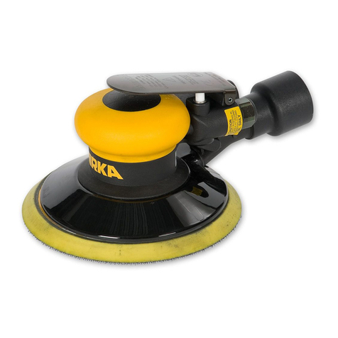
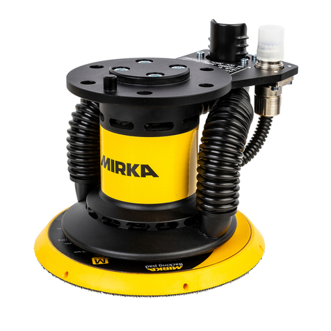
MIRKA ROS2 series User manual


1
.X +/-
NA
RAG
0.5°
10/30/08
PWH
STD TOL
0.05
0.1
XPD0062
P/N
TITLE
DRWN BY / DATE
DUCTION IN PART OR AS A WHOLE WIT HOUT THE WRITTEN
.XX +/-
MATERIAL
NA
TOOLS INC.
X'POLEPRECISION
SEE BOM
PROPERTY OF X'POL E PRECISION TOOLS INC. ANY REPRO-
ANGLES +/-
PROPRIETARY AND CONFIDENTIAL
PERMISSION OF X'POLE PRE CISION TOOLS INC. IS PROHIBITED.
XX/XX +/-
CKD BY / DATE ENG APP / DATE
10/29/08
THE INFORMATION CON TAINED IN THIS DRAWING IS THE SOLE
.XXX +/-
MIRKA 125 & 150 mm (5 & 6 in.) 12,000
RPM TwoHAND™ROS
1DLEIHSTSUDGNIRAEBELDNIPSDNAHowT0452APX07
ADESCRIPTION / DATER REVISION RECORD
-ITEM 49: XPC0146 AND XPC0147 WERE
B
RAG 10/29/08 PWH 10/30/08
-RELEASE FOR PRODUCTION
-ITEMS 69 AND 70 WERE NOT ON
C
RAG 09/03/09 PWH 09/03/09
NOT REMOVED
1DLEIHSTSUDGNIRAEBTNORF1452APX96 1GABMUUCAVAKRIMROFTRESNI4640APX86
RAG 11/04/10 PWH 11/05/10
-ITEMS 68 WAS XPC0109
D
RAG 10/12/10 PWH 10/13/10
YTQNOITPIRCSEDN/PTI 1GNIRGNINIATERLANRETXE0400APX1 1SDLEIHS2-GNIRAEB8X62X011200APX2 1ETALPDNERAER7100BPX3 1YLBMESSAREDNILYCmm0.63Xmm0.05Ø1440APX4 1GNIR-Omm0.2xmm52400APX5 1ROTORDENIHCAMROTOMmm63xmm0.05Ø8110BPX6 5ROTOMmm0.63xmm0.05ØROFENAV5440APX7 2YEKFFURDOOWmm31xmm31400APX8 1ETALPDNETNORF6100BPX9 1SDLEIHS2-GNIRAEB8X82X219100APX01 1GNIR-Omm1.3xmm4.935400APX11 1GNIRKCOL1000APX21
13 XPB0207TwoHAND 125 x 5.0 mm (5 x 3/16 in.) ORBIT ROS AirSHIELD™ SHAFT
BALANCER1
13 XPB0189TwoHAND 125 x10 mm (5 x 3/8 in.) ORBIT ROS AirSHIELD™ SHAFT
BALANCER1
13 XPB0187TwoHAND 150 x 5.0 mm (6 x 3/16 in.) ORBIT ROS AirSHIELD™ SHAFT
BALANCER1
13 XPB0188TwoHAND 150 X10 mm (6 x 3/8 in.) ORBIT ROS AirSHIELD™ SHAFT
BALANCER1
1RETLIF2210APX41 1EVLAVKCEHCLLIBKCUD1210APX51 1RENIATEREVLAV0210APX61 1GNIRGNINIATER).ni23/51(mm9.110900APX71
18 XPA075112 x32 x15.9 DOUBLE ROW ANGULAR CONTACT BEARING -1SEAL 1
1KHT2.0xDO0.22xDI1.21RECAPS7671APX91 1REHSAWELLIVELLEB4201APX02 1ELDNIPS8020BPX12 1GNIRGNINIATER5201APX22 1HCNERWDAPmm422200APX32
24 NA 1 Pad Supplied With Each Tool (Type Determined By Model) 1
2GULPDEDAERHT8M1171APX52
26 XPB039336.0 mm RH PMS 123C YELLOW MIRKA HOUSING W/SIDE HANDLE HOLE 1
1)senihcaMMPR000,01rof(TRESNIRELFFUM2300APX72 1LAESGNISUOHPOT8121APX82 1LAESGNISUOHROTOMmm0.630920BPX92
30 XPA2068 MIRKA 12,000 RPM 5.0 mm (3/16 in.) ORBIT THROTTLE LEVER -TwoHAND 1
30 XPA2069 MIRKA 12,000 RPM 10.0 mm (3/8 in.) ORBIT THROTTLE LEVER -TwoHAND 1
1KCALB-REGNAH0240BPX13 2GNIRRECAPS5681APX23
33 XPB035636.0 mm DIE-CAST MACHINE MOTOR HOUSING W/SIDE HANDLE
MOUNTING STUDS1
1NIPGNIRPSREDNILYC4000APX43 1YLBMESSAMETSEVLAV
5560APX53 1EVEELSEVLAV5100APX63 1TAESEVLAV9000APX73 1EVLAV7000APX83 1GNIRPSEVLAV4100APX93 1YLBMESSALAESENILRIA0370APX04 1TEKSAGTSUAHXE0050APX14 1ELZZONTSUAHXEVGSROTOMmm0.631810BPX24 1ELZZONTSUAHXEVC/VN2810BPX34 3WERCSPACDAEHNOTTUBTEKCOSXEH8X4M4660APX44 1)senihcaMVC&VN(GNIBUTTSUAHXE7150APX54 1PMALCGNIBUT6150APX64 1GNIBUTTELNI1150APX74 1DUORHSVN/REFFUB.ni6/5™DNAHowT3510CPX84 1DUORH
SPL/ELOH-ITLUM.ni5™DNAHowT5410CPX94 1DUORHSPL/ELOH-ITLUM.ni6™DNAHowT8310CPX94 1AKRIM-ELDNAHEDIS1891APX05
51 XPB039436.0 mm LH PMS 123 YELLOW HOUSING W/SIDE HANDLE HOLE 1
5KCALBmm51X0.4MXROTDAEHNOTTUB,WERCS8931APX25 7KCALBmm03X0.4MXROTDAEHNOTTUB,WERCS0341APX35 1GNIR-Omm5.1xmm93400APX45 1LORTNOCDEEPS™DNAHowT3810BPX55 1GNIRGNINIATERLANRETNI9300APX65 1GNIREVITPACTELNI0150APX75 1GNIR-Omm87.1xmm6.790
50APX85 1)senihcaMVC&VN(GNIR-O8260APX95 2)senihcaMVC&VN(RELFFUM6770APX06
61 XPA0731 INLET/EXHAUST END CAP ASSEMBLY FOR NV MACHINES 1
62 XPA1294 INLET/EXHAUST END CAP ASSEMBLY FOR SGV AND CV MACHINES 1
1YLBMESSAGNIHSUBTELNITPN81-4/13100APX36
64 XPA0392Ø1in. VAC HOSE TO Ø1in./28 mm x 1 1/2 in. ADAPTOR COUPLING AND
AIRLINE ASSEM1
1™DNAHowT-LAESESOH)mm82(.ni13260APX56
66 XPA0412 Ø1in. VAC HOSE TO DOUBLE BAG FITTING AND AIRLINE ASSY 1
1GABMUUCAV0110CPX76
ITEM NO. TORQUE SETTINGS N-m (in.-lbs)
12 6.2 - 7.3 (55 - 65)
43 2.4 - 3.4 (21 - 30)
52 3.0 - 3.4 (27 - 30)
53 3.3 - 3.7 (29 - 33)
63 6.8 - 8.1 (60 - 72)
66
46
68
65
TO VACUUM
SYSTEM FOR
CENTRAL
VACUUM
69
1
2
3
4
5
6
7
9
10
11
12
13
14
15
16
17
18
19
20
21
22 23
24
25
26
31
32 33
34
35
64
53
60
8
52
27 28
29
30
41
42
43
44
67
45
47
48
36 37
49
25
50
51
38 39
54 55 56
40
52
57 58 59 61
62
63
53
52
70
Parts Page
D
F
H
C
G
A
E
A
D
B
I
D

2
Parts List
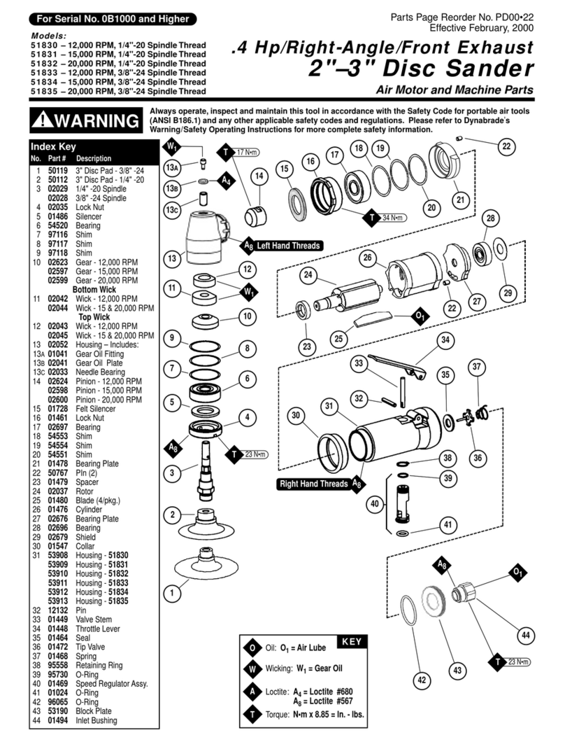
Item No. Part No. Description Qty.
1 MPA0040 RETAININGRING 1
2 MPA0021 BEARING 1
3 MPB0017 REARENDPLATE 1
4 MPA0441 CYLINDER ASSEMBLY 1
5 MPA0042 O-RING 1
6 MPB0118 ROTOR 1
7 MPA0445 VANE 5
8 MPA0041 KEY 2
9 MPB0016 FRONTENDPLATE 1
10 MPA0019 BEARING 1
11 MPA0045 O-RING 1
12 MPA0001 LOCK RING 1
13 MPB0207 125x5.0mm(5x3/16in.)ORBITSHAFTBALANCER 1
MPB0189 125x10mm(5x3/8in.)ORBITSHAFTBALANCER 1
MPB0187 150x5.0mm(6x3/16in.)ORBITSHAFTBALANCER 1
MPB0188 150X10mm(6x3/8in.)ORBITSHAFTBALANCER 1
14 MPA0122 FILTER 1
15 MPA0121 DUCKBILL CHECK VALVE 1
16 MPA0120 VALVERETAINER 1
17 MPA0090 RETAININGRING 1
18 MPA0751 DOUBLE ROW BEARING 1
19 MPA1767 SPACER 1
20 MPA1024 BELLEVILLE WASHER 1
21 MPB0208 SPINDLE 1
22 MPA1025 RETAININGRING 1
23 MPA0022 PAD WRENCH 1
24 NA 1Padsuppliedwitheachtool(typedeterminedbymodel) 1
25 MPA1711 THREADEDPLUG 2
26 MPB0393 RH HOUSING 1
27 MPA0032 MUFFLERINSERT 1
28 MPA1218 TOPHOUSINGSEAL 1
29 MPB0290 MOTORHOUSINGSEAL 1
30 MPA2068 5.0mm(3/16in.)ORBITTHROTTLELEVER 1
MPA2069 10.0mm(3/8in.)ORBITTHROTTLELEVER 1
31 MPB0420 HANGER - BLACK 1
32 MPA1865 SPACER RING 2
33 MPB0356 MOTORHOUSING 1
34 MPA0004 CYLINDER SPRING PIN 1
35 MPA0655 VALVESTEMASSEMBLY 1
36 MPA0015 VALVE SLEEVE 1
37 MPA0009 VALVESEAT 1
38 MPA0007 VALVE 1
39 MPA0014 VALVE SPRING 1
40 MPA0730 AIRLINE SEAL ASSEMBLY 1
41 MPA0500 EXHAUSTGASKET 1
42 MPB0181 DBEXHAUSTNOZZLE(DBmachines) 1
43 MPB0182 NV/CVEXHAUSTNOZZLE(NV&CVmachines) 1
44 MPA0664 SCREW 3
45 MPA0517 EXHAUSTTUBING(NV&CVmachines) 1
46 MPA0516 TUBINGCLAMP(NV&CVmachines) 1
47 MPA0511 INLETTUBING 1
48 MPC0153 125/150 mm (5/6 in.) BUFFER/NV SHROUD 1
49 MPC0145 125mm(5in.)MULTI-HOLE/LPSHROUD 1
MPC0138 150mm(6in.)MULTI-HOLE/LPSHROUD 1
50 MPA1981 SIDE HANDLE - Mirka 1
51 MPB0394 LH HOUSING 1
52 MPA1398 SCREW 5
53 MPA1430 SCREW 7
54 MPA0043 O-RING 1
55 MPB0183 SPEED VALVE 1
56 MPA0039 RETAININGRING 1
57 MPA0510 INLETCAPTIVERING 1
58 MPA0509 O-RING 1
59 MPA0628 O-RING(NV&CVmachines) 1
60 MPA0776 MUFFLER(NV&CVmachines) 2
61 MPA0731 INLET/EXHAUSTENDCAPASSEMBLY(NVmachines) 1
62 MPA1294 INLET/EXHAUSTENDCAPASSEMBLY(DB&CVmachines) 1
63 MPA0013 INLETBUSHINGASSEMBLY 1
64 MPA0392 Ø28mm(1in.)VACUUMHOSETOØ28mm(1in.)x38mm(11/2in.)ADAPTORCOUPLING&AIRLINE
ASSEMBLY (CV machines) 1
65 MPA0623 Ø 28 mm (1 in.) HOSE SEAL (DB machines) 1
66 MPA0412 Ø28mm(1in.)VACUUMHOSETODOUBLEBAGFITTINGANDAIRLINEASSEMBLY(DBmachines) 1
67 MPA0658 VACUUM BAG 1
68 MPA0465 10PACKOFVACUUMBAGINSERTS 1
69 MPA2541 FRONTBEARINGDUSTSHIELD 1
70 MPA2540 TwoHANDSPINDLEBEARINGDUSTSHIELD 1

3
Sander Spare Parts Kits
CMPA2216 Air Inlet Kit
Code: 8994024011
AMPA2214MuferKit
Code: 8994026011 BMPA2186 Spindle Bearing Kit
Code: 8994021811
FMPA2220;RotorVanesandKeyKit
Code: 8994020611
RAG01/31/08 PWH 02/13/08
-RELEASE FOR PRODUCTION
ADESCRIPTION / DATER REVISION RECORD
YTQNOITPIRCSEDN/PTI 2YEKFFURDOOWmm31xmm31400APX1 1ROTORDENIHCAMROTOMmm63xmm0.05Ø8110BPX2 5ROTOMmm0.63xmm0.05ØROFENAV5440APX3
4 XPA1887 LABEL FOR AirVANTAGE ROTOR, VANES AND KEYS KIT - 36.0 MM MOTOR 1
1GABEPAN5
01/31/08 PWH
02/13/08
REVISED 12/19
KEYS KIT -36.0 MM MOTOR
XPA1881
P/N
RAG
NA
NA
TITLE
DRWN BY / DATE
MATERIAL
PROPRIETARY AND CONFIDENTIAL
DUCTION IN PART OR ASA WHOLE WITHOUT THE WRITTEN
.XX +/-
PERMISSION OF X'POLE PRECISION TOOLS INC. IS PROHIBITED.
0.5°
X'POLEPRECISION
/05
PROPERTY OF X'POLE PRECISION TOOLS INC. ANY REPRO-
ANGLES +/-
0.1
0.05
CKD BY / DATE ENG APP / DATE
STD TOL
.X +/- XX/XX +/-
TOOLS INC.
THE INFORMATION CONTAINEDIN THIS DRAWING IS THE SOLE
.XXX +/-
AirVANTAGE™ ROTOR, VANES AND
SEE BOM
REVISION RECORD
R DESCRIPTION / DATE
A-RELEASE FOR PRODUCTION
RAG01/30/08 PWH 02/13/08
YTQNOITPIRCSEDN/PTI 2RELFFUM6770APX1 1)senihcaMMPR000,01rof(TRESNIRELFFUM2300APX2 1TIKRELFFUMMPR000,21EGATNAVriAROFLEBAL3881APX3 1GABEPAN4
RAG
01/30/08 PWH
02/13/08
REVISED 12/19
- 2 HAND
XPA1877
TOOLS INC.
NA
0.05
P/N
TITLE
DRWN BY / DATE
MATERIAL
.XX +/-
DUCTION IN PART OR ASA WHOLE WITHOUT THE WRITTEN
PROPRIETARY AND CONFIDENTIAL
NA
0.5°
X'POLEPRECISION
/05
PROPERTY OF X'POLE PRECISION TOOLS INC. ANY REPRO-
ANGLES +/-
0.1
PERMISSION OF X'POLE PRECISION TOOLS INC. IS PROHIBITED.
CKD BY / DATE ENG APP / DATE
STD TOL
.X +/- XX/XX +/-
THE INFORMATION CONTAINEDIN THIS DRAWING IS THE SOLE
.XXX +/-
AirVANTAGE™ 12,000 RPM MUFFLER KIT
SEE BOM
EMPA2218 Speed Valve Kit
Code: 8994025511
GMPA2222 Vacuum Endcap Kit
Code: 8994026711
HMPA0993 Lock Ring and O-ring Kit
Code: 8993007911
DMPA0799 Endplate Bearing Kit
Code: 8993019811
IMPA2531 Housing Seal Kit
Code: 8994012911

20
Mirka 125 mm & 150 mm
Zweihand-Exzenterschleifer Druckluft
12.000 U/min
Fabrikant/Lieferant
Mirka Ltd.
66850 Jeppo, Finland
Tel:+358207602111
Fax: +358 20 760 2290
Erforderliche Persönliche Schutzausrüstung
Schutzbrille Atemschutzmaske
Sicherheitshandschuhe Gehörschutz
Empfohlene Größe der
Luftleitung
Ø10 mm
Empfohlene Maximale
Schlauchlänge
8 Meter
Luftdruck
Maximaler Arbeitsdruck 6.2 bar 90 psig
Empfohlene Minimum k.A. k.A
Gebrauchsanweisung
Inhalt: Bitte lesen und beachten;
BestimmungsgemäßeVerwendungdesGerätes;Arbeitsplatz;
Inbetriebnahme;Bedienungsanleitung;Tabellenfür
Produktkonguration/Spezikationen;Explosionszeichnung;
Ersatzteilliste;ErsatzteilsetsfürExzenterschleifmaschine;
Störungsbehebung
Konformitätserklärung
Mirka Ltd. 66850 Jepua, Finnland
erklärtunsereeinzigeVerantwortungdassdieProdukte125mm&150mmZweihand-ExzenterschleiferDruckluft12.000U/min
(Siehe“Produkt-Konguration/Spezikationen”TafelfürspezielleModelle)
aufwelchesichdieseErklärungbezieht,konformmitdenfolgendenGrundnormenodersonstigennormativenDokumentenENISO
15744:2008. Den Bestimmungen 89/392/EEC wie korrigiert von 91/368/EEC
&93/44/EEC93/68/EECRichtlinienundbestätigendeRichtlinien2006/42/ECfolgend.
OrtundDatum Unternehmen StefanSjöberg,CEO
Wichtig
Lesen Sie diese Instruktionen
sorgfältig,bevorSiedieMas-
chine in Betrieb nehmen, warten
oder reparieren. Bewahren Sie
dieInstruktionensorgfältigauf.
Jeppo 22.01.2015
Übersetzung der Original-Anleitung

21
1) BittelesenSiedieBedienungsanleitung,bevorSiedasGerätinBetriebnehmen.AlleBenutzermüssenindieHandhabungdes
GeräteseingewiesenwerdenunddieSicherheitsbestimmungenkennen.AlleWartungs-undReparaturarbeitendürfennurvonquali-
ziertemPersonalausgeführtwerden.
2) UnterbrechenSiedieDruckluftzufuhrdesGerätes.
WählenSieeinepassendeSchleifscheibeundbefesti-
gen Sie diese in der Mitte des Schleiftellers.
3) TragenSieimmerdiegeforderteSchutzausrüstung,
wennSiedasGerätbenutzen
4) BeimSchleifenimmerdasGerätzuerstaufdie
Arbeitsächeanbringen,bevordasGerätgestartet
wird.EbensoimmerdasGerätvonderArbeitsäche
wegnehmen,bevordasGerätgestopptwird.Dies
verhinderteineAushöhlungderOberächedurcheine
Übergeschwindigkeit der Schleifscheibe.
5) Immer die Druckluftzufuhr zur Schleifmaschine unter-
brechen, bevor Sie eine Schleifscheibe wechseln oder
sonstigeArbeitenamSchleiftellerausführen.
6) Immerfüreinenfesten/sicherenStandsorgenund
rechnen Sie mit einer Fluchtreaktion der Maschine.
7) Nur Original Mirka-Ersatzteile verwenden.
8) DaszuschleifendeMaterialmussgutxiertsein,um
ein„wandern“zuverhindern.
9) DenSchlauchunddieAnschlüsseregelmäßigaufAb-
nutzungkontrollieren.DasGerätniemalsamSchlauch
tragen; es wird empfohlen die Druckluftzufuhr zu
unterbrechen,wenndasGerätgetragenwird.
10)Staubkannsehrfeuergefährlichsein.DerStaub-
fangsacksolltetäglichgereinigtoderausgetauscht
werden. Die Reinigung bzw. der Austausch des Staub-
fangsackssorgtauchfüroptimaleLeistung.
11) DerangegebeneHöchstluftdruckdarfnichtüberschrittenwerden.Sicherheitsausrüstungsollwieempfohlenverwendetwerden.
12)DasGeräthatkeineelektrischeIsolierung.BenutzenSieesnicht,wenndieGefahrbesteht,dassesbeimArbeitenzueinemKontakt
mitelektrischemStrom,Gasleitungen,Wasserleitungenetckommenkann.ÜberprüfenSiedieArbeitsäche,bevorSiemitderArbeit
beginnen.
13)StellenSiesicher,dassichHaare,Putzlappen,KleidungundähnlichesDingenichtindenbeweglichenTeilenderMaschineverfangen
können.
14)DieHändesorgfältigvondendrehendenTeilenfernhalten,wenndieMaschineinBetriebist.
15)ImFalleeinerStörungoderFehlfunktionmussdasGerätsofortaußerBetriebgenommenwerden.
16)DasGerätdarfnichtfreidrehen,ohnedassmanMaßnahmengetroffenhat,dassPersonenundObjektenichtgefährdetsind,fallssich
eineSchleifscheibeoderderSchleiftellerlöst.
1)GeneralIndustrySafety&HealthRegulations,Part1910,
OSHA2206,erhältlichvon:Sup’tofDocuments;Government
PrintingOfce;WashingtonDC20402
2)SafetyCodeforPortableAirTools,ANSIB186.1erhältlichvon:
AmericanNationalStandardsInstitute,Inc.;1430Broadway;
New York, NY 10018
3) Nationale und lokale Vorschriften.
DieseSchleifmaschineisthergestelltzumSchleifenallerTypen
von Materialen, d.h. Metalle, Holz, Stein, Plastik, etc. mittels Ge-
brauchvonSchleifpapier,dasfürdiesenZweckentwickeltwurde.
DieseSchleifmaschinedarfnichtfürirgendwelcheandereZwecke
gebraucht werden, ohne beim Hersteller oder den autorisierten
Liefereranten des Herstellers nachzufragen. Schleifteller deren
Arbeitsgeschwindigkeitgeringerals12.000U/min.ist,dürfennicht
verwendet werden.
DasGerätwirdalshandgehalteneMaschinebedient.Eswird
empfohlen,immerauffestemBodenzustehen,wenndasGerät
in Betrieb ist. Es kann in jeder Position bedient werden, der
Betreiber muss aber in einer sicheren Position stehen und sich
auchdarüberbewusstsein,dassdieMaschineein„Drehmoment“
entwickelnkann.(Ausbrechen).DenAbschnitt„Bedienungsanlei-
tung“sorgfältiglesen.
Hinweis, bitte lesen und beachten: Inbetriebnahme
Bedienungsanleitung
Benutzen Sie eine saubere geschmierte Luftversorgung, die der
Maschine einen gemessenen Luftdruck von 6.2 bar /90 PSI unter
Vollast geben kann. Es wird empfohlen, einen zugelassenen
LuftschlauchvonØ10mm(3/8“)x8mmaximalerLängezube-
nutzen.Eswirdempfohlen,dasGerätmitderDruckluftversorgung
so zu verbinden wie auf Bild 1 gezeigt.
VerbindenSiedasGerätnichtmitderDruckluftversorgung,ohne
ein leicht erreichbares und einfach zu bedienendes Absperrventil
angebracht zu haben. Die Druckluft muss geschmiert sein. Es
wird dringend empfohlen, ein FRL, d.h. ein kombinierter Filter,
Regler und Schmierer zu gebrauchen, wie auf Bild 1 gezeigt.
Diesersorgtdafür,dassdasGerätsaubere,geschmierteLuftmit
dem richtigen Druck bekommt. Weitere Informationen bekommen
SievonIhremHändler.OhneeinFRLmussdasGerätmanuell
geschmiert werden.
UmdasGerätmanuellzuschmieren,nehmenSiedenDruck-
luftschlauchabundlassenSie2-3Tropfeneinespneumatischen
Motorenschmieröls,wiez.B.FujiKosanFK-20,MobilALMO
525oderShellTORCULA®32indasSchlauchende(Einlass)
derMaschinekommen.DasGerätwiederandieDruckluft
anschließenundlangsameinigeSekundenlaufenlassen,sodass
dieLuftdasÖlverteilenkann.FallsdasGerätöftersgebraucht
wird,mussestäglichgeschmiertwerden,jedochspätestens
dann, wenn es langsamer wird oder Kraft verliert.
Es wird empfohlen, das der Betriebsluftdruck 6.2 bar/90 PSI
beträgt.DasGerätkannmitniedrigerenDrückenarbeiten,aber
niemalshöheralsmit6.2bar/90PSI.
Arbeitsplätze
BestimmungsgemäßeVerwendung
Geschlossenes Ringleistungssystem
in Richtung des Luftstroms geneigt
Drainageabfluss
Kugelventil
zur
Werkzeugstation
Filter
Ablassventil
Regler
Schmierstoffgeber
Kugel-
ventil
Kugelventil Luftstrom
Lufttrockner
Luftverdichter
und Tank
Luftschlauch
zur Kupplung
am oder in der
Nähe des Werkzeugs

22
SpezikationenkönnenzujederZeitohnevorausgegangeneAnkündigunggeändertwerden.
*DieWerteindenTabellenstammenvonLaborprüfungeninÜbereinstimmungmitangegebenenStandardsundGrundnormenundsindnicht
füreineRisikoschätzungausreichend.WerteaufeinembestimmtenArbeitsplatzkönnenhöheralsdieerklärtenWertesein.Dietatsächlichen
WerteunddieGrößevonRisikooderVerletzung,dieeinePersonerlebt,sindfürjedeSituationeinmaligundsindvonderUmgebung,vonder
ArtundWeisewieeinePersonarbeitet,mitwelchemMaterial,vomArbeitsplatzsowievonderArbeitsdauerundderphysischenKonstitutiondes
Benutzersabhängig.Mirka,Ltd.kannnichtverantwortlichgemachtwerdenfürdieeventuellenKonsequenzen,fallsdeklarierteWertegebraucht
werden,stattdertatsächlichauftretendenWertefürjedeeinzelneGefährdungsabschätzung.
WeitereInformationenüberArbeitsgesundheitund-sicherheitsindvondenfolgendenWebseitenerhältlich:
https://osha.europa.eu/en (Europa)
http://www.osha.gov (USA)
Produktkonguration/TechnischeDaten:Druckluft-Exzenterschleifermit12.000U/min
Exzenter Absaugung
Größe
Schleif-
blatt )mm(
Modell-nr.
Netto-
gewicht
Produkt
)kg(
Höhe )mm( Länge
)mm( *Geräusch-
pegel dBA
Leis-
tung
Watt
)HP(
Luft-verbrauch
LPM )scfm(
*Vibra-
tions-stärke
m/s2
*Unsicher-
heitsfaktor
K
m/s2
5,0 mm
(3/16 in.)
Ohne NV
125 (5) ROS2-550NV 1,18 (2,60) 112,6 (4,43) 273,9
(10,78) 85 343
(0,46) 594 (21) 2,7 1,4
150 (6) ROS2-650NV 1,23 (2,71) 112,6 (4,43) 285,2
(11,23) 83 343
(0,46) 594 (21) 3,8 1,9
Zentrale
Absaugung
125 (5) ROS2-550CV 1,21 (2,66) 112,6 (4,43) 314,5
(12,38) 84 343
(0,46) 594 (21) 3,2 1,6
150 (6) ROS2-650CV 1,27 (2,80) 112,6 (4,43) 325,8
(12,83) 85 343
(0,46) 594 (21) 3,0 1,5
Selbst
erzeugte
Absaugung
125 (5) ROS2-550DB 1,20 (2,65) 112,6 (4,43) 314,5
(12,38) 92 343
(0,46) 594 (21) 3,4 1,7
150 (6) ROS2-650DB 1,26 (2,78) 112,6 (4,43) 325,8
(12,83) 88 343
(0,46) 594 (21) 3,6 1,8
10,0 mm
(3/8 in.)
Ohne NV
125 (5) ROS2-510NV 1,23 (2,70) 112,6 (4,43) 276,4
(10,88) 85 343
(0,46) 594 (21) 3,4 1,7
150 (6) ROS2-610NV 1,27 (2,81) 112,6 (4,43) 287,7
(11,33) 87 343
(0,46) 594 (21) 3,3 1,7
Zentrale
Absaugung
125 (5) ROS2-510CV 1,25 (2,76) 112,6 (4,43) 317,0
(12,48) 83 343
(0,46) 594 (21) 3,5 1,8
150 (6) ROS2-610CV 1,32 (2,90) 112,6 (4,43) 328,3
(12,93) 81 343
(0,46) 594 (21) 3,4 1,7
Selbst
erzeugte
Absaugung
125 (5) ROS2-510DB 1,25 (2,74) 112,6 (4,43) 317,0
(12,48) 85 343
(0,46) 594 (21) 3,1 1,6
150 (6) ROS2-610DB 1,31 (2,88) 112,6 (4,43) 328,3
(12,93) 90 343
(0,46) 594 (21) 3,3 1,7
DerSchalltestwurdegemäßENISO15744:2008:MessungderGeräuschemissionenvonhandgehaltenennicht-elektrischenKraftgeräten
ausgeführt.
DerSchwingungstestwurdeausgeführtgemäßEN28662-1.HandgehaltenetragbareKraftgeräte–SchwingungsmessungbamGriff.Teil1:
AllgemeinesundEN8662-8,1997.Handgehaltene,tragbareKraftgeräte–SchwingungsmessungamGriff.Teil8:Poliermaschinenundrotierende,
außermittigeundexzenterSchleifmaschinen.

23
STÖRUNGSBEHEBUNG
Symptom MöglicheUrsache Lösung
Niedrige Kraft und/oder niedrige
freie Drehzahl
UngenügenderLuftdruck Den Luftdruck am Einlass der Schleifmaschine
kontrollieren,währenddasGerätmitfreierDrehzahl
läuft.Ermuss6.2Bar(90psig/620kPa)betragen.
Verstopfte(r)Schalldämpfer Indem“DemontagevonGehäuse”-Abschnittwird
dargestelltwiemandenSchalldämpferausbaut.
DerSchalldämpfer(TeilNummer60)kannmiteiner
sauberen,passendenReinigungslösunggespült
werden, bis alle Verschmutzungen und Verstop-
fungenentferntsind.FallsderSchalldämpfernicht
ordnungsgemäßgereinigtwerdenkann,musser
ausgetauschtwerden.MitdemSchalldämpferein-
satz,ersetzen(wirdimAbschnitt„Montagedes
Gehäuses“beschrieben.
VerstopfterLufteinlasslter DenLufteinlassltermiteinersauberen,geeigneten
Lösungreinigen.FallsderLufteinlasslternicht
sauber wird, muss er ausgetauscht werden.
EinodermehrereBlätterabgenutztoder
gebrochen EinkomplettesSetvonneuenBlätterninstallieren
(füreineguteWirkungmüssenalleBlätterausge-
tauschtwerden).AlleBlättermiteinemQualitätsöl
fürpneumatischeGerätebestreichen.Beschreibung
indenAbschnitten„DemontagedesMotors“und
„MontagedesMotors“.
Luft-LeckageimMotorgehäuse,zuerkennen
anüberhöhtemLuftverbrauchundniedriger
Drehzahl.
Kontrollieren Sie ob der Motor richtig justiert ist und
der Verschlussring ordentlich sitzt. Kontrollieren Sie
obderO-RingindemVerschlussringnutebeschä-
digt ist. Den Motor demontieren und wieder montie-
ren.BeschreibungindenAbschnitten„Demontage
desMotors“und„MontagedesMotors“.
TeiledesMotorsabgenutzt DenMotorüberholen.EinautorisiertesMirkaSer-
vice Center kontaktieren.
Abgenutzte oder gebrochene Spindellager Die abgenutzten oder gebrochenen Lager
austauschen. Beschreibung in den Abschnitten
“DemontagevonAchsenstabilisatorundSpindel”
und“Spindellager,AirSHIELD™undMontagevon
Achsenstabilisator”.
Luft entweicht aus Geschwin-
digkeitsregelung und/oder
Ventilschaft.
Ventilschaft, Ventil oder Ventilsitz schmutzig,
gebrochen oder verbogen. AbgenutzteoderbeschädigteTeiledemontieren,
prüfenundersetzen.BeschreibunginSchritt2und
3in“DemontagevonGehäuse”undSchritt2und3
in“MontagedesGehäuses”.
Starke Vibrationen oder un-
ruhiger Lauf
Falsche Schleifscheibe NurSchleifscheibenvonrichtigerGrößeund
Gewicht,diefürdieMaschinehergestelltsind,
gebrauchen.
Gebrauch von Schleifscheiben Nur Schleifscheiben und/oder Interface gebrauchen,
diefürdieMaschinehergestelltsind.Nichtsander
Schleifmaschinefestmachen,wasnichtfürden
Gebrauch mit Scheibe und Schleifmaschine speziell
hergestellt wurde.
Unzureichende Schmierung oder Versch-
mutzung durch Aufbau von Fremdstoffen Die Schleifmaschine demontieren und mit einer
geeignetenReinigungslösungreinigen.DieSchleif-
maschinemontieren.(Beschreibungin“Wartung-
shandbuchl”)
Abgenutzte oder gebrochene Motorlager Der/die abgenutzte(n) oder gebrochene(n) Lager
ersetzen.BeschreibungindenAbschnitten„Demon-
tagedesMotors“und„MontagedesMotors“.
Bei Maschinen mit Eigenabsaugung besteht
dieMöglichkeit,dasderdaseinUnterdruck
entsteht,wenneineebeneOberächege-
schliffen wird. Dies bewirkt dass die Scheibe
aufderSchleifächehängenbleibt.
Bei Maschinen mit Eigenabsaugung eine
zusätzlicheUnterlegscheibezurScheibenspin-
delmontieren,umdenZwischenraumzwischen
Scheibe und Mantel zu erweitern. Bei Maschinen
mitZentralabsaugungdurchdasVakuumsystemre-
duzierenund/odereinezusätzlicheUnterlegscheibe
zur Scheibe montieren.
DOC A1983 Rev 05/16/17

28
Mirka 12,000 rpm Two-handed
125 mm )5 in.( & 150 mm )6 in.(
RANDOM ORBITAL SANDERS
Manufacturer/Supplier
Mirka Ltd.
66850 Jeppo, Finland
Tel:+358207602111
Fax: +358 20 760 2290
Required Personal Safety Equipment
SafetyGlasses BreathingMasks
SafetyGloves EarProtection
Recommended Airline
Size - Minimum
10 mm 3/8 in.
Recommended Maximum
Hose Length
8 metres 25 feet
Air Pressure
Maximum Working Pressure 6.2 bar 90 psig
Recommended Minimum NA NA
Operator Instructions
Includes–PartsPage,PartsList,SanderSparePartsKits,
PleaseReadandComply,ProperUseofTool,WorkStations,
PuttingtheToolIntoService,OperatingInstructions,Product
Conguration/SpecicationsTables.
Declarationofconformity
Mirka Ltd.
66850 Jeppo, Finland
declareonoursoleresponsibilitythattheproducts125mm(5in.)and150mm(6in.)12,000rpmTwo-handed Random Orbital Sanders
(see“ProductConguration/Specications”tableforparticularmodel)towhichthisdeclarationrelatesisinconformitywiththefollowing
standard(s)orothernormativedocument(s)ENISO15744:2008.Followingtheprovisionsof89/392/EECasamendedby91/368/EEC&
93/44/EEC 93/68/EEC Directives and
consolidating Directive 2006/42/EC
Place and date of issue Company Stefan Sjöberg, CEO
Important
Read these instructions care-
fullybeforeinstalling,operating,
servicing or repairing this tool.
Keep these instructions in a safe
accessible location.
Original Instructions
Jeppo 22.01.2015

29
Closed Loop Pipe System
Sloped in the direction of air flow
Drain Leg
Ball Valve
To Tool Station
Filter
Drain Valve
Regulator
Lubricator
Ball
Valve
Ball Valve Air Flow
Air Dryer
Air Compressor
and Tank
Air Hose
To Coupler
at or near Tool
PleaseReadandComplywith PuttingtheToolintoService
Operating Instructions
Work Stations
ProperUseofTool
1)GeneralIndustrySafety&HealthRegulations,Part1910,
OSHA 2206, available from: Superintendent of Documents;
GovernmentPrintingOfce;WashingtonDC20402
2)SafetyCodeforPortableAirTools,ANSIB186.1availablefrom:
AmericanNationalStandardsInstitute,Inc.;1430Broadway;
New York, New York 10018
3) State and Local Regulations.
Thistoolisdesignedforsandingalltypesofmaterialsi.e.metals,
wood, stone, plastics, etc. using abrasive designed for this pur-
pose.Donotusethistoolforanyotherpurposethanthatspeci-
edwithoutconsultingthemanufacturerorthemanufacturer’s
authorized supplier. Do not use backing pads that have a working
speed less than 12,000 rpm free speed.
Thetoolisintendedtobeoperatedasahand-heldtool.Itis
alwaysrecommendedthatthetoolbeusedwhenstandingona
solidoor.Itcanbeusedinanypositionbutbeforeanysuchuse,
theoperatormustbeinasecurepositionhavingarmgripand
footingandbeawarethatthetoolcandevelopatorquereaction.
Seethesection“OperatingInstructions”.
Useacleanlubricatedairsupplythatwillgiveameasuredair
pressure at the tool of 6.2 bar (90 psig) bar when the tool is run-
ningwiththeleverfullydepressed.Itisrecommendedtousean
approved 10 mm (3/8 in.) x 8 m (25 ft) maximum length airline. It
isrecommendedthatthetoolbeconnectedtotheairsupplyas
shown in Figure 1.
Donotconnectthetooltotheairlinesystemwithoutincorporating
aneasytoreachandoperateairshutoffvalve.Theairsupply
shouldbelubricated.Itisstronglyrecommendedthatanairlter,
regulator and lubricator (FRL) be used as shown in Figure 1 as
thiswillsupplyclean,lubricatedairatthecorrectpressureto
thetool.Detailsofsuchequipmentcanbeobtainedfromyour
supplier.Ifsuchequipmentisnotusedthenthetoolshouldbe
manuallylubricated.
Tomanuallylubricatethetool,disconnecttheairlineandput2to
3 drops of suitable pneumatic motor lubricating oil such as Fuji
KosanFK-20,MobilALMO525orShellTORCULA®32intothe
hoseend(inlet)ofthemachine.Reconnecttooltotheairsupply
andruntoolslowlyforafewsecondstoallowairtocirculatethe
oil.Ifthetoolisusedfrequently,lubricateitonadailybasisor
lubricate it if the tool starts to slow or lose power.
It is recommended that the air pressure at the tool is 6.2 bar (90
psig)whilethetoolisrunning.Thetoolcanrunatlowerpressures
but never higher than 6.2 bar (90 psig).
1) Readallinstructionsbeforeusingthistool.Alloperatorsmustbefullytrainedinits
useandawareofthesesafetyrules.Allservicingandrepairsmustbecarriedout
bytrainedpersonnel.
2) Makesurethetoolisdisconnectedfromtheairsupply.Selectasuitableabrasive
andsecureittothebackingpad.Takecaretocentretheabrasiveonthebacking
pad.
3) Alwayswearappropriatesafetyequipmentwhenusingthistool.
4) Whensandingalwaysplacethetoolontheworkthenstart
thetool.Alwaysremovethetoolfromtheworkbeforestop-
ping.Thiswillpreventgougingoftheworkduetoexcess
speed of the abrasive.
5) Alwaysdisconnecttheairsupplyfromthesanderbefore
tting,adjustingorremovingtheabrasiveorbackingpad.
6) Alwaysadoptarmfootingand/orpositionandbeaware
ofthetorquereactiondevelopedbythesander.
7) Useonlycorrectspareparts.
8) Alwaysensurethatthematerialtobesandedisrmlyxed
to prevent its movement.
9) Checkhoseandttingsregularlyforwear.Donotcarrythe
toolbyitshose;alwaysbecarefultopreventthetoolfrom
beingstartedwhencarryingthetoolwiththeairsupply
connected.
10)Dustcanbehighlycombustible.Thevacuumdustcollec-
tionbagshouldbecleanedorreplaceddailyorwhenbag
reaches half full or 2.3 kg (5 lbs.). Cleaning or replacing the
bag also assures optimum performance.
11) Do not exceed maximum recommended air pressure. Use
safetyequipmentasrecommended.
12)Thetoolisnotelectricallyinsulated.Donotusewhere
thereisapossibilityofcomingintocontactwithlive
electricity,gaspipes,waterpipes,etc.Checktheareaof
operation before use.
13)Takecaretoavoidentanglementofthemovingpartsofthetoolwithclothing,ties,
hair,cleaningrags,etc.Ifentangled,itwillcausethebodytobepulledtowardsthe
workandmovingpartsofthemachineandcanbeverydangerous.
14) Keep hands clear of the spinning pad during use.
15)Ifthetoolappearstomalfunction,removefromuseimmediatelyandarrangefor
service and repair.
16)Donotallowthetooltofreespeedwithouttakingprecautionstoprotectanyper-
sons or objects from the loss of the abrasive or pad.

30
ProductConguration/Specications:12,000rpmRandomOrbitalSander
Orbit Vacuum
Type
Pad
Size mm
)inch(
Model
Number
Product Net
Weight kg
)pounds(
Height
mm )inch(
Length
mm )inch(
*Noise
Level
dBA
Power
watts
)HP(
Air Consumption
lpm )scfm(
*Vibration
Level m/s2*Uncertainty
K m/s2
5.0 mm
(3/16 in.)
Non-Vac 125 (5) ROS2-550NV 1.18 (2.60) 112.6
(4.43) 273.9
(10.78) 85 343
(0.46) 594 (21) 2.7 1.4
150 (6) ROS2-650NV 1.23 (2.71) 112.6
(4.43) 285.2
(11.23) 83 343
(0.46) 594 (21) 3.8 1.9
Central
Vacuum
125 (5) ROS2-550CV 1.21 (2.67) 112.6
(4.43) 314.5
(12.38) 84 343
(0.46) 594 (21) 3.2 1.6
150 (6) ROS2-650CV 1.27 (2.80) 112.6
(4.43) 325.8
(12.83) 85 343
(0.46) 594 (21) 3.0 1.5
Self-Gen.
Vacuum
125 (5) ROS2-550DB 1.20 (2.65) 112.6
(4.43) 314.5
(12.38) 92 343
(0.46) 594 (21) 3.4 1.7
150 (6) ROS2-650DB 1.26 (2.78) 112.6
(4.43) 325.8
(12.83) 88 343
(0.46) 594 (21) 3.6 1.8
10.0 mm
(3/8 in.)
Non-Vac 125 (5) ROS2-510NV 1.23 (2.70) 112.6
(4.43) 276.4
(10.88) 85 343
(0.46) 594 (21) 3.4 1.7
150 (6) ROS2-610NV 1.27 (2.81) 112.6
(4.43) 287.7
(11.3) 87 343
(0.46) 594 (21) 3.3 1.7
Central
Vacuum
125 (5) ROS2-510CV 1.25 (2.76) 112.6
(4.43) 317.0
(12.48) 83 343
(0.46) 594 (21) 3.5 1.8
150 (6) ROS2-610CV 1.2 (2.90) 112.6
(4.43) 328.3
(12.93) 81 343
(0.46) 594 (21) 3.4 1.7
Self-Gen.
Vacuum
125 (5) ROS2-510DB 1.25 (2.74) 112.6
(4.43) 317.0
(12.48) 85 343
(0.46) 594 (21) 3.1 1.6
150 (6) ROS2-610DB 1.1 (2.88) 112.6
(4.43) 328.3
(12.93) 90 343
(0.46) 594 (21) 3.3 1.7
ThenoisetestiscarriedoutinaccordancewithENISO15744:2008-Hand-heldnon-electricpowertools–Noisemeasurementcode–
Engineering method (grade 2).
ThevibrationtestiscarriedoutinaccordancewithEN28662-1Hand-heldportablepowertools–Measurementofvibrationatthehandle.
Part1:GeneralandEN8662-8,1997Hand-heldportablepowertools–Measurementofvibrationatthehandle.Part8:Polishersandrotary,
orbital and random orbital sanders.
Specicationssubjecttochangewithoutpriornotice.
*Thevaluesstatedinthetablearefromlaboratorytestinginconformitywithstatedcodesandstandardsandarenotsufcientforrisk
evaluation.Valuesmeasuredinaparticularworkplacemaybedifferentthanthedeclaredvalues.Theactualexposurevaluesand
amountofriskorharmexperiencedtoanindividualisuniquetoeachsituationanddependsuponthesurroundingenvironment,theway
inwhichtheindividualworks,theparticularmaterialbeingworked,workstationdesignaswellasupontheexposuretimeandthephysi-
calconditionoftheuser.Mirka,Ltd.cannotbeheldresponsiblefortheconsequencesofusingdeclaredvaluesinsteadofactualexposure
valuesforanyindividualriskassessment.
Furtheroccupationalhealthandsafetyinformationcanbeobtainedfromthefollowingwebsites:
https://osha.europa.eu/en (Europe)
http://www.osha.gov (USA)

31
TroubleshootingGuide
Symptom Possible Cause Solution
Low power and/or low free
speed.
Insufcientairpressure. Check air line pressure at the Inlet of the Sander
while the tool is running at free speed. It must be
6.2 Bar (90 psig/620 kPa).
CloggedMufer(s). Seethe“HousingDisassembly”sectionforMufer
removal.TheItem60Mufercanbeback-ushed
with a clean, suitable cleaning solution until all con-
taminants and obstructions have been removed.
IftheMufercannotbeproperlycleanedthen
replaceit.(Seethe“HousingAssembly”section).
Plugged Inlet Screen. Clean the Inlet Screen with a clean, suitable
cleaning solution. If Screen does not come clean
replace it.
One or more worn or broken vanes. Install a complete set of new Vanes (all vanes must
be replaced for proper operation). Coat all vanes
withqualitypneumatictooloil.See“MotorDisas-
sembly”and“MotorAssembly”.
Internal air leakage in the Motor Housing
indicatedbyhigherthannormalaircon-
sumption and lower than normal speed.
Check for proper Motor alignment and Lock Ring
engagement. Check for damaged O-Ring in
LockRinggroove.RemoveMotorAssemblyand
re-installtheMotorAssembly.See“MotorDisas-
sembly”and“MotorAssembly”.
Motor parts worn. Overhaul Motor. Contact authorized Mirka Service
Center.
Worn or broken Spindle Bearings. ReplacethewornorbrokenBearings.See“Shaft
BalancerandSpindleDisassembly”and“Spindle
Bearings, AirSHIELD™ and Shaft Balancer As-
sembly”.
Air leakage through the Speed
Control and/or Valve Stem.
Dirty,brokenorbentValveSpring,Valve
or Valve Seat. Disassemble, inspect and replace worn or dam-
agedparts.Seesteps2and3in“HousingDisas-
sembly”andsteps2and3in“HousingAssembly”.
Vibration/rough operation.
Incorrect Pad. OnlyusePadsizesandweightsdesignedforthe
machine.
Addition of interface pad or other material. Onlyuseabrasiveand/orinterfacedesignedfor
themachine.DonotattachanythingtotheSander
Padfacethatwasnotspecicallydesignedtobe
used with the Pad and Sander.
Improper lubrication or buildup of foreign
debris. Disassemble the Sander and clean in a suitable
cleaning solution. Assemble the Sander. (See
“ServiceManual”.)
Worn or broken Rear or Front Motor
Bearing(s) ReplacethewornorbrokenBearings.See“Motor
Disassembly”and“MotorAssembly”.
For vacuum machines it is possible to
have too much vacuum while sanding on a
atsurfacecausingthepadtosticktothe
sanding surface.
For DB machines add extra washer(s) to the pad
spindle to increase the gap between the pad and
shroud. For CV machines reduce vacuum through
thevacuumsystemand/oraddextrawasher(s)
to the pad.
DOC A1983 Rev 05/16/17

MIRKA LTD
Finland
Brazil Mirka Brasil Ltda.
Canada Mirka Canada Inc.
China Mirka Trading Shanghai Co., Ltd
Finland & Baltics Mirka Ltd
France Mirka France Sarl
Germany Mirka GmbH
India Mirka India Pvt Ltd
Italy Mirka Italia s.r.l.
Mexico Mirka Mexicana S.A. Of C.V
Russia Mirka Rus LLC
Singapore Mirka Asia Pacific Pte Ltd
Spain KWH Mirka Ibérica S.A.U.
Sweden Mirka Scandinavia AB
Turkey Mirka Turkey Zımpara Ltd Şirketi
United Kingdom Mirka (UK) Ltd
United Arab Emirates Mirka Middle East FZCO
USA Mirka USA Inc.
For contact information,
please visit www.mirka.com
© Mirka Ltd • 03/2017
Other manuals for ROS2 series
2
Table of contents
Languages:
Other MIRKA Sander manuals

MIRKA
MIRKA DEOS 353X User manual

MIRKA
MIRKA AIROS User manual

MIRKA
MIRKA RP Series User manual

MIRKA
MIRKA Mirka ROS series User manual

MIRKA
MIRKA DEOS 353CV User manual

MIRKA
MIRKA Mirka ROS series User manual

MIRKA
MIRKA AIROS User manual

MIRKA
MIRKA PROS User manual

MIRKA
MIRKA PBS 10NV User manual

MIRKA
MIRKA CEROS625CV User manual

MIRKA
MIRKA CEROS680CV User manual

MIRKA
MIRKA LEROS-S 950CV User manual

MIRKA
MIRKA 8 Operating instructions

MIRKA
MIRKA OS 343CV User manual

MIRKA
MIRKA Mirka ROS series User manual

MIRKA
MIRKA DEROS MID65020US User manual

MIRKA
MIRKA AROP-B 312NV User manual

MIRKA
MIRKA PROS 550CV User manual

MIRKA
MIRKA Miro 955 User manual

MIRKA
MIRKA ROS325NV User manual