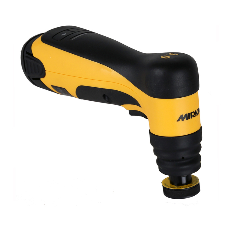
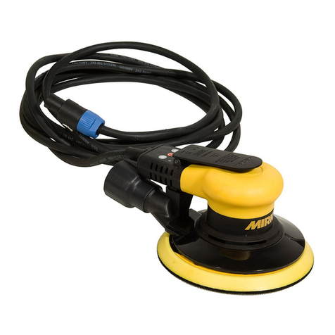
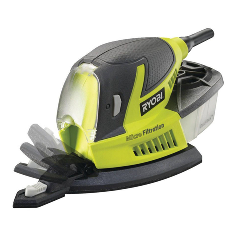
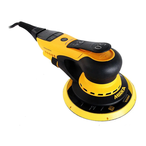
MIRKA CEROS680CV User manual

1
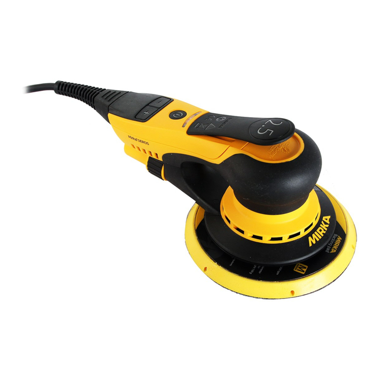
Lijadora roto-orbital eléctrica compacta
Ponceuse orbitale électrique spéciale compacte
MIRKA®CEROS
150 mm (6 in.) • 125 mm (5 in.) • 77mm (3 in.)

2
3
U.S. WARRANTY
See Mirka 2+1 Warranty Booklet for details.
The warranty does not include:
• Normal wear and tear.
• Overloading or improper use i.e.
– Dropping the tool in water
– Damage caused by misuse
– Damage caused by anything other than defects in material and workmanship
– Dropping or other excessive impact
Normal maintenance and service that can be carried out by the operator:
• Changing of the backing pad
• Changing of the exhaust tting
• Changing of the shroud
Note: All other service operations must be carried out by an authorized Mirka service center.
CONFORMS TO UL STD
60745-1, 60745-2-4
CERTIFIED TO CAN/CSA STD
C22.2 No. 60745-1, C22.2 No. 60745-2-4
Intertek
4006707
C US
CM
Input Voltage
110 VAC
Important
Read these instructions
carefully before installing,
operating, servicing or
repairing this tool. Keep
these instructions in a safe
accessible location.
Operator Instructions
Includes – Warranty, Please Read and Comply, Proper
Use of Tool, Work Stations, Putting the Tool Into
Service, Operating Instructions, Product Conguration/
Specications Tables, Parts Page, Parts List, Sander Spare
Parts Kits, Trouble Shooting Guide, Service Instructions
Required Personal Safety Equipment
Safety Glasses Breathing Masks
Safety Gloves Ear Protection
Manufacturer/Supplier
KWH Mirka Ltd
66850 Jeppo, Finland
Tel. +358 20 760 2111
Fax +358 20 760 2290
Declaration of conformity
KWH Mirka Ltd
66850 Jeppo, Finland
declare on our sole responsibility that the product
150 mm (6 in.), 125 mm (5 in.) & 77 mm (3 in.) 10,000 RPM Electrical Random Orbital Sander
(See “Product Conguration/Specications” Table for particular Model) to which this declaration relates
is in conformity with the following standard(s) or other normative document(s) EN ISO
EN 60 745, EN 55 014, EN 61 000 in accordance with the regulations 2006/42/EC , 2004/108/EC.
CompanyPlace and Date of issue
Jeppo 22.8.2013
Ralf Karlström, President and CEO

2
3
FIGURE 1. Sander
FIGURE 2. DC Power transformer unit
On/Off Switch
AC socket
AC Power Cord
LED
DC socket

4
5
General Power Tool Safety Warnings
WARNING Read all safety warnings and all instructions. Failure to follow the warnings and
instructions may result in electric shock, re and/or serious injury.
Save all warnings and instructions for future reference.
The term “power tool” in the warnings refers to any power supplied (corded) power tool or battery-
operated (cordless) power tool.
1) Work area safety
a) Keep work area clean and well lit. Cluttered or dark areas invite accidents.
b) Do not operate power tools in explosive atmospheres, such as in the presence of ammable
liquids, gases or dust. Power tools create sparks which may ignite the dust or fumes.
c) Keep children and bystanders away while operating a power tool. Distractions can cause
you to lose control.
2) Electrical safety
a) Power tool plugs must match the outlet. Never modify the plug in any way. Do not use
any adapter plugs with grounded (earthed) power tools. Unmodied plugs and matching
outlets will reduce risk of electric shock.
b) Avoid body contact with earthed or grounded surfaces, such as pipes, radiators, ranges and
refrigerators. There is an increased risk of electric shock if your body is earthed or grounded.
c) Do not expose power tools to rain or wet conditions. Water entering a power tool will in-
crease the risk of electric shock.
d) Do not abuse the cord. Never use the cord for carrying, pulling or unplugging the power
tool. Keep cord away from heat, oil, sharp edges and moving parts. Damaged or entangled
cords increase the risk of electric shock.
e) When operating a power tool outdoors, use an extension cord suitable for outdoor use.
Use of a cord suitable for outdoor use reduces the risk of electric shock.
f) If operating a power tool in a damp location is unavoidable, use a ground fault circuit
interrupter (GFCI) protected supply. Use of a GFCI reduces the risk of electric shock.
3) Personal safety
a) Stay alert, watch what you are doing and use common sense when operating a power tool. Do
not use a power tool while you are tired or under the inuence of drugs, alcohol or medication.
A moment of inattention while operating power tools may result in serious personal injury.
b) Use personal protective equipment. Always wear eye protection. Protective equipment
such as dust mask, non-skid safety shoes, hard hat, or hearing protection used for appropriate
conditions will reduce personal injuries.
c) Prevent unintentional starting. Ensure the switch is in the o-position before connect-
ing to power source and/or battery pack, picking up or carrying the tool. Carrying power
tools with your nger on the switch or energising power tools that have the switch on invites
accidents.
d) Remove any adjusting key or wrench before turning the power tool on. A wrench or a keyleft
attached to a rotating part of the power tool may result in personal injury.
e) Do not overreach. Keep proper footing and balance at all times. This enables better control
of the power tool in unexpected situations.
f) Dress properly. Do not wear loose clothing or jewellery. Keep your hair, clothing and
gloves away from moving parts. Loose clothes, jewellery or long hair can be caught in mov-
ing parts.
g) If devices are provided for the connection of dust extraction and collection facilities, en-
sure these are connected and properly used. Use of dust collection can reduce dust related
hazards.
4
5
4) Power tool use and care
a) Do not force the power tool. Use the correct power tool for your application. The correct
power tool will do the job better and safer at the rate for which it was designed.
b) Do not use the power tool if the switch does not turn it on and o. Any power tool that can-
not be controlled with the switch is dangerous and must be repaired.
c) Disconnect the plug from the power source before making any adjustments, changing ac-
cessories, or storing power tools. Such preventive safety measures reduce the risk of starting
the power tool accidentally.
d) Store idle power tools out of the reach of children and do not allow persons unfamiliar
with the power tool or these instructions to operate the power tool. Power tools are danger-
ous in the hands of untrained users.
e) Maintain power tools. Check for misalignment or binding of moving parts, breakage of
parts and any other condition that may aect the power tool’s operation. If damaged,
have the power tool repaired before use. Many accidents are caused by poorly maintained
power tools.
f) Use the power tool in accordance with these instructions, taking into account the working
conditions and the work to be performed. Use of the power tool for operations dierent from
those intended could result in a hazardous situation.
5) Service
a) Have your power tool serviced by an authorized Mirka service center using only identical
replacement parts. This will ensure that the safety of the power tool is maintained.
Additional Safety Warnings
a) Always ensure that the material to be sanded is rmly xed to prevent its movement.
b) Dust can be highly combustible. Vacuum dust collection bag should be cleaned or re-
placed daily. Cleaning or replacing of bag also assures optimum performance.
c) Keep hands clear of the spinning pad during use.
d) Do not allow the tool to free speed without taking precautions to protect any persons or
objects from the loss of the abrasive or pad.

6
7
Proper Use of Tool
This sander is designed for sanding a variety of materials e.g. wood, composites, plastics, etc. using
abrasive discs designed for this purpose. Do not use this sander for any other purpose than that
specied without consulting the manufacturer or the manufacturer’s authorized supplier. Do not
press on the shroud when sanding. Pressing on the shroud will reduce its lifespan. Do not use back-
ing pads that have a working speed less than 10,000 RPM free speed. The cooling air vents on the
housing must always be free of blockages to ensure air circulation. Any maintenance or repair work
requiring the motor housing to be opened may only be carried out by an authorized service center.
For optimum results, use sander in conjunction with a dust collection system.
Work Stations
The tool is intended to be operated as a hand held tool. It is always recommended that the tool
should be used when standing on a solid oor. It can be in any position but before any such use, the
operator must be in a secure position having a rm grip and footing and be aware that the sander
can develop a torque reaction.
Disposal Information
Danger!
Disposal information for the old appliance! Render redundant power tools unusable by removing
the power cord. Only for EU countries. Do not dispose of electric tools together with household
waste material! In observance of European Directive 2002/95/CE, 2002/96/EC + 2003/108/CE on
waste electrical and electronic equipment and its implementation in accordance with national law,
electric tools that have reached the end of their life must be collected separately and returned to
an environmentally compatible recycling facility.

6
7
Getting Started
1. Make sure tool is turned o and unplugged. Select a suitable abrasive disc and attach it to the tool,
ensuring that the disc is centered on the backing pad.
2. Connect the cord from the tool to the DC power transformer. Cord will click when locked in place.
Refer to Figure 1–2. Ensure power switch is in the o position.
3. Connect the AC power cord to the DC transformer socket, and plug into grounded wall outlet.
4. Switch on the DC transformer with the On/O switch Figure 2. The power supply LED will cycle
from red to green, indicating that power is available to the tool.
5. Keep hands free of throttle lever. Switch on the sander by pressing the Power Button shown in
Figure 1. The sander LED will turn green, indicating the tool is ready for use.
6. The sander can now be started by pressing the throttle lever.
7. The maximum speed can be adjusted between 4,000 and 10,000 RPM by pressing the RPM+ or RPM–
buttons shown in Figure 1. Each press adds or removes 1,000 RPM until it reaches the limits.
8. The throttle lever can operate in two modes. To change lever modes, press and hold the + and –
buttons for several seconds. In mode 1, it acts as an on/o switch. When the lever is depressed, the
tool will operate at the maximum adjusted speed. In mode 2, the throttle lever acts as a variable
speed switch. As the lever is depressed, the tool will operate between 4,000 rpm and the maxi-
mum adjusted speed.
9. The tool speed can also be adjusted when running. Press the + button to increase speed in 1,000
rpm increments up to 10,000 rpm.
10. For vaccum operation, a 1–1/4" vacuum hose can be threaded into the tool tting.
11. When sanding always place the tool on the work surface then start the tool. Always remove the
tool from the work surface before stopping. This will prevent gouging of the work surface due to
excess speed of the abrasive.
12. When done sanding, or before changing discs, turn o the tool by pressing the power button on
the handle. Switch o the DC transformer, and remove the AC power cord. The power supply LED
will slowly fade. Finally, unplug the power cord between the tool and the DC transformer. ALWAYS
TURN OFF TOOL BEFORE CHANGING ABRASIVE DISCS.

8
9
1
2
3
4
5
6
7
8
9
10
12
13
14
15
11
16
17
18
19
20
21
22
24
23
25
26
27
A
Parts Schematic

8
9
ITEM DESCRIPTION QTY. Part Number
n/s DC Power Supply (Transformer) 1 MIN6522511
n/s Power cable US 110V 1 MIN5617511
1Motor assembly 150 mm / 5 mm
Motor assembly 150 mm / 8 mm
Motor assembly 125 mm / 5 mm
Motor assembly 77 mm / 2.5 mm
1
1
1
1
MIN6510111
MIN6810111
MIN5510111
MIN3210111
2Fan 150 mm / 5 mm
Fan 150 mm / 8 mm
Fan 125 mm / 5 mm
Fan 77 mm / 2.5 mm
1
1
1
1
MIN6510211
MIN6810211
MIN5510211
MIN3210211
3 Double row bearing (150 & 125 mm)
Bearing (77 mm)
1
1
8993019711 (Bearing Kit)
8993019611 (Bearing Kit)
4Spacer 1 8993019711, 8993019611 (Bearing Kit)
5Washer 1 8993019711, 8993019611 (Bearing Kit)
6Retaining ring 1 8993019711, 8993019611 (Bearing Kit)
7 Spindle (150 & 125 mm)
Spindle (77 mm)
1
1
8993011611
8993015011
8 24 mm Pad Wrench (150 & 125 mm)
17 mm Pad Wrench (77 mm)
1
1
8995604121
8993008012
9 Backing Pad (150 mm)
Backing Pad (125 mm)
Backing Pad (77 mm)
1
1
1
916GV15
915GV20
913GV
10 Lever Kit (includes Pin #11) 5 mm orbit
Lever Kit (includes Pin #11) 8 mm orbit
Lever Kit (includes Pin #11) 2.5 mm orbit
1
1
1
MIN6521011 (Lever Kit)
MIN6821011 (Lever Kit)
MIN6221011 (Lever Kit)
11 Pin 1Included with Lever Kit #10
12 Grip 1 MIN6511211
13 Start button 1 MIN6521311 (Start Button Kit)
14 Start button spring 1 MIN6521311 (Start Button Kit)
15 Cover plate 1 MIN6511511
16 PCB screw 4 MIN6522311 (Screw Kit)
17 Speed controller 1 MIN6511711
18 Housing 1 MIN6511811
19 Shroud 150 mm
Shroud 125 mm
Shroud 77 mm
1
1
1
MIN6511911
MIN6515911
MIN3211911
20 Membrane keyboard 1 MIN6512011
21 Cable support 1inc. w / MIN6522211
22 DC cable 4m 1 MIN6522211
23 Housing screw 6 MIN6522311 (Screw Kit)
24 DC connector 1 MIN6512411
25 28 mm swivel exhaust assembly 1 MIN6519011 (Assembly)
26 Washer 1inc. w / MIN6519011
27 Exhaust pipe screw 1inc. w / MIN6519011
n/s Systainer 1 MIN6530011
n/s Fuse for DC Power Supply 1 MIN6512511-2
(n/s = not shown)
Parts List

10
11
Symptom Possible Cause Solution
No light from power supply LED
when switched on.
Power cord not properly attached
to power supply unit or to the AC
socket.
Re-connect cords.
Broken fuse. Please replace the fuse. One spare
fuse is included inside the fuse
holder.
The LED on both power supply
and sander is changing to red
when sanding.
Too heavy long term load. Use lighter load. Switch o the
power. Wait 5 seconds. Switch
on again.
The sander LED is red and
the sander is slowing down
to 4,000 RPM when sanding.
Temperature too high in the sander.
Too heavy long term load.
Reduce load on the sander for some
time and the sander will speed up
again.
The sander LED is red and RPM
is slightly reduced.
Too heavy short term load Use lighter load and the LED will
automatically change to green
CEROS680CV CEROS650CV CEROS550CV CEROS325CV
Power (Peak/Nominal) 400 W / 350 W 400 W / 350 W 400 W / 350 W 400 W / 350 W
Input Voltage 90–240 VAC 90–240 VAC 90–240 VAC 90–240 VAC
DC voltage to sander 22 VDC 22 VDC 22 VDC 22 VDC
Speed 4,000–10,000 rpm 4,000–10,000 rpm 4,000–10,000 rpm 4,000–10,000 rpm
Orbit 8.0 mm 5.0 mm 5.0 mm 2.5 mm
Size of backing pad Ø 150 mm Ø 150 mm Ø 125 mm Ø 77 mm
Weight 940 g 920 g 870 g 700 g
Degree of protection (power) IIII
Degree of protection (sander)
CEROS680CV CEROS650CV CEROS550CV CEROS325CV
Sound pressure level 67.8 dB(A) 67.8 dB(A) 67.8 dB(A) 66.0 dB(A)
Sound power level 78.8 dB(A) 78.8 dB(A) 78.8 dB(A) 77.0 dB(A)
Sound measurement uncertainty K 0.8 dB 0.8 dB 0.8 dB 0.8 dB
Vibration emission value ah3.75 m/s22.82 m/s22.7 m/s25.2 m/s2
Vibration emission uncertainty K 1.0 m/s21.0 m/s21.0 m/s21.0 m/s2
Technical Data
Noise and Vibration Information
Measured values are determined according to EN 60745.
Troubleshooting Guide

10
11
Notes

12
13
CONFORMS TO UL STD
60745-1, 60745-2-4
CERTIFIED TO CAN/CSA STD
C22.2 No. 60745-1, C22.2 No. 60745-2-4
Intertek
4006707
C US
CM
Voltaje de entrada
110 VCA
Importante
Lea estas instrucciones con
atención antes de instalar,
operar, dar mantenimiento
o reparar esta herramienta.
Mantenga estas instrucciones
en un lugar accesible.
Instrucciones de operación
Incluyen: garantía, leer y cumplir, uso adecuado de
la herramienta, estaciones de trabajo, cómo poner la
herramienta en servicio, instrucciones de operación,
tablas de conguración y especicaciones del producto,
página de partes, lista de partes, juegos de partes de
repuesto de la lijadora, guía de solución de problemas
e instrucciones de mantenimiento.
Equipo de seguridad personal requerido
Gafas de seguridad Guantes de seguridad
Máscara para respirar Protección para los oídos
Fabricante y proveedor
KWH Mirka Ltd
66850 Jeppo, Finlandia
Tel. +358 20 760 2111
Fax +358 20 760 2290
Declaración de conformidad
KWH Mirka, Ltd
66850 Jeppo, Finlandia
declara bajo nuestra exclusiva responsabilidad que el producto
“lijadora roto-orbital eléctrica de 150 mm (6"), 125 mm (5") y 77 mm (3"), 10.000 rpm”
(ver la tabla “Conguración y especicaciones del producto” para el modelo en particular
con el cual se relaciona esta declaración), está en conformidad con las siguientes normas u otros
documentos normativos : EN ISO EN 60 745, EN 55 014 y EN 61 000, de acuerdo con las regulaciones
2006/42/EC, 2004/108/EC así como NOM-ETL (NOM-003-SCFI-2000).
EmpresaLugar y fecha de publicación
Jeppo 22.8.2013
Ralf Karlström, Director Ejecutivo
SE AJUSTA AL ESTÁNDAR DE LA UL
60745-1, 60745-2-4
CERTIFICADO AL ESTÁNDAR DE CAN/CSA
C22.2 NO. 60745-1, C22.2 NO. 60745-2-4
GARANTÍA EN LOS ESTADOS UNIDOS
Consulte el folleto de garantía 2+1 Mirka para más detalles.
La garantía no incluye:
• Desgaste y ruptura normal.
• Sobrecarga o uso incorrecto como:
– Dejar caer la herramienta en el agua
– Daño causado por mal uso
– Daño debido a cualquier otra causa que no sean defectos en el material o mano de obra
– Dejarla caer u otros impactos fuertes
Mantenimiento y servicio normales que puede realizar el operador:
• Cambiar la almohadilla de apoyo
• Cambiar el conector de la salida
• Cambiar la protección
Nota: Todas las demás actividades de servicio deben realizarse en un centro de servicio autorizado Mirka.
Spanish

12
13
Figura 1. Lijadora
Figura 2. Alimentación eléctrica de CD (transformador)
Interruptor basculante
enchufe CA
cable eléctrico
LED
tomacorriente CD
enchufe CDplato soporte
conexión de la
manguera de vacío
palanca
RPM –
RPM +
encendido-apagado
LED
Spanish

14
15
Advertencias generales de seguridad de las herramientas de
potencia
ADVERTENCIA. Lea todas las advertencias de seguridad e instrucciones. Si no obedece las
advertencias e instrucciones, podría causar descargas eléctricas, incendio o lesiones serias.
Guarde todas las advertencias e instrucciones para referencia posterior.
El término “herramienta de potencia” en las advertencias se reere a cualquier herramienta de poten-
cia a la que se le suministra energía (con cordón eléctrico) o herramienta de potencia operada con
baterías (inalámbrica).
1) Seguridad en el área de trabajo
a) Mantenga el área limpia y bien iluminada. Las áreas abarrotadas u oscuras son propensas a
accidentes.
b) No trabaje con herramientas de potencia en atmósferas explosivas, por ejemplo en pre-
sencia de líquidos, gases o polvos inamables. Las herramientas de potencia generan chis-
pas que pueden incendiar el polvo o los vapores.
c) Mantenga a los niños o personas que estén cerca alejados mientras trabaja con esta herra-
mienta. Las distracciones pueden hacer que pierda el control.
2) Seguridad eléctrica
a) El enchufe de la herramienta eléctrica debe corresponder a la toma de corriente. Nunca modi-
que el enchufe en ninguna forma. No use enchufes adaptadores con las herramientas de
potencia conectadas a tierra. Los enchufes sin modicar y las tomas de corriente correspon-
dientes reducen el riesgo de causar descargas eléctricas.
b) Evite el contacto del cuerpo con supercies conectadas a tierra tales como tubos, radiadores,
campanas de cocina y refrigeradores. Si el cuerpo llegara a hacer tierra, existe un mayor riesgo
de sufrir una descarga eléctrica.
c) No exponga las herramientas de potencia a la lluvia o condiciones de humedad. Si el agua in-
gresa en una herramienta de potencia, aumentará el riesgo de causar una descarga eléctrica.
d) No haga mal uso del cordón eléctrico. Nunca use el cordón eléctrico para cargar, jalar o des-
conectar la herramienta de potencia. Mantenga el cordón eléctrico alejado del calor, bor-
des cortantes o partes en movimiento. Los cordones eléctricos dañados o enredados pueden
aumentar el riesgo de descarga eléctrica.
e) Cuando trabaje con una herramienta de potencia al aire libre, use un cable de extensión
adecuado para uso externo. El uso de un cable adecuado para el exterior reduce el riesgo de
causar descarga eléctrica.
f) Si es inevitable trabajar con una herramienta de potencia en un lugar húmedo, use una corrien-
te con interruptor de circuito de falla a tierra (ICFT). El uso de un ICFT reduce el riesgo de
descarga eléctrica.
3) Personal safety
a) Manténgase alerta, observe lo que está haciendo y use el sentido común cuando trabaje con una
herramienta de potencia. No use herramientas de potencia cuando esté cansado o bajo los
efectos de drogas, alcohol o medicamentos. Un momento de distracción al trabajar con una
herramienta de potencia puede resultar en lesiones serias.
b) Use equipo de protección personal. Use siempre protección para los ojos. El uso de equipo
de protección tal como calzado de seguridad antiderrapante, casco de seguridad o protección
para los oídos reducirá el riesgo de lesiones.
c) Prevenga el arranque involuntario. Verique que el interruptor esté en posición apagada
antes de conectar la herramienta a una fuente eléctrica o baterías, o antes de levantarla y
moverla. Mover herramientas de potencia con el dedo en el interruptor o habilitar la corriente
en herramientas con el interruptor encendido predispone a causar accidentes.
d) Retire cualquier llave o instrumento de ajuste antes de encender la herramienta. Una llave que se
deje ja en una pieza rotativa de la herramienta de potencia pueda causar lesiones.

14
15
e) No se estire. Mantenga la postura y equilibrio en todo momento. Esto permite controlar me-
jor la herramienta en situaciones imprevistas.
f) Use ropa adecuada. No use ropa oja ni joyas. Mantenga su pelo, ropa y guantes alejados
de las partes móviles. La ropa oja, la joyería o el pelo largo pueden quedar atrapados en las
partes en movimiento.
g) Si se proporcionan dispositivos para conectar equipos de extracción y aspiración, asegúrese de
que estén conectados y que se usen correctamente. El uso de aspiración del polvo puede redu-
cir los riesgos relacionados con éste.
4) Uso y cuidado de la herramienta de potencia
a) No fuerce la herramienta de potencia. Use la herramienta de potencia adecuada para su acti-
vidad en particular. La herramienta de potencia correcta hará un trabajo mejor y más seguro a
la capacidad para la que fue diseñada.
b) No use la herramienta de potencia si el interruptor no se enciende y apaga. Toda herramienta de
potencia que no pueda controlarse con el interruptor es peligrosa y debe repararse.
c) Desconecte el enchufe de la fuente de energía antes de hacer ajustes, cambiar accesorios
o de guardar la herramienta de potencia. Estas medidas preventivas de seguridad reducen el
riesgo es arrancar la herramienta en forma accidental.
d) Guarde las herramientas de potencia que no use fuera del alcance de los niños y no permita que
personas que no están familiarizadas con la herramienta o con estas instrucciones trabajen con
la herramienta. Las herramientas de potencia son peligrosas en manos de usuarios sin capaci-
tación en ellas.
e) Dé mantenimiento a las herramientas de potencia. Revise si existe falta de alineación o e-
xión en las partes móviles, rompimiento de partes o cualquier otra condición que pudiera
afectar el funcionamiento de la herramienta. Si está dañada, mande a reparar la herra-
mienta antes de volver a usarla. Muchos accidentes se deben a herramientas con manteni-
miento deciente.
f) Use la herramienta de potencia de acuerdo con estas instrucciones, y tome en cuenta las condi-
ciones de trabajo y el trabajo que va a realizar. El uso de la herramienta de potencia para trabajos
que no sean los previstos podría causar situaciones peligrosas.
5) Servicio
a) Mande su herramienta de potencia a servicio a un centro de servicio autorizado Mirka, y
use solamente partes de repuesto originales. Esto garantizará que se mantenga la seguridad
de la herramienta.
Otras advertencias de seguridad
a) Asegure siempre que el material que va a lijar esté bien jo para prevenir que se mueva.
b) El polvo puede ser altamente combustible. La bolsa de recolección de polvo por aspiración debe
limpiarse o reemplazarse diariamente. La limpieza o reemplazo de la bolsa también garantiza el
funcionamiento óptimo.
c) Mantenga las manos alejadas de la almohadilla giratoria durante el uso.
d) No permita que la herramienta gire libremente sin tomar precauciones para proteger a las per-
sonas u objetos del disco abrasivo o almohadilla.

16
17
Uso adecuado de la herramienta
Esta lijadora está diseñada para usarse en varios materiales como madera, materiales compuestos,
plásticos y otros, mediante el uso de discos abrasivos fabricados para este propósito. No use esta
lijadora para ningún otro propósito que el especicado sin antes consultar al fabricante o al pro-
veedor autorizado del fabricante. No presione la protección durante el lijado. La presión sobre la
protección reducirá su vida útil. No use almohadillas de apoyo que tengan una velocidad de ope-
ración menor de 10.000 rpm. Las salidas de aire de enfriamiento en la carcasa deben estar siempre
libres de obstrucciones y limpias para asegurar la circulación. Todo trabajo de mantenimiento o
reparación que requiera que se abra la carcasa del motor solo debe hacerse a través de un centro
de servicio autorizado.
Para los resultados óptimos, utilice la lijadora conjuntamente con un sistema de eliminación del
polvo.
Estaciones de trabajo
Esta herramienta está diseñada para funcionar como herramienta manual. Se recomienda siempre
que la herramienta se use de pie sobre un piso rme. Puede colocarse en cualquier posición, pero
antes de usarla así, el operador debe estar en una postura segura que tenga un agarre y apoyo
rmes, y tener presente que la herramienta puede generar una reacción de tensión.
Información sobre el desecho
¡Peligro!
¡Información de desecho de herramientas usadas! Convierta las herramientas usadas en inútiles
al quitarles el cordón eléctrico. Solo para países de la Unión Europea. No deseche las herramien-
tas eléctricas junto con material de desecho doméstico. En cumplimiento de la Directiva Europea
2002/95/CE, 2002/96/EC y 2003/108/CE sobre equipos eléctricos y electrónicos de desecho y su
implementación en conformidad con las leyes federales, las herramientas eléctricas que hayan lle-
gado al nal de su vida útil deben recolectarse aparte y enviarse a una planta de reciclaje compa-
tible con el medio ambiente.

16
17
Cómo empezar
1. Asegúrese de que la herramienta esté apagada y desenchufada. Seleccione un disco abrasivo
adecuado y colóquelo en la herramienta, y verique que el disco quede centrado sobre la almo-
hadilla de apoyo.
2. Conecte el cordón eléctrico de la herramienta en el transformador de energía de corriente directa
(CD). El cordón hará clic cuando se trabe en su lugar. Vea la Figura 1–2. Verique que el interruptor
esté apagado.
3. Conecte el cordón de corriente alterna (CA) en el conector del transformador de corriente directa
y enchúfelo en una toma de corriente en la pared.
4. Encienda el transformador de corriente directa con el interruptor de encendido que se muestra
en la Figura 2. La luz LED de corriente cambiará de roja a verde para indicar que hay corriente
habilitada hacia la herramienta.
5. Mantenga las manos alejadas de la palanca del acelerador. Encienda la lijadora al presionar el bo-
tón de encendido que se muestra en la Figura 1. La luz LED de la lijadora se pondrá verde para
indicar que la herramienta ya puede usarse.
6. La lijadora puede arrancarse al presionar la palanca del acelerador.
7. La velocidad máxima puede ajustarse entre 4.000 y 10.000 rpm al presionar los botones “RPM+”
o “RPM–” que se muestran en la Figura 1. Cada vez que uno de estos se presiona, se aumenta o
reduce 1.000 rpm hasta que llega al límite.
8. La palanca del acelerador funciona en dos modos. Para cambiar los modos de la palanca, presione
y mantenga así los botones “+” y “–” durante varios segundos. En el modo 1, actúa como interrup-
tor de encendido. Cuando se presiona la palanca, la herramienta funciona a la máxima velocidad
ajustada. En el modo 2, la palanca de velocidad funciona como interruptor de velocidad variable.
A medida que se presiona la palanca, la herramienta funcionará entre 4.000 rpm y la máxima ve-
locidad ajustada.
9. La velocidad de la herramienta también puede ajustarse cuando está trabajando. Presione el bo-
tón “+” para aumentar la velocidad en incrementos de 1.000 rpm hasta 10.000 rpm.
10. Para funcionamiento con aspiración, se puede conectar una manguera de aspiración de 1 1/4" en
la conexión de la herramienta.
11. Cuando lije, siempre coloque la herramienta sobre la supercie de trabajo y luego enciéndala.
Retire la herramienta de la supercie de trabajo antes de apagarla. Esto evitará que se dañe la
supercie de trabajo debido a la velocidad excesiva del disco.
12. Cuando termine de lijar, o antes de cambiar discos, apague la herramienta al presionar el botón de
encendido en la manija. Apague el transformador de corriente directa y retire el cordón eléctrico
de corriente alterna. La luz LED de alimentación se apagará lentamente. Por último, desenchufe
el cordón eléctrico que está entre la herramienta y el transformador de corriente directa. APAGUE
SIEMPRE LA HERRAMIENTA ANTES DE CAMBIAR LOS DISCOS ABRASIVOS.

18
19
1
2
3
4
5
6
7
8
9
10
12
13
14
15
11
16
17
18
19
20
21
22
24
23
25
26
27
A
Diagrama de partes

18
19
Lista de partes
N.° DESCRIPCIÓN CANT. Número de parte
n/m Alimentación eléctrica de CD (transformador) 1 MIN6522511
n/m Cordón eléctrico US 110 V 1 MIN5617511
1Conjunto de motor 150 mm / 5 mm
Conjunto de motor 150 mm / 8 mm
Conjunto de motor 125 mm / 5 mm
Conjunto de motor 77 mm / 2,5 mm
1
1
1
1
MIN6510111
MIN6810111
MIN5510111
MIN3210111
2Ventilador 150 mm / 5 mm
Ventilador 150 mm / 8 mm
Ventilador 125 mm / 5 mm
Ventilador 77 mm / 2.5 mm
1
1
1
1
MIN6510211
MIN6810211
MIN5510211
MIN3210211
3Cojinete de doble la (150 & 125 mm)
Cojinete (77 mm)
1
1
8993019711 (juego de cojinete)
8993019611 (juego de cojinete)
4Espaciador 18993019711, 8993019611 (juego de cojinete)
5Roldana 18993019711, 8993019611 (juego de cojinete)
6Anillo de seguridad 18993019711, 8993019611 (juego de cojinete)
7 Husillo (150 & 125 mm)
Husillo (77 mm)
1
1
8993011611
8993015011
8Llave para cojinete de 24 mm (150 & 125 mm)
Llave para cojinete de 17 mm (77 mm)
1
1
8995604121
8993008012
9 Plato Soporte (150 mm)
Plato Soporte (125 mm)
Plato Soporte (77 mm)
1
1
1
916GV15
915GV20
913GV
10 Palanca (5 mm)
Palanca (8 mm)
Palanca (2,5 mm)
1
1
1
MIN6521011 (juego de palanca)
MIN6821011 (juego de palanca)
MIN6221011 (juego de palanca)
11 Pasador 1 incluido con Juego de Palanca
12 Agarradera 1 MIN6511211
13 Botón de encendido 1MIN6521311 (juego del botón de encendido)
14 Resorte de botón de encendido 1MIN6521311 (juego del botón de encendido)
15 Placa de cubierta 1 MIN6511511
16 Tornillo PCB 4MIN6522311 (juego de tornillos)
17 Controlador de velocidad 1 MIN6511711
18 Carcasa 1 MIN6511811
19 Protección 150 mm
Protección 125 mm
Protección 77 mm
1
1
1
MIN6511911
MIN6515911
MIN3211911
20 Teclado de membrana 1 MIN6512011
21 Soporte de cable 1inc. c / MIN6522211
22 Cable de CD de 4 m 1 MIN6522211
23 Tornillo de carcasa 6MIN6522311 (juego de tornillos)
24 Conector de CD 1 MIN6512411
25 Conjunto de escape giratorio de 28 mm 1MIN6519011 (conjunto)
26 Roldana 1inc. c / MIN6519011
27 Tornillo de tubo de escape 1inc. c / MIN6519011
n/m Systainer 1 MIN6530011
n/m Fusible para el transformador 1 MIN6512511-2
(n/m = no mostrado)

20
21
Síntoma Causa posible Solución
No se ilumina la LED de corriente
al encenderla.
El cordón eléctrico no está bien
conectado en la unidad de alimen-
tación de corriente o en el conector
de corriente alterna.
Reconecte los cordones.
Fusible quemado. Reemplace el fusible. Se incluye un
fusible de repuesto dentro del
sujetador de fusible.
La LED en la alimentación de
corriente y en la lijadora cambia
a roja al lijar.
Carga duradera demasiado alta. Use una carga más ligera. Apague
la corriente. Espere 5 segundos y
vuelva a encender.
La LED de la lijadora está roja
y la lijadora está reduciendo la
velocidad a 4.000 rpm al lijar.
La temperatura de la lijadora es muy
alta. Carga duradera demasiado alta.
Reduzca la carga en la lijadora
durante algún tiempo y la lijadora
aumentará la velocidad nuevamente.
La LED de la lijadora está roja
y las rpm están ligeramente
reducidas.
Carga breve demasiado alta. Use una carga más ligera y la LED
cambiará automáticamente a verde.
CEROS680CV CEROS650CV CEROS550CV CEROS325CV
Potencia (pico/nominal) 400 W / 350 W 400 W / 350 W 400 W / 350 W 400 W / 350 W
Voltaje de entrada 90–240 VCA 90–240 VCA 90–240 VCA 90–240 VCA
Voltaje de CD hacia lijadora 22 VCD 22 VCD 22 VCD 22 VCD
Velocidad 4.000–10.000 rpm 4.000–10.000 rpm 4.000–10.000 rpm 4.000–10.000 rpm
Órbita 8,0 mm 5,0 mm 5,0 mm 2,5 mm
Tamaño del Plato Soporte Ø 150 mm Ø 150 mm Ø 125 mm Ø 77 mm
Peso 940 g 920 g 870 g 700 g
Grado de protección de la corriente IIII
Grado de protección de la lijadora
CEROS680CV CEROS650CV CEROS550CV CEROS325CV
Nivel de presión del sonido 67,8 dB(A) 67,8 dB(A) 67,8 dB(A) 66.0 dB(A)
Nivel de potencia del sonido 78,8 dB(A) 78,8 dB(A) 78,8 dB(A) 77.0 dB(A)
Error de la medición del sonido K 0,8 dB 0,8 dB 0,8 dB 0,8 dB
Valor de emisión de vibración ah3,75 m/s22,82 m/s22,7 m/s25,2 m/s2
Error de emisión de vibración K 1,0 m/s21,0 m/s21,0 m/s21,0 m/s2
Datos técnicos
Información de ruido y vibración
Los valores medidos están determinados de acuerdo con EN 60745.
Guía de solución de problemas
This manual suits for next models
3
Table of contents
Languages:
Other MIRKA Sander manuals

MIRKA
MIRKA DEROS MID65020US User manual

MIRKA
MIRKA RPS 300CV User manual

MIRKA
MIRKA PS 1524 User manual

MIRKA
MIRKA CEROS User manual

MIRKA
MIRKA AROS-B 150NV User manual

MIRKA
MIRKA ROS525 User manual

MIRKA
MIRKA Random Orbital Sander User manual

MIRKA
MIRKA AROS-B 150NV User manual

MIRKA
MIRKA MR-34 User manual

MIRKA
MIRKA ROS2-850CV User manual

MIRKA
MIRKA ROS User manual

MIRKA
MIRKA ARP-B 300NV User manual

MIRKA
MIRKA CEROS625CV User manual

MIRKA
MIRKA PROS User manual

MIRKA
MIRKA DEOS 343X User manual

MIRKA
MIRKA DEROS 325CV User manual

MIRKA
MIRKA 8 Operating instructions

MIRKA
MIRKA DEOS 383X CV User manual

MIRKA
MIRKA AIROS User manual

MIRKA
MIRKA Mirka ROS series User manual