MIRKA AIROS User manual


2Mirka® AIROS • 77 mm (3"), 125 mm (5") & 150 mm (6") • Electrical manual
Warranty
Mirka warrants that your components are free from manufacturing and material defects.
Mirka components have a 1-year warranty starting from the date of purchase. Only manufacturing and material
defects are covered by the warranty.
If a problem occurs caused by a manufacturing defect material or by workmanship, Mirka will repair your
component free of charge in accordance with the warranty terms and conditions stated herein. To keep your
component warranty valid the component must be used, maintained and operated in compliance with the
operating instructions.
Terms and conditions
Mirka’s component warranty covers defects in material and workmanship.
Components covered by the warranty:
• motor drive
• sanding unit
• polishing unit
• power supply
• communication gateway
Warranty does not cover:
• any damage caused or resulting from transport, receipt of delivery, installation, commissioning, misuse, neglect
in usage or maintenance, accidents, exposure to extreme unacceptable ambient temperature, acids, water,
unsuitable storage, excessive impact, or operation outside the rated specifications.
• defects caused by spare parts, accessories or components other than Mirka original spare parts or accessories.
• normal wear and tear items such as: backing pad, break seal, exhaust fitting, bearings, rubber mount, signal cable
or power cable.
• components that have been: modified, repaired or repair attempts (by other than Mirka authorized service), partly
or completely disassembled components.
No other than Mirka have the authority to change, extend or add to given warranty terms and conditions.
The manufacturer cannot be hold responsible for consequential damages compensations for downtime, production loss,
injuries or property damages.
A warranty claim must be submitted with as short delay as possible. A warranty claim must be submitted within the
warranty period.

2Mirka® AIROS • 77 mm (3"), 125 mm (5") & 150 mm (6") • Electrical manual Mirka® AIROS • 77 mm (3"), 125 mm (5") & 150 mm (6") • Electrical manual 3
Installation overview
Component spare part codes
Name Mirka code
Power supply 48V MIA6513211
Power supply 24 V MIA6513411
Hilscher NT 50-RS-EN MIA6513311
Hilscher NT 50-RS-EN adapter cable MIA6514011
Motor drive MIA6513112
Shielded cable for tool (10 m) MIA6512311
48 VDC PSU
24 VDC PSU
Motor drive Tool
4-bit digital controlModbus RTU masterProfinet I/O gateway
Profinet I/O controller
Optional Hilschner NT 50-RS-EN Profinet I/O gateway addon module
J2
J1 J5, J6
J3
J4
General
• Connect the 48 VDC power supply to the motor drive (J2 connector).
• Connect the tool to the motor drive (J3 and J7 connector).
Modbus RTU interface
• Use the J1 connector to connect the motor drive to the Modbus RTU bus.
Profinet I/O gateway to Modbus RTU interface
• Connect the 24 VDC power supply to the gateway and connect the DSUB-9 adapter cable between the gateway (
X2 connector) and the motor drive (J1 connector).
Digital control interface
• Use the J6 connector to connect the common GND between the systems.
• Use the J5 connector to select the operation using the four digital input signals.
Relay interface
• The N/O relay pins are available on the J4 connector.

4Mirka® AIROS • 77 mm (3"), 125 mm (5") & 150 mm (6") • Electrical manual
Technical data
Input
Nominal input voltage 48 VDC
Input voltage range 46–50 VDC
Maximum input current 10 A
Rated power 350 W
Speed control
Speed range 4000–10000 rpm
Protection
Overload protection Yes
Overheat protection Yes
Interfaces
Input interfaces Modbus RTU (RS-485), Profinet I/O (gateway module), 4-bit digital
inputs (15–33 VDC)
Output interfaces Single pole, non-latching N/O relay, 250 VAC / 125 VDC, 10 A
Environmental
Ambient temperature 0–40°C
Humidity Maximum 95% RH, non-condensing, non-corrosive, no dripping water
Storage temperature –20 to 80°C
Dimensions
Motor drive 72 x 30 x 200 mm (W x H x D)
Motor drive mounted in DIN-rail holder 95 x 55 x 210 mm (W x H x D)
Safety instructions
Electrical installation must be carried out by a competent
electrician!
Warnings
Make sure that all the AC-DC power supplies are properly earthed and that the motor drive cannot come in
contact with live mains voltage.
An external emergency stop circuit is recommended.
Safety instructions
The motor drive has been designed for fixed installations only.
Do not perform any voltage withstand tests on any part of the motor drive or the tool. Product safety has
been fully tested at the factory.
Ground yourself with an anti-static wristband before touching the motor drive (setting jumpers and similar
actions) to avoid electrostatic voltage discharge damage to the motor drive.

4Mirka® AIROS • 77 mm (3"), 125 mm (5") & 150 mm (6") • Electrical manual Mirka® AIROS • 77 mm (3"), 125 mm (5") & 150 mm (6") • Electrical manual 5
Before running the tool
Before starting the tool, check that the tool is mounted properly and ensure that the motor drive is
installed properly.
Dimensions specified
in millimeters.
The motor drive PCB comes mounted in a DIN-rail holder that can be attached to a standard 35 x 7.5mm EN50022
DIN-rail, but the motor drive PCB can be removed from this holder and mounted using the mounting holes instead.
If the mounting holes are used, then it is recommended to use 20 mm metal standoffs and 10 mm M3 screws when
mounting the motor drive PCB.
It is recommended to use 10 mm ferrules with plastic sleeve for each wire that is attached to any of the connectors.
The wires can then easily be pushed into the connectors and released with the help of a small flat-head screwdriver
(3.5 mm blade width, 0.6 mm blade thickness).
Connector description
Connector PIN Description
J1 GND GND
J1 A Modbus RTU RS-485 (A)
J1 B Modbus RTU RS-485 (B)
J1 GND GND
Connector PIN Description
J2 GND GND
J2 48V 48 VDC input
Motor drive overview
Motor drive PCB connectors, buttons, jumpers, indicators, mounting holes and dimensions
B
J3
JP13
JP15
J4
D17
D21
NTC+
NO
D26
D2
D18
D3
D19
D20
D23
D24
GND
J6
15V
A
DI4
GND
DI2
JP3
JP4
J5
DI1
D4
JP2
JP1
S2
S1
GND
155
D36
P+
C+
P-
GND
NTC-
72
D22
D25
JP12
GND
J1
D30
D14
J2
C-
PhaseB
COM
DI3
200
48V
15
6
PhaseA
PhaseC
6
ø3,20
D29

6Mirka® AIROS • 77 mm (3"), 125 mm (5") & 150 mm (6") • Electrical manual
Connector PIN Description
J3 P+ P+
J3 C+ C+
J3 C– C–
J3 P– P–
J3 NTC+ NTC+
J3 Phase A Phase A
J3 Phase B Phase B
J3 Phase C Phase C–
J3 GND GND
J3 NTC- NTC–
Connector PIN Description
J4 COM Relay COM
J4 NO Relay NO
Connector PIN Description
J5 DI1 Digital speed control input bit 1
J5 DI2 Digital speed control input bit 2
J5 DI3 Digital speed control input bit 3
J5 DI4 Digital speed control input bit 4
Connector PIN Description
J6 15V 15 VDC output
J6 GND GND
Button description
Button Description
S1 Self-test button
S2 Reset button
Indicator description
Indicator Description
D2 Speed set-point indicator, lit if ≥ 4,000 rpm. Modbus RTU slave address indicator, bit 1.
D3 Speed set-point indicator, lit if ≥ 5,000 rpm. Modbus RTU slave address indicator, bit 2.
D4 Tool status indicator. Lit red when the tool is stopped, lit green when the tool is running.
D14 Motor drive state indicator. Lit green when motor drive is in ON-state. Blinking green when
motor drive is in OFF-state.
D17 Speed set-point indicator, lit if ≥ 6,000 rpm. Modbus RTU slave address indicator, bit 3.
D18 Speed set-point indicator, lit if ≥ 7,000 rpm. Modbus RTU slave address indicator, bit 4.
D19 Speed set-point indicator, lit if ≥ 8,000 rpm. Modbus RTU slave address indicator, bit 5.
D20 Speed set-point indicator, lit if ≥ 9,000 rpm. Modbus RTU slave address indicator, bit 6.
D21 Speed set-point indicator, lit if ≥ 10,000 rpm. Modbus RTU slave address indicator, bit 7.
D22 Modbus RTU slave address indicator, bit 8.
D23 Lit if D2–D3, D17–D22 indicator mode is Modbus RTU slave address.

6Mirka® AIROS • 77 mm (3"), 125 mm (5") & 150 mm (6") • Electrical manual Mirka® AIROS • 77 mm (3"), 125 mm (5") & 150 mm (6") • Electrical manual 7
Tool cable connector pinout
PIN (colour, size) Description
PE (green–yellow,
1.0 mm2)Not in use
1 (brown, 1.00 mm²) Phase A
2 (blue, 1.00 mm²) Phase B
3 (black, 1.00 mm²) Phase C
A (grey, 0.25 mm²) C–
B (pink, 0.25 mm²) C+
C (green, 0.25 mm²)
C (yellow, 0.25 mm²)
P–
NTC–
D (brown, 0.25 mm²) NTC+
E (white, 0.25 mm²) P+
NOTE: NTC– and P– are connected together to the same PIN inside the connector.
Hilscher NT 50-RS-EN adapter cable pinout (female DSUB-9)
PIN (colour) Description
1 (white, WH) GND
4 (brown, BN) Modbus RTU (A, RxD / TxD+)
5 (green, GN) Modbus RTU (B, RxD / TxD–)
SHIELD Shield
Jumper description
Jumpers Default Description
JP1 Not set Reserved for future use.
JP2 Not set If set, a terminating resistor of 270 Ω is connected across
Modbus RTU pins A and B.
JP3 Not set If set, a pull-down resistor of 10 kΩ is connected to Modbus
RTU B-pin.
JP4 Not set If set, a pull-up resistor of 10 kΩ is connected to Modbus RTU
A-pin.
JP12 Not set If set, digital speed control feature is enabled.
JP13 Not set If set, D2–D3, D17–D22 indicators will output the current
Modbus RTU slave address instead of speed set-point.
JP15 Not set Reset to factory settings.
D24 Lit if digital speed control interface is enabled.
D25 Lit if the alarm status flag is set.
D26 Relay status indicator.
D29 Modbus RTU receive indicator.
D30 Modbus RTU transmit indicator.
D36 Possible tool wiring fault.

8Mirka® AIROS • 77 mm (3"), 125 mm (5") & 150 mm (6") • Electrical manual
RS-485 configuration
BAUD R ATE 19200
PARITY EVEN
STOP BITS 1
DATA BITS 8
Coil registers (F1, F5, F15)
Address Data type Name Description
00001–00012 Uint16 Digital outputs Coils 1–11 are reserved for future use.
Coil 12 is the relay located on the motor drive.
Modbus RTU
Modbus RTU over RS-485 is used to communicate with the motor drive. The motor drive is configured as a Modbus
RTU slave device and the default slave address is 86. The slave address can be changed if it conflicts with another
Modbus RTU slave device.
The J1 connector on the motor drive is used for Modbus RTU communication. A shielded twisted pair cable is
recommended and the shield should be earthed only at one point, normally at the master device. The A-pin of the J1
connector is equivalent to RxD / TxD+ and the B-pin is equivalent to RxD / TxD–.

8Mirka® AIROS • 77 mm (3"), 125 mm (5") & 150 mm (6") • Electrical manual Mirka® AIROS • 77 mm (3"), 125 mm (5") & 150 mm (6") • Electrical manual 9
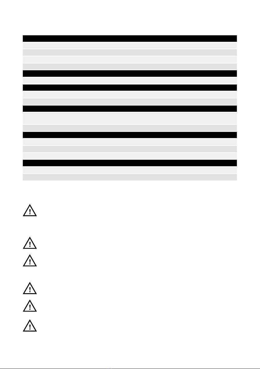
Input registers (F4)
Address Data type Name Description
30001 Uint16 Drop RPM count The number of times the speed has dropped from
set-point by more than 25%.
30002 Uint16 Warm tool count The number of times the tool temperature has
exceeded the “warm” limit, 79°C.
30003 Uint16 Warm motor drive count The number of times the motor drive temperature has
exceeded the “warm” limit, 73°C.
30004 Uint16 Hot tool count The number of times the tool temperature has
exceeded the “hot” limit, 134°C.
30005 Uint16 Hot motor drive count The number of times the motor drive temperature has
exceeded the “hot” limit, 117°C.
30006 Uint16 Stop tool count The number of times the tool temperature has
exceeded the “stop” limit, 142°C.
30007 Uint16 Stop motor drive count The number of times the motor drive temperature has
exceeded the “stop” limit, 123°C.
30008 Uint16 Voltage out of range count The number of times the input voltage has not been
within 44 to 52 VDC.
30009 Uint16 Over-current low count The number of times the current has exceeded 15.1 A.
30010 Uint16 Over-current medium count The number of times the current has exceeded 18.2 A.
30 011 Uint16 Usage count long The number of times the run time has been more than
60 seconds.
30012 Uint16 Usage count medium The number of times the run time has been between
20 and 60 seconds.
30013 Uint16 Usage count short The number of times the run time has been less than
20 seconds.
30014 Uint16 Usage time hours Hours part of usage time.
30015 Uint16 Usage time minutes Minutes part of usage time.
30016 Uint16 Usage time seconds Seconds part of usage time.
30017 Int16 Average current Average current in mA.
30018 Uint16 Average speed Average speed in RPM.
30019 Uint16 Tool temperature Tool temperature in °C.
30020 Uint16 Motor drive temperature Motor drive temperature in °C.
30021–30030 Char[20] Firmware version Firmware version and build date, e.g. “2.0 Jan 18 14:00”.
30031–30040 Char[20] Part version Part version and motor drive serial number, e.g. “AI1.3
123456”.
30041–30046 Char[12] Product serial number Product serial number, e.g. “749474379001”
30047 Uint16 Alarm status flag Alarm status flag can hold one of the following values
at any given time. This flag is automatically cleared
after 5 seconds if the cause of the alarm trigger is no
longer present.
0x0000 = Not triggered
0x0001 = Tool overheated
0x0002 = Motor drive overheated
0x0004 = Over-current
0x0008 = Under-voltage
0x0010 = Over-voltage
0x0020 = Self-test running
0x0040 = RPM drop
0x0080 = High current
0x0100 = Tool change in progress
0x0200 = Possible tool wiring fault
0x0400 = Factory reset mode

10 Mirka® AIROS • 77 mm (3"), 125 mm (5") & 150 mm (6") • Electrical manual
Holding registers (F3, F6, F16)
Address Data type Name Description
40001–40010 Char[20] Device name Max length 19 printable characters,
e.g. “AIMD 749474379001”.
40011 Uint16 Speed set-point Speed set-point, not the actual speed, between
4,000–10,000 RPM.
40012 Uint16 Operation
Motor drive state, can be a combination of the
following:
0x0001 = RUN
0x0002 = STOP
0x0004 = ON
0x0008 = OFF
0x0010 = TOOL CHANGE START
0x0020 = TOOL CHANGE END
NOTE: When writing a new state value, the value can
only be a single state, not a combination of multiple
states, e.g. ON+RUN cannot be written simultaneously.
40013 Uint16 Slave address Defaults to 86 but can be changed if needed.
RS-485 PIN Signal Description
DSUB-9 male
1GND Reference potential, ground of power supply
4 RxD / TxD+ Receive data / Transmit data positive
5 RxD / TxD– Receive data / Transmit data negative
Profinet I/O gateway (Hilscher NT 50-RS-EN)
If the motor drive needs to be connected to a Profinet I/O device the Hilscher NT 50-RS-EN gateway can be used. The
gateway is connected to the motor drive via the DSUB-9 connector on the gateway and the J1 connector on the motor
drive. Below is the pinout for the DSUB-9 (X2 connector) found on the gateway:
A pull-up resistor of 10 kΩ is internally connected in the gateway to“RxD / TxD+”.
A pull-down resistor of 10 kΩ is internally connected in the gateway to “RxD / TxD–”.
Detailed documentation about the gateway and configuration tools can be downloaded from the Hilscher website:
https://www.hilscher.com/products/product-groups/gateways/for-the-control-cabinet-ip20/entry-level-gateways/nt-
50-rs-enmbrpns/
Configuration
The gateway comes pre-configured from Mirka as a Profinet I/O slave device. The“SYCON.net” software from Hilscher
can be used to re-configure the device. The “Ethernet Device Setup”software from Hilscher can be used to change
the network configuration, use the DCP protocol. The IP address usually needs to be re-assigned after a configuration
change.
The default configuration can be downloaded from the Mirka website www.mirka.com
Default network configuration
IP ADDRESS 192.168.2.191
SUBNET MASK 255.255.255.0
DEFAULT GATEWAY 0.0.0.0
DEVICE NAME nt50enpns
1
4
5

10 Mirka® AIROS • 77 mm (3"), 125 mm (5") & 150 mm (6") • Electrical manual Mirka® AIROS • 77 mm (3"), 125 mm (5") & 150 mm (6") • Electrical manual 11
Siemens TIA Portal V14 gateway mapping example
Below is a screenshot from TIA Portal V14 showing how the gateway can be mapped into the system. Use the GSDML
file that is downloadable from the Hilscher website to add support for the Hilscher NT 50-RS-EN gateway into your
system.
Basic operation for Modbus RTU
The motor drive must be in ON-state before the tool can be started. The very first command that should be sent to the
motor drive is the ON-state command. It is not mandatory to send the OFF-state command before removing power
from the motor drive.
When the motor drive is in ON-state the speed set-point value can be written and the state can be set to RUN-state by
sending the RUN-state command. This will cause the tool to run at the set-point speed. To stop the tool, set the motor
drive to STOP-state by sending the STOP-state command.
It is recommended to continuously monitor the average speed, average current, tool temperature, motor drive
temperature and the alarm status flag. This will help to detect if there are any issues present during operation.
Profinet I/O to Modbus RTU signal mapping
Name Modbus
register
Data
length Trigger Profinet
I/O slot
Data
length
SetRelay 00012 1 coil Changed data 1 1 byte out
SetSpeedRegister 40011 1 register Changed data 2 1 word out
SetOperationRegister 40012 1 register Changed data 3 1 word out
DeviceName 40001–40010 10 registers Cyclically 10 sec. 4 10 words in
CommonInputs 30017–30020 4 registers Cyclically 1 sec. 5 4 words in
MiscInputs 30001–30016 16 registers Cyclically 5 sec. 6 16 words in
AlarmStatus 30047 1 register Cyclically 1 sec. 7 1 word in
FirmwareVersion 30021–30030 10 registers Cyclically 10 sec. 8 10 words in
PartVersion 30031–30040 10 registers Cyclically 10 sec. 9 10 words in
SerialNumber 30041–30046 6 registers Cyclically 10 sec. 10 6 words in
GetSpeedRegister 40011 1 register Cyclically 1 sec. 11 1 word in
GetOperationRegister 40012 1 register Cyclically 1 sec. 12 1 word in
ReadCoils 00001–00012 12 coils Cyclically 1 sec. 13 2 bytes

12 Mirka® AIROS • 77 mm (3"), 125 mm (5") & 150 mm (6") • Electrical manual
Example sequence for starting and stopping the tool:
• Write 4 (0x0004) to the“Operation” register, this will set the motor drive to ON-state.
• Write 4000 (0x0FA0) to the “Speed set-point”register, this will set the set-point speed to 4,000 rpm.
• Write 1 (0x0001) to the“Operation” register, this will set the motor drive to RUN-state and the tool will start running.
• Write 2 (0x0002) to the“Operation” register, this will set the motor drive to STOP-state and the tool will stop running.
• Write 8 (0x0008) to the“Operation” register, this will set the motor drive to OFF-state.
Digital interface
The motor drive can also be controlled via the digital interface instead of Modbus RTU, but with the added drawback
that there is no feedback when using the digital interface. To enable the digital interface, the JP12 jumper needs to be
set. Make sure that the JP8, JP9, JP10 and JP11 jumpers are set as well.
Connector J5 is used as input for the digital interface. The input is considered high if a voltage between 15–33 VDC is
applied to the input pin. The input is considered low if the voltage is below 12 VDC or if the input is left floating. The
GND pin of connector J6 must be connected between the systems. The J6 connector can also be used to provide a 15
VDC control voltage if needed.
Digital interface operations
J5.1 – DI1 J5.2 – DI2 J5.3 – DI3 J5.4 – DI4 Operation
0000 Stopped
1000 4,000 rpm
0100 4,500 rpm
1100 5,000 rpm
0010 5,500 rpm
1010 6,000 rpm
0110 6,500 rpm
1110 7,000 rpm
0001 7,500 rpm
10018,000 rpm
0101 8,500 rpm
1101 9,000 rpm
0011 9,500 rpm
101110,000 rpm
0 1 1 1 Run, no speed change
1 1 1 1 Run, no speed change
Self-test function
While holding down the S1 button the motor drive will perform a quick self-test. The alarm status flag will be set to
6 (self-test running). The indicators D4 and D14 will blink green if temperatures and voltages are within the limits. If
the temperatures or voltages are not within the limits then the indicators will blink red.
Reset function
The reset button S2 can be pressed momentarily to reset the motor drive. This is essentially the same as turning the
power off and on again.

12 Mirka® AIROS • 77 mm (3"), 125 mm (5") & 150 mm (6") • Electrical manual Mirka®AIROS • 77 mm (3"), 125 mm (5") & 150 mm (6") • Electrical manual 13
Factory reset function
The configuration stored in the motor drive can be reset to factory defaults if needed. This will restore the factory
assigned Modbus slave address and the last known tool configuration will be reset to factory defaults. To perform
a factory reset, set the JP15 jumper and then press the reset button S2 momentarily. After this procedure has been
executed the JP15 jumper should be unset again, otherwise the motor drive will keep resetting to factory defaults
every time it starts up.
On the fly tool change function
Multiple tools can be used with the same motor drive but only one tool can be connected to the motor drive at any
given time. When changing from one tool to the next, follow these steps:
1. Stop the tool by writing 2 (0x0002) to the “Operation” register.
2. Write 16 (0x0010) to the “Operation” register to let the motor drive know that you are intending to disconnect the
currently attached tool.
3. Wait 1 second before disconnecting the currently attached tool from the motor drive.
4. Disconnect the currently attached tool from the motor drive.
5. Connect the next tool to the motor drive.
6. Write 32 (0x0020) to the ”Operation” register to let the motor drive know that the new tool has been attached.
7. Wait 1 second before starting the new tool.
Protection features
The motor drive will momentarily slow down the tool to 4,000 rpm if the motor drive temperature rises above 117°C
or the tool temperatures rises above 134°C.
The motor drive will stop the tool if the motor drive temperature rises above 123°C or the tool temperature rises
above 142°C.
The motor drive will slow down the tool if excessive load is applied and will stop completely if an overload condition
is detected.
Indicators
When the tool is not running the D4 indicator turns red and when the tool is running the indicator turns green.
When the motor drive is in ON-state the D14 indicator will turn green and when the motor drive is in OFF-state, the
indicator will be blinking green.
The D36 indicator turns red when a possible fault in tool C+/C–/P+/P– wiring is detected.
The D26 indicator will turn green when the relay is activated.
The D29 and D30 indicators blink when there is traffic on the Modbus RTU bus. D29 blinks when data is sent to the
motor drive and D30 blinks when the motor drive sends data.
The D25 indicator turns red if the alarm status flag is set.
The D24 indicator turns green when the digital speed control interface is enabled.
The D2–D3 and D17–D22 indicators turn green to visually show the current speed set-point or the current Modbus
RTU slave address. If jumper JP13 is set these indicators will display the current Modbus RTU slave address and if JP13
is not set then these indicators will display the speed set-point.

14 Mirka® AIROS • 77 mm (3"), 125 mm (5") & 150 mm (6") • Electrical manual
Troubleshooting guide
Symptom Recommended procedures
Motor drive does not
power on.
• Check that 48 VDC is present on J2 and that the polarity is correct.
Tool does not start. • Check that the motor drive is in ON-state (D14 is not blinking).
• Check that the motor drive is in RUN-state (D4 is lit green).
• Check the cable assembly for the tool: are the pins properly connected?
Tool suddenly stops. • Check the alarm status flag.
• Check the motor drive and tool temperatures.
• Check if the tool is being overloaded.
Modbus RTU
communication is not
working.
• Check the baud rate, parity, stop bits and data bits.
• Check the transmit/receive indicators D29 and D30; these blink when there is
activity on the bus.
• Check that the A-pin and B-pin are connected properly.
• Check whether addition of a terminating resistor (JP2), A-pin pull-down resistor
(JP3), B-pin pull-up resistor (JP4) solves the issue.
• Check that JP1 is not set.
• Check the slave address (set the JP13 jumper and use indicators D2–D3, D17–D22
to read the current address).
Profinet I/O gateway
communication is not
working.
• Check the gateway network configuration.
• Check the gateway Modbus RTU to Profinet I/O mapping configuration.
• Check the 24 VDC power supply.
• Check the Modbus RTU adapter cable is connected properly.
• Check that JP1 is not set.
Digital speed controller
interface is not working.
• Check that JP1 is not set.
• Check that JP8, JP9, JP10, JP11 and JP12 are set.
• Check the voltage on a high input, it should be between 15–33 VDC.
• Check the voltage on a low input, it should be close to zero volts.
• Check the GND connection.
Indicator D36 is lit red,
or the tool speed is too
fast/slow.
• Check C+/C-/P+/P– wiring on J3.
Speed set-point display
RPM BIT 8
D22
BIT 7
D21
BIT 6
D20
BIT 5
D19
BIT 4
D18
BIT 3
D17
BIT 2
D3
BIT 1
D2
≥ 4,000 –OFF OFF OFF OFF OFF OFF ON
≥ 5,000 –OFF OFF OFF OFF OFF ON ON
≥ 6,000 –OFF OFF OFF OFF ON ON ON
≥ 7,000 –OFF OFF OFF ON ON ON ON
≥ 8,000 –OFF OFF ON ON ON ON ON
≥ 9,000 –OFF ON ON ON ON ON ON
≥ 10,000 –ON ON ON ON ON ON ON
Modbus RTU slave address display
BIT 8 BIT 7 BIT 6 BIT 5 BIT 4 BIT 3 BIT 2 BIT 1
D22 D21 D20 D19 D18 D17 D3 D2

14 Mirka® AIROS • 77 mm (3"), 125 mm (5") & 150 mm (6") • Electrical manual

Mirka Ltd
Finland
Brazil Mirka Brasil Ltda.
Belgium Mirka Belgium Logistics NV
Canada Mirka Canada Inc.
China Mirka Trading Shanghai Co., Ltd
Finland & Baltics Mirka Ltd
France Mirka France Sarl
Germany Mirka GmbH
India Mirka India Pvt Ltd
Italy Mirka Italia s.r.l., Cafro S.p.A.
Mexico Mirka Mexicana S.A. de C.V.
Russia Mirka Rus LLC
Singapore Mirka Asia Pacific Pte Ltd
Spain Mirka Ibérica S.A.U.
Sweden Mirka Scandinavia AB
Turkey Mirka Turkey Zımpara Ltd Şirketi
United Kingdom Mirka (UK) Ltd
United Arab Emirates Mirka Middle East FZCO
USA Mirka USA Inc.
For contact information,
please visit www.mirka.com
© Mirka Ltd 09/2019
Dedicated to the finish
Other manuals for AIROS
2
Table of contents
Other MIRKA Sander manuals

MIRKA
MIRKA AROS-B 150NV User manual

MIRKA
MIRKA ARP-B 300NV User manual

MIRKA
MIRKA MR-34 User manual

MIRKA
MIRKA AP 300NV User manual

MIRKA
MIRKA RPS 300CV User manual

MIRKA
MIRKA PS 1524 User manual

MIRKA
MIRKA PROS User manual

MIRKA
MIRKA AROP-B 312NV User manual

MIRKA
MIRKA PBS 10NV User manual

MIRKA
MIRKA LEROS-S 950CV User manual

MIRKA
MIRKA DEOS 353 User manual

MIRKA
MIRKA PROS 525NV User manual

MIRKA
MIRKA CEROS625CV User manual

MIRKA
MIRKA DEROS 550 User manual

MIRKA
MIRKA Random Orbital Sander User manual

MIRKA
MIRKA DEOS 343X User manual

MIRKA
MIRKA ROP2 User manual

MIRKA
MIRKA DEROS 650CV User manual

MIRKA
MIRKA AP 300NV User manual

MIRKA
MIRKA OS353CV User manual