Printed in Japan
Mitutoyo Corporation 1-20-1 Sakado, Takatsu-ku, Kawasaki City, Kanagawa 213-8533
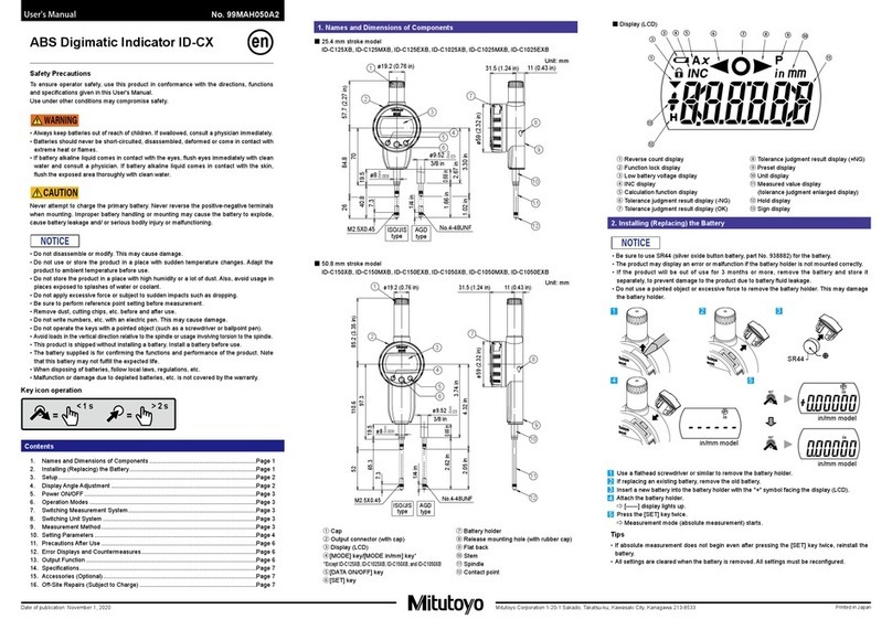
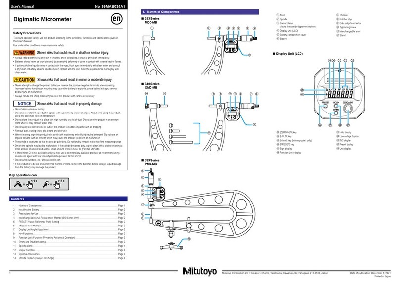
8. Button Functions
■ Power ON/OFF: [ON/OFF in/mm] Button
• Press the [ON/OFF in/mm] button.
⇨ Power turns ON.
• Press and hold the [ON/OFF in/mm] button.
⇨ Power turns OFF.
ON/OFF
■ Switching Measurement Type/Displayed Value Zero Reset: [ZERO/ABS] Button
• Press the [ZERO/ABS] button.
⇨ [INC] display lights up and the display is set to zero (incremental measurement).
• Press and hold the [ZERO/ABS] button.
⇨ [ INC] display turns off and the length from the reference point (anvil measurement surface) is
displayed (absolute measurement).
ZERO/ABS
■ Display Value Hold: [HOLD] button
• Press the [HOLD] button.
⇨ [H] display lights up and the displayed value is held.
The displayed value will not change even if the spindle moves.
• Press the [HOLD] button.
⇨ [H] display turns off and the hold is released.
The current spindle position is displayed.
HOLD
■ Unit Switching (only for in/mm model): [ON/OFF in/mm] Button
• Press the [ON/OFF in/mm] button with the power ON.
⇨ Units will switch.
ON/OFF
9. Function Lock Function (Mistaken Operation Prevention)
This product has a Function Lock function in order to avoid accidental changes to the reference
point position.
Setting the Function Lock causes the [ ] LCD to light up and disables the [PRESET] button,
[ZERO/ABS] button, and in/mm button (export specications only), with only the "Hold Operation"
and "Power ON/OFF Operation" functions enabled.
● Function Lock Function ON/OFF
• First press and hold the [HOLD] button, and then additionally press and hold the [ZERO/ABS] button.
⇨ [H] display and [ ] display light up in sequence ([H] turns off rst).
HOLD ZERO/ABS
• First press and hold the [HOLD] button, and then additionally press and hold the [ZERO/ABS] button.
⇨ [ ] display turns off and the Function Lock function is released
HOLD ZERO/ABS
10. Errors and Troubleshooting
Error Display Causes and Countermeasures
Display Overflow
The displayed value exceeds the number of digits that can be
displayed.
Normal counting will start again when the thimble is moved in
reverse and the displayed value returns to the number of digits
that can be displayed.
ABS Synthesis Error
Although this may be momentarily displayed while the spindle is
moving, it is a normal artifact of internal processing. If it occurs
while the spindle is not moving, the internal sensor has failed.
In this case, repair is required: consult with your dealer or agent or
with our sales office.
Power Voltage Drop
Battery is depleted.
Replace with a new battery.
Hardware Error
A hardware error was generated. In this case, repair is required:
consult with your dealer or agent or with our sales office.
Sensor Contamination
Detection Error
A sudden change in temperature may create condensation on the
detector, or it may be contaminated by other sources.
• Turn the power OFF and allow the product to adapt to the
temperature for about 2 hours.
• If it does not recover after adapting to the temperature, repair is
required: consult with your dealer or agent or with our sales office.
11. Specications
■ Individual Specications
● CLM-QMX
Measurement range : 0 to 15 mm, 15 to 30 mm, 0 to 0.6 in, 0.6 to 1.2 in (0.5 N to 2.5 N type)
:
0 to 10 mm, 10 to 20 mm, 20 to 30 mm, 0 to 0.4 in, 0.6 to 0.8 in, 0.8 to 1.2 in
(2 N to 10 N type)
Instrument error *1 : ±0.002 mm
● CLM-DKX
Measurement range : 0 to 15 mm, 0 to 0.6 in (0.5 N to 2.5 N type)
: 0 to 10 mm, 0 to 0.4 in (2 N to 10 N type)
Instrument error *1 : ±0.004 mm
*1: At 20 °C, excluding quantization error
■ Common Specications
Resolution : 0.001 mm, 0.00005 in
Quantization error : ±1 count
Measuring force : 0.5 to 2.5 N, variable (0.5 N to 2.5 N type)
: 2 N to 10 N, variable (2 N to 10 N type)
Measuring force scale : 0.5, 1.0, 1.5, 2.0, 2.5 N (0.5 N to 2.5 N type)
: 2, 4, 6, 8, 10 N (2 N to 10 N type)
Measuring force variation : 0.1 N or less (0.5 N to 2.5 N type)
: 0.4 N or less (2 N to 10 N type)
Set measuring force error : ±(0.1 + set measuring force/10) N (0.5 N to 2.5 N type)
: ±(0.4 + set measuring force/10) N (2 N to 10 N type)
Display : LCD (6-digit and minus sign)
Power supply : Button type silver-oxide battery (SR44 No.938882), x1
Battery life : With typical use approximately 5 years, with continuous use 18,000
hours or more
Measurement orientation : Horizontal/lateral orientation only (tilt within ±3 ° recommended)
Temperature range : 5 °C to 40 °C (operating temperature), -10 °C to 60 °C (storage
temperature)
Standard accessories : Slotted screwdriver (Part No. 210183)
Standard bar (CLM1-30QMX, CLM2-30QMX only)
Gauge block (CLM2-10QMX only)
12. Output Function
■ Display Value External Output
The displayed value can be output to a device by connecting the product and the external device
with a connection cable (option).
• Always use the 0-size Phillips screwdriver (No.05CZA619) included with the connection cable
(option) when installing/removing screws, and tighten to a torque of 5 to 8 cN • m· or so.
•
Install so that the seal does not protrude. Waterproof functioning will decrease if not installed correctly.
Install connection cables using the following procedure.
1 Use the Phillips screwdriver included with the connection cable to remove the cover xing screws
(M1.7 x 0.35 x 2.5, No.04AAB543).
2 Remove the cover.
3 Check that the connector seal (No.04AAC126) is correctly installed at the proper position (do
not remove the connector seal).
4 Mount the connection cable plug.
5 Hold the plug manually so that there is no gap between the plug and the Quickmike body, and
fasten using the xing screws on the plug.
Connector
seal
■ Output Data Format
(1) Output order
(2) All "F"
(3) Sign
(4) Measured
value
(5) Decimal
point
(6) Unit
■ Timing Chart
200 msec
140 µsec (Typ:122 µsec)
140 µsec (Typ:122 µsec)
270 µsec (Typ:244 µsec)
0 msec
100 µsec
100 µsec
100 µsec
T1
T2
T3
T4
*1: DATAsw is LOW while the data output button is being pressed.
*2: The time T5 until DATAsw goes to the LOW level and REQ is input is determined by the data
processing device performance.
13. Options
• Connection cable: No.05CZA662 (1 m)
• Connection cable: No.05CZA663 (2 m)
14. Off-Site Repairs (Subject to Charge)
Off-site repair (subject to charge) is required in the case of the following malfunctions. Contact your
nearest dealer or our sales ofce.
• Faulty spindle operation
If the spindle is scratched, these scratches may interfere while the spindle is retracting, causing
faulty operation.
Operation may also suffer if the spindle is rusted.
• Inconsistent measured values
If a shock is applied to the measurement surfaces, or if burrs appear on the measurement
surfaces. This may affect accuracy.
• Count value error/faulty operation
If the thimble of this product is retracted too far, the internal sensor will be damaged. This may
cause count errors or faulty operation.
(1)
MSD LSD
(5)
(2) (4)
(3)
+: 0(0000)
3(1100)
4(0010)
5(1010)
(6)
mm:0(0000)
