At pressures below a few Torr, there is no danger in
measuring pressure of gases other than N2and air,
merely inaccurate readings. A danger arises if the N2
calibration is used without correction to measure higher
pressure levels of some other gases. For example, N2at
24 Torr causes the same heat loss from the Convectron
sensor as argon will at atmospheric pressure. If the
pressure indication of the Convectron Gauge is not
properly corrected for argon, an operator attempting to fill
a vacuum system with 1/2 atmosphere of argon would
observe a pressure reading of only 12 Torr when the
actual pressure had risen to the desired 380 Torr.
Continuing to fill the system with argon to 760 Torr would
result in a 24 Torr pressure reading.
Depending on the pressure of the argon gas source, the
chamber could be dangerously pressurized while the
display continued to read about 30 Torr of N2equivalent
pressure.
This type of danger is not unique to the Convectron
Gauge and likely exists with other thermal conductivity
gauges using convection to extend the range to high
pressures.
To measure the pressure of gases other than air or N2
with a Convectron Gauge calibrated for N2, you must use
the conversion curves listed specifically for Convectron
Gauges to translate between indicated pressure and true
pressure. Do not use other data. Never use the
conversion curves designed for Convectron Gauges to
translate pressure readings for gauges made by other
manufacturers. Their geometry is very likely different and
dangerously high pressures may be produced even at
relatively low pressure indications.
Ensure that the atmosphere adjustments for the
Convectron Gauge are correctly set.
Use the following graphs to determine the indicated N2or
air pressure that corresponds to a specific true pressure
of 10 other commonly used process gases. Find the
point at which the horizontal line representing true
pressure intercepts the vertical line representing
indicated N2pressure. If the gas being used is not
included among those listed, or for a gas mixture,
generate a calibration curve using a gas-independent
transfer standard such as a capacitance manometer.
More thorough information is given in the Instruction
Manual, p/n 275512, which can be downloaded at:
www.mksinst.com.
Figure 12: True Pressure vs. Indicated Pressure for
Commonly used Gases, 10-4 to 10-1 Torr
Figure 13: True Pressure vs. Indicated Pressure for
Commonly used Gases, 10-1 to 1000 Torr
Figure 14: True Pressure vs. Indicated Pressure for
Commonly used Gases, 10-1 to 1000 Torr
Configure the Setpoint Relays
To measure the pressure of a gas other than N2or air,
the relay setpoints must be adjusted for the process gas.
The true pressure of a gas other than N2or air may be
substantially different from the pressure that the output
indicates. For example, outputs might indicate a
pressure of 10 Torr (1.33 kPa, 13.3 mbar) for argon,
although the true pressure of the argon is 250 Torr (33.3
kPa, 333.3 mbar). Such a substantial difference between
indicated pressure and true pressure can cause over-
pressurization resulting in an explosion.
See the Operation Chapter in the Instruction Manual
275512 for detailed instructions to adjust the setpoints.
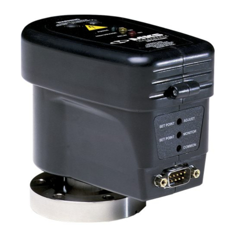
Table 2: Front Panel Features of Mini-Convectron
Module (See Figure 2)
Example Test Point Voltage: 0.64 V equals 40 mTorr
(5.3x10⁻³ kPa, 5.3x10⁻² mbar) of N2or Air
Example Test Point Voltage: 4.8 V equals 40 Torr
(5.33 kPa, 53.3 mbar) of N2or Air
Table 3: Front Panel Features of Mini-Convectron
Module with Digital Display (See Figure 3)
Nonlinear Analog Output Signal
The analog output produces a nonlinear voltage that
corresponds to measured pressure. Output voltage is
measured across pins 5 and 8 if the module has one
setpoint relay, or across pins 5 and 6 if the module has
two setpoint relays.
The vacuum chamber pressure indicated by the gauge
depends on the gas type, gas density (pressure), and the
module orientation. The module is factory calibrated for
N2(air has approximately the same calibration). For
gases other than N2or air, heat loss varies at any given
pressure, and an appropriate conversion factor must be
applied.
See “Nonlinear Analog Output” in the Operation Chapter
of the Instruction Manual, p/n 275512.
Figure 15: Non-linear Analog Output Curves
Calibration at Atmosphere and Vacuum
Pressures
Calibration improves the accuracy and repeatability of
the Convectron gauge.
An atmospheric calibration is performed on the
Convectron gauge, using N2, at the factory before the
module is shipped. The factory calibration sets the
atmospheric calibration point to 760 Torr (101.3 kPa, 1013
mbar) of N2.
Because performance varies depending on the process
gas, it may be necessary to reset the atmospheric
calibration point if a gas other than N2or air is being
used. Periodic resets of the atmospheric calibration point
also improve the accuracy and repeatability of the
Convectron gauge near atmospheric pressure, even if
the process gas is N2or air.
During a fast pumpdown from atmospheric pressure,
thermal effects temporarily prevent the module from
measuring pressure accurately below 1 x 10⁻³ Torr
(1.3 x 10⁻⁴ kPa, 1.3 x 10⁻³ mbar). After approximately 15
minutes, pressure indications the 1 x 10⁻⁴ Torr
(1.3 x 10⁻⁵ kPa, 1.3 x 10⁻⁴ mbar) range will be accurate.
When pressure indication in the 1 x 10⁻⁴ Torr (1.3 x 10⁻⁵
kPa, 1.3 x 10⁻⁴ mbar) range has stabilized, a Convectron
gauge calibration at vacuum chamber pressure may be
performed.
The calibration may be performed at a higher pressure if
readings in the 1 x 10⁻⁴ Torr (1.3 x 10⁻⁵ kPa, 1.3 x 10⁻⁴ mbar)
range are not required. In the 1 x 10⁻⁴ Torr
(1.3 x 10⁻⁵ kPa, 1.3 x 10⁻⁴ mbar) range, resolution is ±0.1
millitorr, if the Convectron gauge has been properly
calibrated at vacuum chamber pressure. If the module
frequently operates in the 1 x 10⁻⁴ Torr (1.3 x 10⁻⁵ kPa, 1.3 x
10–4 mbar) range, Convectron gauge calibration at
vacuum chamber pressure should be performed
frequently.
See “Calibrating Convectron Gauge at Atmospheric
Pressure” and “Calibrating Convectron Gauge at
Vacuum Chamber Pressure” in the Operation Chapter of
the Instruction Manual, p/n 275512.
Product Specifications
1. Measurements will change with different gases and mixtures.
Correction parameters must be used for gases other than N2
or Air.
2. Do not use Convectron Gauges with flammable or explosive
gases.
Declaration of Conformity
Chinese Hazardous Substances
Concentration Table
Service / Maintenance
If the product requires service, contact the MKS,
Granville-Phillips Technical Support Department at
1-303-652-4400 for troubleshooting help.
If the product must be returned to the factory for service,
request a Return Material Authorization (RMA) from
Granville-Phillips. Do not return products without first
obtaining an RMA. Insome cases a hazardous materials
document may be required. The MKS/Granville-Phillips
Customer Service Representative will advise you if the
hazardous materials document is required.
When returning a product to Granville-Phillips, be sure to
package the product to prevent shipping damage. Circuit
boards and modules separated from the gauge assembly
must be handled using proper anti-static protection
methods and must be packaged in anti-static packaging.
Shipping damage on returned products as a result of
inadequate packaging is the Buyer's responsibility.
Service / Maintenance Procedures
Troubleshooting and gauge replacement instructions are
given in the Instruction Manual, p/n 275512, which can
be downloaded at: www.mksinst.com.
Customer Service / Technical Support
MKS Pressure and Vacuum Measurement Solutions
MKS Instruments, Inc., Granville-Phillips®Division
6450 Dry Creek Parkway
Longmont, Colorado 80503 USA
Tel: 303-652-4400
Fax: 303-652-2844
MKS Corporate Headquarters
MKS Instruments, Inc.
2 Tech Drive, Suite 201
Andover, MA 01810 USA
Tel: 978-645-5500
Fax: 978-557-5100
Feature Description
ADJUST ATMOSPHERE
potentiometer
Enables Convectron gauge
calibration at atmospheric pressure
ADJUST VACUUM
potentiometer
Enables Convectron gauge
calibration at vacuum chamber
pressure
ADJUST SET PT1 and
ADJUST SET PT2
potentiometers
Enables setting of vacuum pressure
at which setpoint relays activate
MONITOR ANALOG test
point
Enables reading of analog output
voltage representing measured
pressure
MONITOR COMMON
test point
Enable checking of values for:
• Convectron gauge calibration at
atmospheric pressure
• Convectron gauge calibration at
vacuum chamber pressure
MONITOR SET PT1 and
MONITOR SET PT2 test
points
Enables checking of setpoint relay
voltage representing measured
pressure. See the 2 examples,
below.
P>100MT LED Turns solid red when pressure is
>100 mTorr
Feature Description
ADJUST ATM
potentiometer
Enables Convectron gauge
calibration at atmospheric pressure
ADJUST VAC
potentiometer
Enables Convectron gauge
calibration at vacuum chamber
pressure
S.P. ADJUST SET switch Enables choosing of setpoint relay
1 or setpoint relay 2 for adjustment
• Press the switch once to adjust
setpoint relay 1
• Press the switch twice to adjust
setpoint relay 2
S.P. ADJUST DOWN
switch
Enables downward adjustment of
setpoint 1 or setpoint 2
S.P. ADJUST UP switch Enables upward adjustment of
setpoint 1 or setpoint 2
Pressure value display Provides 3-digit indication of
measured pressure
TORR and mTORR LEDs • TORR is solid green when 3-
digit display indicates pressure
in Torr
• mTORR is solid green when 3-
digit display indicates pressure
in mTorr
RELAY ON SP1 and
RELAY ON SP2 LEDs
• RELAY ON SP1 is solid green
when setpoint relay 1 is
activated
• RELAY ON SP1 blinks green if
S.P. ADJUST SET switch has
been pressed once
• RELAY ON SP2 is solid green
when setpoint relay 2 is
activated
• RELAY ON SP2 blinks green if
S.P. ADJUST SET switch has
been pressed twice
Parameter Specification
Measurement Range for
N2/ Air 1,2 See notes 1 and 2, below
Torr 1x10⁻⁴ to 1000 Torr
mbar 1x10⁻⁴ to 1300 mbar
pascal 1x10⁻² to 130 kPa
Setpoint relays Single-pole, double-throw (SPDT)
Contact rating 1 A @ 30 Vdc resistive, 30 VAC non-inductive
Hysteresis 2% of reading for module without display;
10% of reading plus 1 significant digit for
module with optional display
Resolution 2 significant digits
Analog output signal 0.375 to 5.659 Vdc for 0 to 1000 Torr of N2,
non-linear;
0 to 1333 mbar of N2, non-linear;
0 to 1.33 x 10⁻¹ kPa of N2, non-linear
Mini-Convectron Module
Mounting orientation Horizontal preferred
Input power
With optional display 11.5 to 26.5 Vdc, 0.15 A at 11.5 Vdc, 3.5 W
maximum
Without display 11.5 to 26.5 Vdc, 0.1 A at 11.5 Vdc, 1.6 W
maximum
I/O connectors
2 setpoint relays 15-pin male, high-density subminiature D
1 setpoint relay 9-pin male, subminiature D
Operating temperature 0 oC to +40 oC (32 0F to 104 0F) ambient,
indoor use only, ordinary protection from
moisture
Non-operating
temperature -40 oC to +70 oC (-40 0F to 158 0F)
Case material Powder-coated extruded aluminum
Weight 340 g (12 oz.) with 1/8 NPT fitting
CE Compliance
EMC EN61326-1
Safety EN61010-1
IP rating IP20
Convectron Gauge
Sensing wire filament Gold-plated tungsten (standard)
or solid platinum (optional)
Internal volume 40 cc (2.5 cu. in.)
Materials exposed to
gas 304 Stainless Steel, 17-7 stainless steel,
ceramic, Ag/Cu brazing material, Kovar,
alumina, and molybdenum
Bakeout temperature 150 oC (302 oC) maximum, non-operating,
with electronics removed
Specifications and dimensions are subject to change without notice. © 2016 MKS Instruments, Inc. All rights reserved.
Granville-Phillips®, Convectron®, and Mini-Convectron®are
registered trademarks, and mksinstTM is a trademark of MKS
Instruments, Inc. All other trademarks and registered trademarks
are the properties of their respective owners.
Quick Start Guide p/n 275002-Rev. B
October 2016 Template p/n DR100019-Rev. F
More detailed instructions regarding
installation, operation, and service of the
Series 275 Mini-Convectron Module are
provided in the Instruction Manual, p/n
275512, available online at
www.mksinst.com.
Notice

