manuals.online logo
Brands
  1. Home
  2. •
  3. Brands
  4. •
  5. Monacor
  6. •
  7. Control Unit
  8. •
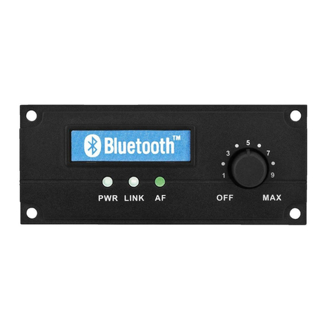
  9. Monacor img Stage Line TXS-820M User manual

Monacor img Stage Line TXS-820M User manual

Empfangsmodul für
863,05 MHz oder
864,80 MHz
Bitte lesen Sie diese Anleitung vor der Inbetrieb-
nahme gründlich durch und heben Sie sie für ein
späteres Nachlesen auf.
1 Einsatzmöglichkeiten
Dieses Empfangsmodul dient zum nachträglichen
Einbau z. B in einen Verstärker, eine Aktivbox oder
in ein Mischpult. Es empfängt die Signale eines
Funkmikrofons aus der Serie TXS-82… von „img
Stage Line“.
Für den Betrieb wird eine 8-V-Gleichspannung
benötigt. Es lassen sich ein Feldstärke-Instrument,
eine LED zur Anzeige eines empfangenen Träger-
signals und ein Squelch-Regler anschließen.
2 Wichtige Hinweise zum sicheren Gebrauch
GDas Modul ist nach der EMV-Richtlinie 2014/
30/EG (EMV = Elektromagnetische Verträg-
lichkeit) aufgebaut. Damit es auch im Betrieb
diese Richtlinie erfüllt, muss es in ein abge-
schirmtes Gehäuse eingesetzt und der Audio-
ausgang über eine abgeschirmte Leitung ange-
schlossen werden. Wird die EMV-Richtlinie
nicht eingehalten, erlischt die Konformitätser-
klärung.
GSchützen Sie das Modul vor Tropf- und Spritz-
wasser, hoher Luftfeuchtigkeit und Hitze (zu-
lässiger Einsatztemperaturbereich 0 – 40 °C).
GWird das Modul zweckentfremdet, falsch ange-
schlossen oder nicht fachgerecht repariert,
kann keine Haftung für daraus resultierende
Sach- oder Personenschäden und keine
Garantie für das Modul übernommen werden.
3 Anschluss und Inbetriebnahme
1) Das Modul über die 6-polige Buchse (4) ent-
sprechend der Abb. 1 anschließen:
2) Soll die Squelch-Einstellung über ein separa-
tes Potentiometer erfolgen, nach Abb. 1 die
drei Bauelemente in der gestrichelten Umran-
Pin nach Abb. 1 Funktion
1 Masse
2 Audioausgang
3 externer Squelch-Regler
4 LED für Trägeranzeige
5 Instrument für Feldstärke
6 Betriebsspannung +8 V, 90 mA
Soll das Modul endgültig aus dem Betrieb
genommen werden, übergeben Sie es
zur umweltgerechten Entsorgung einem
örtlichen Recyclingbetrieb.
dung anschließen und den DIP-Schalter SQ
(2) in die untere Position „aus“ stellen.
Soll die Squelch-Ansprechschwelle mit dem
internen Potentiometer (3) eingestellt werden,
dürfen die drei Bauelemente in der gestrichelten
Umrandung nicht angeschlossen sein! Den DIP-
Schalter SQ in die obere Position ON stellen.
3) Eine Antenne mit der entsprechenden Emp-
fangsfrequenz an die Buchse (1) anschließen.
4) Zum Unterdrücken von Ein- und Ausschaltge-
räuschen den DIP-Schalter TONE (2) in die
Position ON stellen.
5) Zum Einstellen der Squelch-Ansprechschwelle
einen passenden Sender einschalten. Das ex-
terne Squelch-Potentiometer (P1) oder das
interne (3) so einstellen, dass die angeschlos-
sene LED (LD1) leuchtet.
4 Technische Daten
Empfangsfrequenz
TXS-820M: . . . . . . . . . 863,05 MHz
TXS-822M: . . . . . . . . . 864,80 MHz
Empfangssystem: . . . . . . Non-Diversity
Audioausgang: . . . . . . . . max. 1,5 V
Betriebsspannung: . . . . . 8 V, 90 mA
Abmessungen: . . . . . . . . 120 × 15 × 57 mm
Änderungen vorbehalten.
Receiving Module for
863.05 MHz or 864.80 MHz
Please read these instructions carefully prior to
setting the unit into operation and keep them for
later use.
1 Applications
This receiving module serves for subsequent
installation e. g. into an amplifier, an active speak-
er system, or a mixer. It receives the signals of a
wireless microphone of the series TXS-82... from
“img Stage Line”.
For the operation an 8 V direct voltage is re-
quired. It is possible to connect a field strength
meter, an LED to indicate a received carrier signal,
and a squelch control.
2 Important Safety Notes
GThe module has been set up according to the
directive 2014/30/EC for electromagnetic com-
patibility. In order to comply with this directive
also during operation, it must be placed into a
screened housing and the audio output must be
connected via a screened cable. If the directive
for electromagnetic compatibility is not com-
plied with, the declaration of conformity will
expire.
GProtect the module against dripping water and
splash water, high air humidity, and heat (ad-
missible ambient temperature range 0 – 40 °C).
GNo guarantee claims for the module and no lia-
bility for any resulting personal damage or
material damage will be accepted if the module
is used for other purposes than originally in-
tended, if it is not correctly connected or not re-
paired in an expert way.
3 Connection and Setting into Operation
1) Connect the module via the 6-pole jack (4)
according to fig. 1:
2) For adjusting the squelch threshold via a sep-
arate potentiometer, connect the three compo-
Pin acc. to fig. 1 Function
1 ground
2 audio output
3 external squelch control
4 LED for carrier indication
5 meter for field strength
6 operating voltage +8 V, 90 mA
If the module is to be put out of operation
definitively, take it to a local recycling
plant for a disposal which is not harmful
to the environment.
nents within the dashed lines according to fig. 1
and set the DIP switch SQ (2) to the lower posi-
tion “off”.
For adjusting the squelch threshold with the
internal potentiometer (3), the three compo-
nents within the dashed lines must not be con-
nected! Set the DIP switch SQ to the upper
position ON.
3) Connect an antenna with the corresponding
receiving frequency to the jack (1).
4) To suppress noise when switching on and off,
set the DIP switch TONE (2) to position ON.
5) To adjust the squelch threshold, switch on a
matching transmitter. Adjust the external squelch
potentiometer (P1) or the internal potentiometer
(3) so that the connected LED (LD1) lights up.
4 Specifications
Receiving frequency
TXS-820M: . . . . . . . . . 863.05 MHz
TXS-822M: . . . . . . . . . 864.80 MHz
Receiving system: . . . . . non-diversity
Audio output: . . . . . . . . . max. 1.5 V
Operating voltage: . . . . . 8 V, 90 mA
Dimensions: . . . . . . . . . . 120 × 15 × 57 mm
Subject to technical modification.
TXS-820M
Bestell-Nr. 24.4470
wwwwww..iimmggssttaaggeelliinnee..ccoomm
TXS-822M
Bestell-Nr. 24.4480
®
MONACOR INTERNATIONAL GmbH & Co. KG
•
Zum Falsch 36
•
28307 Bremen
•
Germany
Copyright
©by MONACOR INTERNATIONAL. All rights reserved. A-0488.99.03.06.2014
GND
AF
SQ
LED
RSSI
+8V
1
6
SQTONE
A
56k 560
LD1
+8 V
Audio
47k
P1
20k
4k7
ON
12
100 μA
An .
ON
12
1234

nur bei externer
Squelch-Einstellung
for external squelch
adjustment only
Squelch intern • internal
Squelch extern • external
Ein-/Ausschalt-Muting:
Muting of switching noise:
ein • on
aus • off
Squelch
intern
internal
GB
D A CH
Module de réception
pour 863,05 MHz ou
864,80 MHZ
Veuillez lire la présente notice avec attention
avant le fonctionnement et conservez-la pour pou-
voir vous y reporter ultérieurement.
1 Possibilités dʼutilisation
Ce module de réception sert pour un montage
ultérieur par exemple dans un amplificateur, une
enceinte active ou une table de mixage. Il reçoit
les signaux dʼun microphone sans fil de la série
TXS-82... de “img Stage Line”.
Pour le fonctionnement, une tension continue
8 V est nécessaire. On peut connecter un appareil
de mesure dʼintensité de champ, une LED dʼindica-
tion dʼun signal porteur reçu et un réglage squelch.
2 Conseils importants dʼutilisation
et de sécurité
GLe module est conçu selon la directive 2014/
30/CE relative à la compatibilité électromagné-
tique. Pour quʼil réponde aux exigences de cet-
te directive pendant son fonctionnement, il doit
être placé dans un boîtier blindé et la sortie
audio doit être reliée via un câble blindé. Si la
directive CEM nʼest pas respectée, lʼappareil
perd toute déclaration de conformité.
GProtégez le module de tout type de projections
dʼeau, des éclaboussures, dʼune humidité éle-
vée et de la chaleur (plage de température de
fonctionnement autorisée : 0 – 40 °C).
GNous déclinons toute responsabilité en cas de
dommages matériels ou corporels consécutifs
si le module est utilisé dans un but autre que
celui pour lequel il a été conçu, sʼil nʼest pas
correctement branché, ou nʼest pas réparé par
une personne habilitée ; de même, la garantie
deviendrait caduque.
3 Branchement et fonctionnement
1) Connectez le module via la prise 6 pôles (4)
selon le schéma 1 :
2) Si le seuil de déclenchement du squelch doit
être réglé via un potentiomètre séparé, reliez
Pin (schéma 1) Fonction
1 Masse
2 Sortie audio
3 Réglage squelch externe
4 LED pour affichage porteuse
5
Appareil de mesure dʼintensité de champ
6
Tension de fonctionnement +8 V, 90 mA
Lorsque le module est définitivement retiré
du service, vous devez le déposer dans
une usine de recyclage adaptée pour
contribuer à son élimination non polluante.
les trois composants dans les lignes pointillées
selon le schéma 1 et mettez lʼinterrupteur DIP
SQ (2) sur la position inférieure “off”.
Si le seuil de déclenchement du squelch doit
être réglé avec le potentiomètre interne (3), les
trois composants dans les lignes pointillées ne
devraient pas être reliés! Mettez lʼinterrupteur
DIP SQ sur la position supérieure ON.
3) Reliez une antenne avec la fréquence de
réception correspondante à la prise (1).
4) Pour supprimer les bruits dʼallumage et dʼex-
tinction, mettez lʼinterrupteur DIP TONE (2) sur
la position ON.
5) Pour régler le seuil de déclenchement du
squelch, allumez un émetteur correspondant.
Réglez le potentiomètre externe squelch (P1)
ou le potentiomètre interne (3) de telle sorte
que la LED reliée (1) brille.
4 Caractéristiques techniques
Fréquence de réception
TXS-820M : . . . . . . . . 863,05 MHz
TXS-822M : . . . . . . . . 864,80 MHz
Système de réception : . non diversity
Sortie audio : . . . . . . . . . 1,5 V max.
Tension de fonc. : . . . . . . 8 V, 90 mA
Dimensions : . . . . . . . . . . 120 × 15 × 57 mm
Tout droit de modification réservé.
Modulo di ricezione per
863,05 MHz o 864,80 MHz
Vi preghiamo di leggere attentamente le presenti
istruzioni prima della messa in funzione e di con-
servarle per un uso futuro.
1 Possibilità dʼimpiego
Questo modulo di ricezione serve per il montaggio
in un secondo tempo, p. es. in un amplificatore,
una cassa attiva o in un mixer. Riceve i segnali di
un radiomicrofono della serie TXS-82… di “img
Stage Line”.
Per il funzionamento è richiesta una tensione
continua di 8 V. Si possono collegare uno stru-
mento dʼintensità di campo, un LED per indicare
la ricezione di un segnale della portante e un rego-
latore squelch.
2 Avvertenze importanti di sicurezza
GIl modulo è costruito seconda la direttiva EMC
2014/30/CE (EMC = compatibilità elettroma-
gnetica). Perché sia conforme a questa diret-
tiva anche durante il funzionamento, deve es-
sere inserito in un contenitore schermato, e
lʼuscita audio deve essere collegata per mezzo
di un cavo schermato. Se la direttiva EMC non
viene rispettata, la dichiarazione di conformità
diventa nulla.
GProteggere il modulo dallʼacqua gocciolante e
dagli spruzzi dʼacqua, da alta umidità dellʼaria e
dal calore (temperatura dʼimpiego ammessa fra
0 e 40 °C).
GNel caso dʼuso improprio, di collegamenti sba-
gliati o di riparazione non a regola dʼarte del
modulo, non si assume nessuna responsabilità
per eventuali danni consequenziali a persone o
a cose e non si assume nessuna garanzia per
il modulo.
3 Collegamento e messa in funzione
1) Collegare il modulo per mezzo della presa a
6 poli (4) come da fig. 1:
2) Se la regolazione squelch deve essere fatta
attraverso un potenziometro esterno, collegare
Pin (schéma 1) Funzione
1 Massa
2 Uscita audio
3 Regolatore esterno squelch
4 LED per indicazione portante
5 Strumento per intensità di campo
6 Tensione dʼesercizio +8 V, 90 mA
Se si desidera eliminare il modulo defini-
tivamente, consegnarlo per lo smalti-
mento ad unʼistituzione locale per il rici-
claggio.
i tre elementi raggruppati nella cornice tratteg-
giata secondo fig. 1 e portare il DIP-switch
SQ (2) in posizione inferiore “off”.
Se la soglia di reazione squelch deve essere
impostata con il potenziometro interno (3), i tre
elementi nella cornice tratteggiata non devono
essere collegati! Portare il DIP-switch SQ in
posizione superiore ON.
3) Collegare unʼantenna con frequenza di rice-
zione adatta alla presa (1).
4) Per sopprimere rumori di commutazione, por-
tare il DIP-switch TONE (2) in posizione ON.
5) Per impostare la soglia di reazione squelch,
accendere una trasmittente adatta. Regolare il
potenziometro squelch esterno (P1) o interno
(3) in modo tale che il LED (LD1) collegato si
accenda.
4 Dati tecnici
Frequenza di ricezione
TXS-820M: . . . . . . . . . 863,05 MHz
TXS-822M: . . . . . . . . . 864,80 MHz
Sistema di ricezione . . . . non-diversity
Uscita audio: . . . . . . . . . . max. 1,5 V
Tensione dʼesercizio: . . . 8 V, 90 mA
Dimensioni: . . . . . . . . . . . 120 × 15 × 57 mm
Con riserva di modifiche tecniche.
TXS-820M
Bestell-Nr. 24.4470
wwwwww..iimmggssttaaggeelliinnee..ccoomm
TXS-822M
Bestell-Nr. 24.4480
®
MONACOR INTERNATIONAL GmbH & Co. KG
•
Zum Falsch 36
•
28307 Bremen
•
Germany
Copyright
©by MONACOR INTERNATIONAL. All rights reserved. A-0488.99.03.06.2014
GND
AF
SQ
LED
RSSI
+8V
1
6
SQTONE
A
56k 560
LD1
+8 V
Audio
47k
P1
20k
4k7
ON
12
100 μA
An .
ON
12
1 234 
uniquement pour réglage
externe du squelch
solo con impostazione
squelch esterna
Squelch interne • interno
Squelch externe • esterno
Marche/arrêt coupure du son :
Muting ON/OFF:
marche • on
arrêt • off
Squelch
interne
interno
F B CH
I
Módulo receptor para
863,05 MHz o 864,80 MHz
Por favor, lea estas instrucciones cuidadosamen-
te antes de poner el aparato en funcionamiento y
guárdelas para su uso posterior.
1 Aplicaciones
Este módulo receptor sirve para la instalación
posterior, por ejemplo, en un amplificador, un sis-
tema activo de altavoz, o un mezclador. Recibe
las señales de un micrófono sin cable de la serie
TXS-82... de “img Stage Line”.
Para el funcionamiento se requiere una
corriente directa de 8 V. Es posible conectar un
instrumento de intensidad de campo, un LED para
indicar una señal de portadora recibida, y un con-
trol del silenciador.
2 Consejos de seguridad importantes
GEl módulo ha sido instalado de acuerdo con la
Directiva 2014/30/CE para la compatibilidad
electromagnética. Para cumplir con esta Direc-
tiva también durante el funcionamiento, debe
ser colocado en una caja blindada y la salida
audio se debe conectar a través del cable blin-
dado. Si la Directiva para la compatibilidad
electromagnética no se respeta, la declaración
de conformidad expirará.
GProteja el módulo de cualquier tipo de proyec-
ciones de agua, salpicaduras, humedad ele-
vada, y calor (temperatura de utilización admi-
sible 0 – 40 °C).
GNo se admitirá ninguna exigencia de garantía
para el módulo y ni se asumirá ninguna respon-
sabilidad en caso de daños personales o mate-
riales si el módulo es utilizado para otro fin dis-
tinto a aquél para el que fue concebido, si no es
correctamente conectado o si no es reparado
por personal habilitado de manera adecuada.
3 Conexión y puesta en marcha
1) Conecte el módulo a través del jack de 6 polos
(4) como muestra la imagen 1:
2) Para ajustar el umbral del silenciador a través
de un potenciómetro independiente, conecte
Pin (imagen 1) Función
1 Masa
2 Salida audio
3 Control externo del silenciador
4 LED indicador del portador
5 Medidor de intensidad de campo
6Voltaje de funcionamiento +8 V, 90 mA
Si el módulo va a ser retirado definitiva-
mente del uso, llévelo a un centro de reci-
claje próximo para su eliminación no con-
taminante.
los tres componentes dentro de las líneas dis-
continuas según la imagen 1 y ponga el inte-
rruptor DIP SQ (2) en la posición inferior “apa-
gado”.
¡Para ajustar el umbral del silenciador con el
potenciómetro interno (3), los tres componen-
tes dentro de las líneas discontinuas no deben
estar conectados! Ponga el interruptor DIP SQ
en la posición superior ON.
3) Conecte al jack (1) una antena con la frecuen-
cia de recepción que corresponda.
4) Para suprimir ruido de conmutación, ponga el
interruptor DIP TONE (2) en la posición ON.
5) Para ajustar el umbral del silenciador, conecte
un transmisor adecuado. Ajuste el potenció-
metro del silenciador externo (P1) o el poten-
ciómetro interno (3) de modo que el LED
conectado (LD1) se encienda.
4 Características técnicas
Frecuencia de recepción
TXS-820M: . . . . . . . . . 863,05 MHz
TXS-822M: . . . . . . . . . 864,80 MHz
Sistema receptor: . . . . . . non-diversity
Salida audio: . . . . . . . . . máx. 1,5 V
Voltaje de func.: . . . . . . . 8 V, 90 mA
Dimensiones: . . . . . . . . . 120 × 15 × 57 mm
Sujeto a modificaciones técnicas.
Moduł odbiorczy
863,05 MHz lub 864,80 MHz
Prosimy o uważne przeczytanie poniższej instru-
kcji przed użyciem urządzenia, oraz o zachowanie
tekstu do wglądu.
1 Zastosowanie
Moduł odbiorczy jest przeznaczony do podłą-
czenia np. do wzmacniacza, aktywnego zestawu
głośnikowego, lub do miksera. Urządzenie służy
do odbioru sygnału dźwiękowego z mikrofonu
bezprzewodowego serii TXS-82... z oferty “img
Stage Line”.
Urządzenie jest zasilane napięciem bezpośred-
nim 8 V. Do urządzenia można podłączyć miernik
natężenia pola, wskaźnik LED sygnalizujący otrzy-
manie sygnału nośnego, oraz regulator wyciszania.
2 Bezpieczeństwo użytkowania
GUrządzenie spełnia wymogi normy o zgodności
elektromagnetycznej 2014/30/WE. Aby urządz-
enie nadal spełniało powyższe wymogi podczas
pracy, należy je zamontować w ekranowanej
obudowie, oraz należy podłączyć wyjście audio
ekranowanym kablem. Jeśli urządzenie nie
będzie spełniało wymogów normy o zgodności
elektromagnetycznej, oświadczenie o zgod-
ności z ową normą przestanie obowiązywać.
G
Należy chronić urządzenie przed działaniem
wody, wilgoci oraz wysokiej temperatury (dopusz-
czalna temperatura otoczenia pracy to 0 – 40 ºC).
GProducent ani dostawca nie ponoszą odpowie-
dzialności za wynikłe szkody (uszkodzenie
sprzętu lub obrażenia użytkownika), jeśli urzą-
dzenie było używane niezgodnie z przezna-
czeniem, jeśli zostało nieodpowiednio podłą-
czone, lub jeśli było poddawane nieautoryzo-
wanym naprawom.
3 Podłączenie urządzenia, przygotowanie
do pracy
1) Należy połączyć moduł przez gniazdo 6-pino-
we (4), zob. rys. 1:
2) Aby regulować próg wyciszania za pomocą
zewnętrznego potencjometru, należy połączyć
Piny jak na rys. 1 Funkcja
1 uziemienie
2 wyjście audio
3 zewnętrzny regulator wyciszania
4 wskaźnik LED sygnału nośnego
5 miernik natężenia pola
6 napięcie robocze +8 V, 90 mA
Jeśli urządzenie ma zostać ostatecznie
wycofane z użycia, należy przekazać je
do punktu utylizacji odpadów, aby unik-
nąć zanieczyszczenia środowiska.
3 komponenty zaznaczone linią przerywaną na
rys. 1 i ustawić mikroprzełącznik SQ (2) w dol-
nej pozycji “off”.
Aby regulować próg wyciszania za pomocą
wbudowanego potencjometru (3), nie wolno
podłączać trzech komponentów zaznaczonych
linią przerywaną! Mikroprzełącznik SQ ma się
znajdować w górnej pozycji ON.
3) Należy podłączyć do gniazda (1) antenę o
odpowiedniej częstotliwości odbiorczej.
4) Należy ustawić mikroprzełącznik TONE (2) w
pozycji ON, aby wyciszyć trzaski podczas włą-
czania i wyłączania urządzenia.
5) Aby ustawić próg wyciszania, należy włączyć
nadajnik. Należy ustawić zewnętrzny potencjo-
metr do regulacji progu wyciszania (P1) lub
wbudowany potencjometr (3), aż zapali się
podłączony wskaźnik LED (LD1).
4 Dane techniczne
Częstotliwość odbiorcza
TXS-820M: . . . . . . . . . 863,05 MHz
TXS-822M: . . . . . . . . . 864,80 MHz
System odbiorczy: . . . . . non-diversity
Wyjście audio: . . . . . . . . maks. 1,5 V
Napięcie robocze: . . . . . . 8 V, 90 mA
Wymiary: . . . . . . . . . . . . 120 × 15 × 57 mm
Z zastrzeżeniem możliwości zmian.
TXS-820M
Bestell-Nr. 24.4470
wwwwww..iimmggssttaaggeelliinnee..ccoomm
TXS-822M
Bestell-Nr. 24.4480
®
MONACOR INTERNATIONAL GmbH & Co. KG
•
Zum Falsch 36
•
28307 Bremen
•
Germany
Copyright
©by MONACOR INTERNATIONAL. All rights reserved. A-0488.99.03.06.2014

GND
AF
SQ
LED
RSSI
+8V
1
6
SQTONE
A
56k 560
LD1
+8 V
Audio
47k
P1
20k
4k7
ON
12
100 μA
An .
ON
12
1234

solamente para el ajuste
del silenciador externo
tylko zewnętrzna
regulacja wyciszania
Silenciador interno
wewnętrzne wyciszanie
Silenciador externo
zewnętrzne wyciszanie
Muting del ruido de conmutacíon:
Funkcja wyciszania trzasków
podczas włączania urządzenia:
encendido • włączona
apagado • wyłączona
Silenciador
interno
wewnętrne
wyciszanie
PL
E

This manual suits for next models

3

Other Monacor Control Unit manuals

Monacor ATT-110/SI User manual

Monacor

Monacor ATT-110/SI User manual

Monacor ATT-306PEU User manual

Monacor

Monacor ATT-306PEU User manual

Monacor ATT-506PEU User manual

Monacor

Monacor ATT-506PEU User manual

Monacor ATT-412PEU User manual

Monacor

Monacor ATT-412PEU User manual

Monacor TVCCD-30MA User manual

Monacor

Monacor TVCCD-30MA User manual

Monacor MPA-1 User manual

Monacor

Monacor MPA-1 User manual

Monacor DN-1218P User manual

Monacor

Monacor DN-1218P User manual

Monacor img Stage Line DIB-100 User manual

Monacor

Monacor img Stage Line DIB-100 User manual

Monacor ATT-212/WS User manual

Monacor

Monacor ATT-212/WS User manual

Monacor PA-1200C User manual

Monacor

Monacor PA-1200C User manual

Monacor ATT-1950 User manual

Monacor

Monacor ATT-1950 User manual

Monacor SAM-2 User manual

Monacor

Monacor SAM-2 User manual

Monacor SAM-200D User manual

Monacor

Monacor SAM-200D User manual

Monacor TXA-802MBT User manual

Monacor

Monacor TXA-802MBT User manual

Monacor ATT-210P/WS User manual

Monacor

Monacor ATT-210P/WS User manual

Monacor TVCCD-38MCOL User manual

Monacor

Monacor TVCCD-38MCOL User manual

Monacor PA TXA-802MT User manual

Monacor

Monacor PA TXA-802MT User manual

Monacor ATT-1950 User manual

Monacor

Monacor ATT-1950 User manual

Monacor ATT-325ST User manual

Monacor

Monacor ATT-325ST User manual

Monacor PA-24FMM Quick guide

Monacor

Monacor PA-24FMM Quick guide

Monacor ATT-212/WS User manual

Monacor

Monacor ATT-212/WS User manual

Monacor PA-1200EX User manual

Monacor

Monacor PA-1200EX User manual

Monacor Security SC-24 User manual

Monacor

Monacor Security SC-24 User manual

Monacor MPA-1 User manual

Monacor

Monacor MPA-1 User manual

Popular Control Unit manuals by other brands

Kelso K2AV Installation, Operation, Inspection and Maintenance Manual

Kelso

Kelso K2AV Installation, Operation, Inspection and Maintenance Manual

zipLink ZL-RTB50 installation instructions

zipLink

zipLink ZL-RTB50 installation instructions

pizzato CS MP301M0 quick start guide

pizzato

pizzato CS MP301M0 quick start guide

Vetus VRF56A installation instructions

Vetus

Vetus VRF56A installation instructions

Siemens HOTEL SOLUTION HTC3.1/A manual

Siemens

Siemens HOTEL SOLUTION HTC3.1/A manual

ISYGLT MA-IP-2 Technical Data/Instruction Manual

ISYGLT

ISYGLT MA-IP-2 Technical Data/Instruction Manual

Captron CANEO 41 Series Original operating instructions

Captron

Captron CANEO 41 Series Original operating instructions

Geco GHC201.07 Service & operating manual

Geco

Geco GHC201.07 Service & operating manual

Eaton SL7-AP Series Instruction leaflet

Eaton

Eaton SL7-AP Series Instruction leaflet

Staubli CombiTac 10Gbit Series Assembly instructions

Staubli

Staubli CombiTac 10Gbit Series Assembly instructions

Grundfos CIM 260 Installation and operating instructions

Grundfos

Grundfos CIM 260 Installation and operating instructions

Sena Parani ESD100V2 quick start guide

Sena

Sena Parani ESD100V2 quick start guide

OSF Poolcontrol-30-Vario Installation and operating instructions

OSF

OSF Poolcontrol-30-Vario Installation and operating instructions

pumpa PPC22-2P Translation of the original instruction manual

pumpa

pumpa PPC22-2P Translation of the original instruction manual

Toshiba BMS-SM1280HTLE owner's manual

Toshiba

Toshiba BMS-SM1280HTLE owner's manual

Mitsubishi Electric NZ2FTGN user manual

Mitsubishi Electric

Mitsubishi Electric NZ2FTGN user manual

Orbinox FAGERBERG EK Installation, operation & maintenance manual

Orbinox

Orbinox FAGERBERG EK Installation, operation & maintenance manual

GFA DC 8010 installation instructions

GFA

GFA DC 8010 installation instructions

manuals.online logo
manuals.online logoBrands
  • About & Mission
  • Contact us
  • Privacy Policy
  • Terms and Conditions

Copyright 2025 Manuals.Online. All Rights Reserved.