manuals.online logo
Brands
  1. Home
  2. •
  3. Brands
  4. •
  5. Monacor
  6. •
  7. Control Unit
  8. •
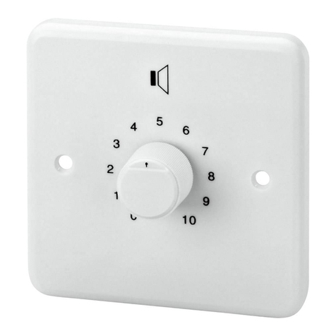
  9. Monacor ATT-412PEU User manual

Monacor ATT-412PEU User manual

ELA-Lautstärkesteller mit
Programmwähler
1Verwendungsmöglichkeiten
Der Lautstärkesteller mit Programmwähler ist speziell für den
Einsatz in ELA-Anlagen konzipiert, die mit 100-V-Technik ar-
beiten. Die maximale Nennbelastbarkeit durch den nachfol-
genden Lautsprecher bzw. durch die nachfolgende Lautspre-
chergruppe darf nicht überschritten werden – siehe
Technischen Daten.
Der Lautstärkesteller muss in eine Standard-Unterputz-
dose oder in eineAufputzdose (z.B.ATT-400 von MONACOR)
eingesetzt werden.
2Wichtige Hinweise für den sicheren Gebrauch
Das Gerät entspricht der Richtlinie für elektromagnetische Ver-
träglichkeit 89/336/EWG und der Niederspannungsrichtlinie
73/23/EWG.
●Das Gerät ist nur zur Verwendung im Innenbereich geeig-
net. Schützen Sie es vor Tropf- und Spritzwasser, hoher
Luftfeuchtigkeit und Hitze (zulässiger Einsatztemperaturbe-
reich 0–40°C).
●Lautsprecherleitungen können elektrische Störungen auf-
fangen. Darum sollten sie nur im Abstand von einigen
Metern zu Störquellen (z.B. Dimmer, Lichtschalter) verlegt
werden.
●Verwenden Sie für die Reinigung nur ein trockenes, weiches
Tuch, auf keinen Fall Chemikalien oder Wasser.
ATT-4..PEU
Notfalltaste
Emergency switch
1
G1
24V
6
1
6
1A
2A
3A
4A
5A
6A
1B
2B
3B
4B
5B
6B
wichtige Durchsagen
Emergency
Programm 1
Programme 1
-
15dB
-
18dB
-
21dB
-
27dB
-
33dB
-
∞dB
-
12dB
-
9dB
-
6dB
-
3dB
0dB
volume
10
0
OUTPUT
program
24V /20mA
2 x
1N4001
E
P
P
100V
0
ATT-412PEU: max. 12 WRMS
ATT-424PEU: max. 24 WRMS
ATT-436PEU: max. 36 WRMS
ATT-450PEU: max. 50 WRMS
S
ELA-Lautsprecher
PA speaker
100-V-Eingänge
100V inputs
Programm 2
Programme 2
Programm 3
Programme 3
Programm 4
Programme 4
Programm 5
Programme 5
Programm 6
Programme 6
●Wird das Gerät zweckentfremdet, nicht fachgerecht ange-
schlossen oder überlastet, kann keine Haftung für daraus
resultierende Sach- oder Personenschäden und keine Ga-
rantie für das Gerät übernommen werden.
●Soll das Gerät endgültig aus dem Betrieb genommen wer-
den, übergeben Sie es zur umweltgerechten Entsorgung
einem örtlichen Recyclingbetrieb.
3Elektrischer Anschluss
Warnung: Im Betrieb liegt berührungsgefährliche Span-
nung bis 100V an den Anschlüssen an.
Die Installation darf nur durch Fachpersonal erfolgen.
Achten Sie auf die richtige Leistungsanpassung. Eine
Überlastung führt zur Beschädigung der Verstärker-
Endstufe und des Lautstärkestellers!
1) Falls die ELA-Anlage eingeschaltet ist, diese zuerst kom-
plett ausschalten!
2) Zur besseren Handhabung lassen sich die Anschluss-
klemmen von ihren Steckverbindungen abziehen.
3) Die Leitungen der 100-V-Signalquellen an die Eingänge
„1A“ bis „6A“ (Pluspole) und „1B“ bis „6B“ (Minuspole) an-
schließen.
4) Den ELA-Lautsprecher an die Klemmen „OUTPUT“ an-
schließen.
5) Durch Aktivieren des Pflichtempfangsrelais (G1) können
wichtige Durchsagen über den angeschlossenen Lautspre-
cher gehört werden, auch wenn der Lautstärkesteller auf
B
Null steht und unabhängig von der Stellung des Pro-
grammwählers:
a) Die Drahtbrücke „P“ durchtrennen.
b) Die 24-V-Steuerleitung zur Aktivierung des Relais an
die Klemmen „+“ und „
-
“ anschließen.
c) Erfolgen die wichtigen Durchsagen über einen separa-
ten Verstärker, dessen 100-V-Ausgang mit den Klem-
men „P“ (Pluspol) und „E“ (Minuspol) verbinden.
Erfolgen die wichtigen Durchsagen über einen Ver-
stärker, über den auch ein Musikprogramm läuft, des-
sen Ausgang zusätzlich an die Klemmen „P“ (Pluspol)
und „E“ (Minuspol) anschließen (siehe auch gestri-
chelte Leitungen in derAbb.: Beispiel für einen Verstär-
ker, über den Programm 6 und wichtige Durchsagen
laufen).
4Technische Daten
Frequenzbereich: . . . . . . . . . . . 50–18000Hz
Nennbelastbarkeit
ATT-412PEU: . . . . . . . . . . . 12WRMS
ATT-424PEU: . . . . . . . . . . . 24WRMS
ATT-436PEU: . . . . . . . . . . . 36WRMS
ATT-450PEU: . . . . . . . . . . . 50WRMS
Pflichtempfangsrelais: . . . . . . . 24V , 20mA
Einsatztemperatur: . . . . . . . . . . 0–40°C
Abmessungen: . . . . . . . . . . . . . 80 x 154 x 67mm
Einbautiefe: . . . . . . . . . . . . . . . 45mm
Laut Angaben des Herstellers. Änderungen vorbehalten.
PA Attenuator with Programme
Selector
1Applications
The attenuator with programme selector is specially designed
for use in PA systems operating with 100V technique. The
maximum nominal load by the following speaker or by the fol-
lowing speaker group must not be exceeded – see specifica-
tions.
The attenuator must be installed into a standard flush
socket or into a surface socket (e.g. MONACOR ATT-400).
2Safety Notes
This unit corresponds to the directive for electromagnetic
compatibility 89/336/EEC and to the low voltage directive
73/23/EEC.
●The unit is suitable for indoor use only. Protect it against
dripping water and splash water, high air humidity, and heat
(admissible ambient temperature range 0–40°C).
●Speaker cables are susceptible to electrical interference.
Therefore, it is recommended to lay them at a distance of
several metres to sources of interference (e.g. dimmers,
light switches).
●For cleaning only use a dry, soft cloth; never use chemicals
or water.
●No guarantee claims for the unit and no liability for any re-
sulting personal damage or material damage will be accept-
ed if the unit is used for other purposes than originally in-
tended, if it is not connected in an expert way, or if it is over-
loaded.
●If the unit is to be put out of operation definitively, take it to a
local recycling plant for a disposal which is not harmful to the
environment.
3Electrical Connection
Caution: During operation, there is a hazard of contact
with a voltage of up to 100V at the connections.
Installation must be carried out by skilled personnel only.
Pay attention to the correct power matching. An over-
load will result in damage of the power amplifier and of
the attenuator!
1) If the PA system is switched on, switch it off completely first!
2) To facilitate handling, the terminals can be removed from
their plug-in connections.
3) Connect the lines of the 100V signal sources to the inputs
“1A” to “6A” (positive poles) and “1B” to “6B” (negative
poles).
4) Connect the PA speaker to the terminals “OUTPUT”.
5) By activating the emergency priority relay (G1), important
announcements can be heard via the speaker connected,
regardless of the position of the programme selector and
even if the attenuator is set to zero:
a) Separate the jumper “P”.
b) Connect the 24V control line for activating the relay to
the terminals “+” and “
-
”.
B
c) Ifthe importantannouncements aremade via a separate
amplifier, connect the 100V output of this amplifier to the
terminals “P” (positive pole) and “E” (negative pole).
If the important announcements are made via an am-
plifierwhich alsoamplifies amusic programme,addition-
ally connect the output of this amplifier to the terminals
“P” (positive pole) and “E” (negative pole) [also see bro-
ken lines in the figure: example of an amplifier which am-
plifies programme 6 and important announcements].
4Specifications
Frequency range: . . . . . . . . . . . 50–18000Hz
Power rating
ATT-412PEU: . . . . . . . . . . . 12WRMS
ATT-424PEU: . . . . . . . . . . . 24WRMS
ATT-436PEU: . . . . . . . . . . . 36WRMS
ATT-450PEU: . . . . . . . . . . . 50WRMS
Emergency priority relay: . . . . . 24V , 20mA
Ambient temperature: . . . . . . . 0 –40°C
Dimensions: . . . . . . . . . . . . . . . 80 x 154 x 67mm
Mounting depth: . . . . . . . . . . . . 45mm
According to the manufacturer.
Subject to technical modification.
®
ATT-412PEU Best.-Nr. 17.1460
ATT-424PEU Best.-Nr. 17.1470
ATT-436PEU Best.-Nr. 17.1480
ATT-450PEU Best.-Nr. 17.1490
Copyright©by MONACOR INTERNATIONAL GmbH & Co. KG, Bremen, Germany. All rights reserved. A-0293.99.01.09.2004
®
D A CH
GB
Atténuateur Public Adress
avec sélecteur
de programme
1Possibilités d’utilisation
L’atténuateur avec sélecteur de programme est spécialement
conçu pour une utilisation dans les systèmes de PublicAdress
avec technique ligne 100V. La puissance nominale maximale
par le haut-parleur suivant ou le groupe de haut-parleurs sui-
vants ne doit pas être dépassée : voir caractéristiques techni-
ques.
L’atténuateur doit être placé dans une prise standard encas-
tréeou dans une prise ensaillie (p.ex.ATT-400de MONACOR).
2Conseils d’utilisation
Cet appareil répond à la norme européenne 89/336/CEE re-
lative à la compatibilité électromagnétique et à la norme
73/23/CEE portant sur les appareils à basse tension.
●L’appareil n’est conçu que pour une utilisation en intérieur.
Protégez-le des éclaboussures, de tout type de projections
d’eau, de l’humidité élevée et de la chaleur (température
ambiante admissible 0– 40°C).
●Les câbles haut-parleurs sont sensibles aux interférences
électriques. Il convient de les placer à une distance de quel-
ques mètres des sources d’interférences (p.ex. dimmers,
interrupteurs lumineux).
●Pour le nettoyage, utilisez un chiffon sec et doux, en aucun
cas de produits chimiques ou d’eau.
ATT-4..PEU
Interrupteur urgence
Tasto emergenza
1
G1
24V
6
1
6
1A
2A
3A
4A
5A
6A
1B
2B
3B
4B
5B
6B
Annonces importantes
Avvisi importanti
Programme 1
Programma 1
-
15dB
-
18dB
-
21dB
-
27dB
-
33dB
-
∞dB
-
12dB
-
9dB
-
6dB
-
3dB
0dB
volume
10
0
OUTPUT
program
24V /20mA
2 x
1N4001
E
P
P
100V
0
ATT-412PEU: max. 12 WRMS
ATT-424PEU: max. 24 WRMS
ATT-436PEU: max. 36 WRMS
ATT-450PEU: max. 50 WRMS
S
Haut-paleur PA
Altoparlante PA
Entrées100V
Ingressi 100V
Programme 2
Programma 2
Programme 3
Programma 3
Programme 4
Programma 4
Programme 5
Programma 5
Programme 6
Programma 6
●Nous déclinons toute responsabilité en cas de dommages
corporels ou matériels résultants si l’appareil est utilisé dans
un but autre que celui pour lequel il a été conçu, s’il n’est pas
correctement branché ou s’il y a surcharge ; de même, la ga-
rantie deviendrait caduque.
●Lorsque l’appareil est définitivement retiré du service, vous
devez le déposer dans une usine de recyclage de proximité
pour contribuer à son élimination non polluante.
3Branchement électrique
Attention : pendant le fonctionnement, une tension de
100V au plus est présente aux bornes !
Il est recommandé de faire effectuer l’installation par un
technicien spécialisé.
Veillez à respecter les puissances : toute inadéquation
pourrait endommager l’amplificateur et l’atténuateur.
1) Si l’installation de Public Adress est allumée, éteignez-la
tout d’abord complètement.
2) Pour une meilleure manipulation, il est possible de retirer
les bornes de branchement de leur emplacement.
3) Reliez les câbles des sources de signal 100 V aux entrées
“1A” à “6A” (pôles plus) et “1B” à “6B” (pôles moins).
4) Connectez le haut-parleur PublicAdress aux bornes “OUT-
PUT”.
5) Par l’activation du relais prioritaire d’urgence (G1), des an-
nonces importantes peuvent être entendues via le haut-par-
leur relié même si l’atténuateur est sur la position zéro et in-
dépendamment de la position du sélecteur de programme :
B
a) Séparez le cavalier “P”.
b) Reliez le câble de commande 24V pour activer le relais
aux bornes “+” et “
-
”.
c) En cas d’annonces importantes effectuées via un am-
plificateur distinct, reliez sa sortie 100V aux bornes “P”
(pôles plus) et “E” (pôle moins).
En cas d’annonces importantes effectuées via un
amplificateur diffusant également un programme de
musique, reliez en plus sa sortie aux bornes “P” (pôle
plus) et “E” (pôle moins) [voir également les liaisons in-
terrompues sur le schéma : exemple d’un amplificateur
via lequel s’effectue le programme 6 et les annonces
importantes].
4Caractéristiques techniques
Bande passante : . . . . . . . . . . . 50–18000Hz
Puissance nominale
ATT-412PEU : . . . . . . . . . . . 12WRMS
ATT-424PEU : . . . . . . . . . . . 24WRMS
ATT-436PEU : . . . . . . . . . . . 36WRMS
ATT-450PEU : . . . . . . . . . . . 50WRMS
Relais prioritaire : . . . . . . . . . . . 24V , 20mA
Température de fonc. : . . . . . . . 0–40°C
Dimensions : . . . . . . . . . . . . . . 80 x 154 x 67 mm
Profondeur de montage : . . . . . 45mm
D’après les données du constructeur.
Tout droit de modification réservé.
Attenuatore PA con
selettore di programmi
1Possibilità d’impiego
L’attenuatore con selettore di programmi è stato realizzato
specialmente per l’impiego in impianti PA che lavorano con
uscita audio 100V. Non si deve superare la potenza nominale
massima con l’altoparlante o il gruppo di altoparlanti a valle –
vedi di dati tecnici.
L’attenuatore deve essere montato in una scatola stan-
dard da incasso oppure in una a muro (p.es. ATT-400 di
MONACOR).
2Avvertenze di sicurezza
Quest’apparecchio è conforme alle direttive CE 89/336/CEE
sulla compatibilità elettromagnetica e 73/23/CEE per appa-
recchi a bassa tensione.
●Lo strumento è previsto solo per l’uso all’interno di locali.
Proteggerlo dall’acqua gocciolante e dagli spruzzi d’acqua,
da alta umidità dell’aria e dal calore (temperatura d’impiego
ammessa fra 0 e 40°C).
●I cavi per altoparlanti possono captare dei disturbi elettrici.
Perciò è opportuno sistemarli a distanza di alcuni metri da
fonti di disturbi (p.es. dimmer, interruttori della luce).
●Per la pulizia usare solo un panno morbido, asciutto; non im-
piegare in nessun caso prodotti chimici o acqua.
●Nel caso d’uso improprio, di collegamenti sbagliati o di so-
vraccarico dell’apparecchio, non si assume nessuna re-
sponsabilità per eventuali danni consequenziali a persone o
a cose e non si assume nessuna garanzia per lo strumento.
●Se si desidera eliminare l’apparecchio definitivamente, con-
segnarlo per lo smaltimento ad un’istituzione locale per il ri-
ciclaggio.
3Collegamento elettrico
Attenzione: Durante il funzionamento, ai contatti è pre-
sente una tensione pericolosa fino a 100V.
L’installazione deve essere fatta solo da personale qua-
lificato.
Fare attenzione al corretto adattamento della potenza. Il
sovraccarico provoca il danneggiamento dello stadio fi-
nale dell’amplificatore e dell’attenuatore!
1) Se l’impianto PA è acceso, spegnerlo prima completa-
mente!
2) Per facilitare le manovre, i morsetti possono essere stac-
cati dai connettori.
3) Collegare i cavi delle sorgenti di segnali 100V con gli in-
gressi “1A” a “6A” (poli positivi) e “1B” a “6B” (poli negativi).
4) Collegare l’altoparlante PA con i morsetti “OUTPUT”.
5) Attivando il relè prioritario (G1) è possibile fare avvisi im-
portanti tramite l’altoparlante collegato anche se l’attenua-
tore si trova sullo zero e indipendentemente dalla posizione
del selettore di programmi:
a) Tagliare il ponticello “P”.
b) Collegare il cavo di comando 24V con i morsetti “+” e
“
-
” per attivare il relè.
B
c) Se gli avvisi importanti sono fatti tramite un amplifica-
tore separato, collegare l’uscita 100V di quest’ultimo
con i morsetti “P” (positivo) e “E” (negativo).
Se gli avvisi importanti sono fatti tramite un amplifi-
catore che gestisce anche un programma di musica,
collegare l’uscita di quest’ultimo in più con i morsetti “P”
(positivo) e “E” (negativo) [vedi anche le linee tratteg-
giate nell’illustrazione: esempio per un amplificatore
che gestisce il programma 6 nonché avvisi importanti].
4Dati tecnici
Gamma di frequenze: . . . . . . . 50 –18000Hz
Potenza nominale
ATT-412PEU: . . . . . . . . . . . 12WRMS
ATT-424PEU: . . . . . . . . . . . 24WRMS
ATT-436PEU: . . . . . . . . . . . 36WRMS
ATT-450PEU: . . . . . . . . . . . 50WRMS
Relè prioritario: . . . . . . . . . . . . 24V , 20mA
Temperatura d’esercizio: . . . . . 0–40°C
Dimensioni: . . . . . . . . . . . . . . . 80 x 154 x 67mm
Profondità di montaggio: . . . . . 45mm
Dati forniti dal costruttore. Con riserva di modifiche tecniche.

®
ATT-412PEU Best.-Nr. 17.1460
ATT-424PEU Best.-Nr. 17.1470
ATT-436PEU Best.-Nr. 17.1480
ATT-450PEU Best.-Nr. 17.1490
Copyright©by MONACOR INTERNATIONAL GmbH & Co. KG, Bremen, Germany. All rights reserved. A-0293.99.01.09.2004
®
I
F B CH
Atenuador de sonorización PA con
selector de programa
1Aplicaciones
El atenuador con selector de programa está especialmente di-
señado para ser utilizado en sistemas PA que trabajan con téc-
nica de 100V. La carga nominal máxima por los altavoces que
le siguen o por el grupo de altavoces que sigue no debe exce-
derse – ver especificaciones.
El atenuador debe instalarse en una toma estándar em-
potrada o de superficie (p.ej. MONACOR ATT-400).
2Notas de seguridad
Este aparato responde a la norma 89/336/CEE referente a la
compatibilidad electromagnética y a la norma 73/23/CEE re-
lativa a los aparatos de baja tensión.
●Este aparato está concebido solamente para una utilización
en interiores. Protegerlo de todo tipo de proyecciones de
agua, de salpicaduras, de la humedad del aire elevada y del
calor (temperatura admisible ambiente 0– 40°C).
●Los cables de altavoces son susceptibles a interferencias
eléctricas. Por eso deberían colocarse solamente a una di-
stancia de algunos metros de fuentes de interferencia (p.ej.
dimmer, interruptor de luz).
●Para limpiarlo, utilizar un trapo seco y blando, en ningún
caso, productos químicos o agua.
ATT-4..PEU
Tecla de emergencia
Włącznik alarmowy
1
G1
24V
6
1
6
1A
2A
3A
4A
5A
6A
1B
2B
3B
4B
5B
6B
Emergencia
Wejście alarmowy
Programa 1
Program 1
-
15dB
-
18dB
-
21dB
-
27dB
-
33dB
-
∞dB
-
12dB
-
9dB
-
6dB
-
3dB
0dB
volume
10
0
OUTPUT
program
24V /20mA
2 x
1N4001
E
P
P
100V
0
ATT-412PEU: max. 12 WRMS
ATT-424PEU: max. 24 WRMS
ATT-436PEU: max. 36 WRMS
ATT-450PEU: max. 50 WRMS
S
Altavoz PA
Głośnik PA
Entradas 100V
Wejścia 100V
Programa 2
Program 2
Programa 3
Program 3
Programa 4
Program 4
Programa 5
Program 5
Programa 6
Program 6
●Declinamos cualquier responsabilidad en caso de daños
materiales o corporales resultandos si el aparato se utiliza
por cualquier otro fin que no sea el adecuado, no se conecta
de manera experta o en caso de sobrecargas.
●Una vez el aparato es retirado definitivamente del servicio,
debe depositarse en una fábrica de reciclaje adaptada para
su eliminación no contaminante.
2Conexión eléctrica
Precaución: Durante la operación, hay voltaje de
contacto peligroso hasta 100V en las conexiones.
La instalación debe llevarse solamente por personal es-
pecializado.
Poner atención a la adaptación correcta de la potencia.
¡Una sobrecarga puede causar daños en el amplificador
y en el atenuador!
1) ¡Si el sistema PA está conectado, primero apagarlo com-
pletamente!
2) Per facilitare la manovra, los terminales pueden sacarse de
sus tomas de conexion.
3) Conectar las líneas de fuente de señal de 100V a las ent-
radas “1A” hasta “6A” (polos positivos) y “1B” hasta “6B”
(polos negativos).
4) Conectar el altavoz PA a los terminales “OUTPUT” (salida).
5) Activando el relé de prioridad (G1), anuncios importantes
pueden oírse vía el altavoz conectado, a menos que la po-
sición del selector de programa e incluso el atenuador
estén establecidos en el cero:
B
Regulator głośności
z przełącznikiem
1Zastosowanie
Regulator głośności wraz z przełącznikiem został specjalnie
zaprojektowany do użytku w systemach radiowęzłowych
100 V. Nie wolno obciążać go głośnikiem lub grupą głośników
o mocy maksymalnej przekraczającą dopuszczalną – zo-
baczyć specyfikację techniczną.
Regulator jest montowany w specjalnych puszkach pod
lub nadtynkowych (np. MONACOR ATT-400).
2Środki bezpieczeństwa
Urządzenie to spełnia wytyczne kompatybilności elektroma-
gnetycznej zgodnie z normą 89/336/EEC oraz wytyczne o
niskim napięciu zgodnie z normą 73/23/EEC.
●Urządzenie to przeznaczone jest tylko do użytku wewnątrz
pomieszczeń. Należy chronić je przed wilgocią i wysoką
temperaturą (średnia temperatura otoczenia powinna za-
wierać się w przedziale od 0 do 40°C).
●Kable głośnikowe mogą być podatne na zakłócenia elek-
tryczne. Dlatego powinny one być poprowadzone w pew-
nej odległości od źródeł zakłóceń (np. ściemniaczy, włącz-
ników światła).
●Do czyszczenia regulatorów należy używać tylko suchej
miękkiej szmatki. Nie wolno używać do tego celu wody lub
środków chemicznych.
●Jeśli urządzenie jest wykorzystywane do innych celów niż
jego przeznaczenie, jeśli nie zostało podłączone przez
kwalifikowany personel lub jeśli zostało przeciążone, firma
MONACOR nie ponosi odpowiedzialności za możliwe usz-
kodzenia.
●Aby nie zaśmiecać środowiska po całkowitym zakończeniu
eksploatacji urządzenia należy je oddać do punktu recy-
klingu.
3Podłączenie
Uwaga: W czasie pracy na przyłączu linii występuje
niebezpieczne napięcie osiągające do 100 V.
Instalacja regulatora może być tylko wykonana przez
wykwalifikowany personel.
Szczególną uwagę należy zwrócić na odpowiedni
dobór mocy. Przesterowanie może doprowadzić do
uszkodzenia wzmacniacza oraz/lub regulatora!
1) Przed podłączeniem regulatora należy bezwzględnie
wyłączyć system audio!
2) Aby ułatwić podłączanie, kostki połączeniowe można
wyjąć z regulatora.
3) Podłączyć źródła sygnału linii 100 V do wejść: “1A” do “6A”
są to zaciski dodatnie, “1B” do “6B” są to zaciski ujemne.
4) Podłączyć głośnik radiowęzłowy do zacisków wyjścio-
wych “OUTPUT”.
5) Alarmowy przekaźnik priorytetowy (G 1) może być ak-
tywowany za pomocą napięcia stałego 24 V. W ten sposób
ważne komunikaty nadawane za pośrednictwem systemu
radiowęzłowego mogą być słyszalne niezależnie od poło-
żenia regulatora (nawet gdy jest on ustawiony na zero):
B
a) Wyjąć zworkę “P”.
b) Podłączyć linię sterującą 24 V aktywującą przekaźnik
do zacisków “+” oraz “
-
“.
c) W przypadku, kiedy ważne komunikaty będą nada-
wane przez oddzielny wzmacniacz, należy podłączyć
jego wyjście 100 V do zacisków “P” (styk dodatni) oraz
“E” (styk ujemny).
W przypadku kiedy ważne komunikaty będą nada-
wane przez wzmacniacz podłączony już do przełącz-
nika, należy jeszcze dodatkowo wyjście tego wzmac-
niacza podłączyć do zacisków “P” (styk dodatni) oraz
“E” (styk ujemny) [dla przykładu na rysunku poniżej
przerywanymi liniami zostało to pokazane dla wzmac-
niacza podłączonego do przełącznika na pozycji 6].
4Dane techniczne
Pasmo przenoszenia: . . . . . . . 50 – 18 000 Hz
Maksymalne obciążenie
ATT-412PEU: . . . . . . . . . . . 12 WRMS
ATT-424PEU: . . . . . . . . . . . 24 WRMS
ATT-436PEU: . . . . . . . . . . . 36 WRMS
ATT-450PEU: . . . . . . . . . . . 50 WRMS
Alarmowy przekaźnik
priorytetowy: . . . . . . . . . . . . . . 24 V , 20 mA
Temperatura pracy: . . . . . . . . . 0 – 40 °C
Wymiary: . . . . . . . . . . . . . . . . . . 80 x 154 x 67 mm
Głębokość montażowa: . . . . . 45 mm
Zgodnie z danymi producenta.
Z zastrzeżeniem do możliwych zmian.
®
ATT-412PEU Best.-Nr. 17.1460
ATT-424PEU Best.-Nr. 17.1470
ATT-436PEU Best.-Nr. 17.1480
ATT-450PEU Best.-Nr. 17.1490
Copyright©by MONACOR INTERNATIONAL GmbH & Co. KG, Bremen, Germany. All rights reserved. A-0293.99.01.09.2004
®
PL
Ea) Separar el salto “P”.
b) Conectar el control de línea de 24V para activar el relé
a los terminales “+” y “
-
”.
c) Si los anuncios importantes se hacen vía un amplifica-
dor separado, conectar la salida de 100V de este am-
plificador a los terminales “P” (polo positivo) y “E” (polo
negativo).
Si anuncios importantes se hacen vía un amplificador
que también amplifica programas de música, conectar
adicionalmente la salida de este amplificador a los termi-
nales“P” (polo positivo)y “E”(polo negativo) [vertambién
las líenas rotas en la figura: ejemplo de un amplificador
que amplifica el programa 6 yanuncios importantes].
4Especificaciones
Rango frecuencias: . . . . . . . . . 50–18000Hz
Capacidad nominal
ATT-412PEU: . . . . . . . . . . . 12WRMS
ATT-424PEU: . . . . . . . . . . . 24WRMS
ATT-436PEU: . . . . . . . . . . . 36WRMS
ATT-450PEU: . . . . . . . . . . . 50WRMS
Relé de prioridad: . . . . . . . . . . 24V , 20mA
Temperatura ambiente: . . . . . . 0–40°C
Dimensiones: . . . . . . . . . . . . . . 80 x 154 x 67mm
Profundidad montaje: . . . . . . . . 45mm
Datos según fabricante.
Sujeto a modificaciones técnicas.

This manual suits for next models

11

Other Monacor Control Unit manuals

Monacor VCA-202R User manual

Monacor

Monacor VCA-202R User manual

Monacor PA-1200C User manual

Monacor

Monacor PA-1200C User manual

Monacor PMA-102 User manual

Monacor

Monacor PMA-102 User manual

Monacor PA-1120DMT User manual

Monacor

Monacor PA-1120DMT User manual

Monacor MPA-1 User manual

Monacor

Monacor MPA-1 User manual

Monacor SAM-2 User manual

Monacor

Monacor SAM-2 User manual

Monacor ATT-306PEU User manual

Monacor

Monacor ATT-306PEU User manual

Monacor PA TXA-802MT User manual

Monacor

Monacor PA TXA-802MT User manual

Monacor ATT-210P/WS User manual

Monacor

Monacor ATT-210P/WS User manual

Monacor MPA-1 User manual

Monacor

Monacor MPA-1 User manual

Monacor ATT-110/SI User manual

Monacor

Monacor ATT-110/SI User manual

Monacor 0171430 User manual

Monacor

Monacor 0171430 User manual

Monacor SAM-200D User manual

Monacor

Monacor SAM-200D User manual

Monacor ATT-442ST User manual

Monacor

Monacor ATT-442ST User manual

Monacor PA ATT-325ST User manual

Monacor

Monacor PA ATT-325ST User manual

Monacor ATT-306PEU User manual

Monacor

Monacor ATT-306PEU User manual

Monacor IPA-25D User manual

Monacor

Monacor IPA-25D User manual

Monacor TXA-802MBT User manual

Monacor

Monacor TXA-802MBT User manual

Monacor ATT-212/WS User manual

Monacor

Monacor ATT-212/WS User manual

Monacor img Stage Line TXS-820M User manual

Monacor

Monacor img Stage Line TXS-820M User manual

Monacor PA-1200EX User manual

Monacor

Monacor PA-1200EX User manual

Monacor ATT-506PEU User manual

Monacor

Monacor ATT-506PEU User manual

Monacor TVCCD-30MA User manual

Monacor

Monacor TVCCD-30MA User manual

Monacor CARPOWER FGA-40 User manual

Monacor

Monacor CARPOWER FGA-40 User manual

Popular Control Unit manuals by other brands

Igema FLB1 Installation and operating instructions

Igema

Igema FLB1 Installation and operating instructions

Nice Moon MC824H instructions

Nice

Nice Moon MC824H instructions

Protectoseal 30 Series Installation & maintenance guide

Protectoseal

Protectoseal 30 Series Installation & maintenance guide

Simplex 4100 Series installation instructions

Simplex

Simplex 4100 Series installation instructions

H3C LSWM116FC user manual

H3C

H3C LSWM116FC user manual

H3C NSQ1FAB04B0 manual

H3C

H3C NSQ1FAB04B0 manual

Beyerdynamic MCW-D 200 Features and specifications

Beyerdynamic

Beyerdynamic MCW-D 200 Features and specifications

YASKAWA MP2000 Series user manual

YASKAWA

YASKAWA MP2000 Series user manual

Wilo Control EC-L1 Series Installation and operating instructions

Wilo

Wilo Control EC-L1 Series Installation and operating instructions

Pentair AUTOTROL 368 user guide

Pentair

Pentair AUTOTROL 368 user guide

TECHCON SYSTEMS TS5322 user guide

TECHCON SYSTEMS

TECHCON SYSTEMS TS5322 user guide

Beckhoff CX2550 Series manual

Beckhoff

Beckhoff CX2550 Series manual

SMC Networks XLS Series Operation manual

SMC Networks

SMC Networks XLS Series Operation manual

Viessmann Vitotronic 300 GW6B installation instructions

Viessmann

Viessmann Vitotronic 300 GW6B installation instructions

Broadcom CVPM02 user guide

Broadcom

Broadcom CVPM02 user guide

jablotron JA-101K quick start guide

jablotron

jablotron JA-101K quick start guide

Rockwell Automation Allen-Bradley SynchLink 1756-DM Series Design guide

Rockwell Automation

Rockwell Automation Allen-Bradley SynchLink 1756-DM Series Design guide

Metso AS series operating instructions

Metso

Metso AS series operating instructions

manuals.online logo
manuals.online logoBrands
  • About & Mission
  • Contact us
  • Privacy Policy
  • Terms and Conditions

Copyright 2025 Manuals.Online. All Rights Reserved.