manuals.online logo
Brands
  1. Home
  2. •
  3. Brands
  4. •
  5. Monacor
  6. •
  7. Control Unit
  8. •
  9. Monacor ATT-1950 User manual

Monacor ATT-1950 User manual

GLautsprecherleitungen können elektrische Störungen auffan-
gen. Darum sollten sie nur im Abstand von einigen Metern zu
Störquellen (z. B. Dimmer, Lichtschalter) verlegt werden.
GVerwenden Sie für die Reinigung nur ein trockenes, weiches
Tuch, auf keinen Fall Chemikalien oder Wasser.
GWird das Gerät zweckentfremdet, nicht fachgerecht ange-
schlossen oder überlastet, kann keine Haftung für daraus re-
sultierende Sach- oder Personenschäden und keine Garantie
für das Gerät übernommen werden.
3 Elektrischer Anschluss
WARNUNG: Im Betrieb liegt berührungsgefährliche
Spannung bis 100 V an den Anschlüssen an.
Die Installation darf nur durch Fachpersonal erfolgen.
Achten Sie auf die richtige Leistungsanpassung. Eine
Überlastung führt zur Beschädigung der Verstärker-End-
stufe und des 6fach-Lautstärkestellers!
B
Soll das Gerät endgültig aus dem Betrieb genommen
werden, übergeben Sie es zur umweltgerechten Ent-
sorgung einem örtlichen Recyclingbetrieb.
1) Falls die ELA-Anlage eingeschaltet ist, diese zuerst komplett
ausschalten!
2) Die einzelnen Lautstärkesteller entsprechend der Abbildung
anschließen. Zur besseren Handhabung lassen sich die An-
schlussklemmen von ihren Steckverbindungen abziehen.
3) Die Pflichtempfangsrelais (G 1) der einzelnen Lautstärkestel-
ler können durch eine 24-V-Gleichspannung aktiviert werden.
Dadurch sind wichtige Durchsagen über die ELA-Anlage zu
hören, auch wenn ein Lautstärkesteller auf Null steht.
4 Technische Daten
Frequenzbereich: . . . . . . . . . . . 50 – 18 000 Hz
Nennbelastbarkeit
ATT-1950: . . . . . . . . . . . . . . . 6 × 50 WRMS
ATT-19100: . . . . . . . . . . . . . . 6 × 100 WRMS
6 × Pflichtempfangsrelais: . . . . . 24 V , 8 mA
Einsatztemperatur: . . . . . . . . . . 0 – 40 °C
Abmessungen (B × H × T): . . . . 482 × 88 × 77 mm, 2 HE
Änderungen vorbehalten.
6-way PA Attenuator
Please read these operating instructions carefully prior to instal-
lation and keep them for later reference.
1 Applications
The 6-way attenuator is specially designed for use in PA sys-
tems operating with 100 V technique. The maximum nominal
load for each individual attenuator by the following speaker or by
the following speaker group is as follows:
ATT-1950: 50 WRMS
ATT-19100: 100 WRMS
The unit is ideally suited for rack installation (482 mm/19″). Two
rack spaces (= 88 mm) are required.
2 Safety Notes
The unit corresponds to all required directives of the EU and is
therefore marked with .
GThe unit is suitable for indoor use only. Protect it against drip-
ping water and splash water, high air humidity, and heat (ad-
missible ambient temperature range 0 – 40 °C).
GSpeaker cables are susceptible to electrical interference.
Therefore, it is recommended to lay them at a distance of sev-
eral metres to sources of interference (e. g. dimmers, light
switches).
GFor cleaning only use a dry, soft cloth; never use chemicals or
water.
GNo guarantee claims for the unit and no liability for any result-
ing personal damage or material damage will be accepted if
the unit is used for other purposes than originally intended, if
it is not connected in an expert way, or if it is overloaded.
3 Electrical Connection
WARNING: During operation, there is a hazard of contact
with a voltage of up to 100 V at the connections.
Installation must be carried out by skilled personnel only.
Pay attention to the correct power matching. An overload
will result in damage of the power amplifier and of the
6-way attenuator!
B
If the unit is to be put out of operation definitively, take
it to a local recycling plant for a disposal which is not
harmful to the environment.
1) If the PA system is switched on, switch it off completely first!
2) Connect the individual attenuators according to the figure. To
facilitate handling, the terminals can be removed from their
plug-in connections.
3) The emergency priority relays (G 1) of the individual attenu-
ators can be activated by a 24 V DC voltage. Thus, important
announcements can be heard via the PA system, even if an
attenuator is set to zero.
4 Specifications
Frequency range: . . . . . . . . . . . 50 – 18 000 Hz
Power rating
ATT-1950: . . . . . . . . . . . . . . . 6 × 50 WRMS
ATT-19100: . . . . . . . . . . . . . . 6 × 100 WRMS
6 × emergency priority relay: . . 24 V , 8 mA
Ambient temperature: . . . . . . . . 0 – 40 °C
Dimensions (W × H × D): . . . . . 482 × 88 × 77 mm,
2 rack spaces
Subject to technical modification.
Atténuateur 6 voies
Public Adress
Veuillez lire la présente notice avec attention avant lʼinstallation
et conservez-la pour pouvoir vous y reporter ultérieurement.
1 Possibilités dʼutilisation
Lʼatténuateur 6 voies Public Adress est spécialement conçu
pour une utilisation dans les systèmes de Public Adress avec
technique ligne 100 V. Chacun des atténuateurs ne doit recevoir
du haut-parleur suivant ou du groupe de haut-parleurs sui-
vants que la puissance nominale maximale suivante :
ATT-1950 : 50 WRMS
ATT-19100 : 100 WRMS
Cet appareil est conçu pour une installation en rack 19″/482 mm,
2 unités (= 88 mm) sont nécessaires.
2 Conseils dʼutilisation
Lʼappareil répond à toutes les directives nécessaires de lʼUnion
européenne et porte donc le symbole .
GLʼappareil nʼest conçu que pour une utilisation en intérieur.
Protégez-le des éclaboussures, de tout type de projections
dʼeau, de lʼhumidité élevée et de la chaleur (température am-
biante admissible 0 – 40 °C).
GLes câbles haut-parleurs sont sensibles aux interférences
électriques. Il convient de les placer à une distance de
quelques mètres des sources dʼinterférences (par exemple
dimmers, interrupteurs lumineux).
GPour le nettoyage, utilisez un chiffon sec et doux, en aucun
cas de produits chimiques ou dʼeau.
GNous déclinons toute responsabilité en cas de dommages
corporels ou matériels résultants si lʼappareil est utilisé dans
un but autre que celui pour lequel il a été conçu, sʼil nʼest pas
correctement branché ou sʼil y a surcharge; de même, la ga-
rantie deviendrait caduque.
3 Branchement électrique
AVERTISSEMENT : pendant le fonctionnement, une ten-
sion de 100 V au plus est présente aux bornes !
Seul un technicien spécialisé est habilité à effectuer lʼins-
tallation.
B
Lorsque lʼappareil est définitivement retiré du service,
vous devez le déposer dans une usine de recyclage de
proximité pour contribuer à son élimination non polluante.
Faites attention à lʼadaptation correcte de la puissance. Une sur-
charge peut endommager l'amplificateur et lʼatténuateur !
1) Si lʼinstallation de Public Adress est allumée, éteignez-la tout
dʼabord complètement.
2) Reliez les atténuateurs individuels selon le schéma. Pour
une meilleure manipulation, il est possible de retirer les
bornes de branchement de leur emplacement.
3) Les relais prioritaires dʼurgence (G 1) de chacun des atténua-
teurs peuvent être activés par une tension continue 24 V. Ainsi,
les annonces importantes sont audibles via lʼinstallation de
Public Adress même si un atténuateur est sur la position zéro.
4 Caractéristiques techniques
Bande passante : . . . . . . . . . . . 50 – 18 000 Hz
Puissance nominale
ATT-1950 : . . . . . . . . . . . . . . 6 × 50 WRMS
ATT-19100 : . . . . . . . . . . . . . 6 × 100 WRMS
6 × relais prioritaire : . . . . . . . . . 24 V , 8 mA
Température de fonc. : . . . . . . . 0 – 40 °C
Dimensions (L × H × P) : . . . . . . 482 × 88 × 77 mm, 2 U
Tout droit de modification réservé.
ATT-1950 Best.-Nr. 17.1370
ATT-19100 Best.-Nr. 17.2640
F B CH
GB
6fach-ELA-Lautstärkesteller
Bitte lesen Sie diese Anleitung vor der Installation gründlich
durch und heben Sie sie für ein späteres Nachlesen auf.
1 Verwendungsmöglichkeiten
Der 6fach-Lautstärkesteller ist speziell für den Einsatz in ELA-An-
lagen konzipiert, die mit 100-V-Technik arbeiten. Jeder einzelne
Lautstärkesteller darf mit maximal folgender Nennleistung durch
den nachfolgenden Lautsprecher bzw. durch die nachfolgende
Lautsprechergruppe belastet werden:
ATT-1950: 50 WRMS
ATT-19100: 100 WRMS
Das Gerät ist speziell zum Einschub in ein Rack (482 mm/19″)
geeignet. Es werden 2 HE (= 88 mm) benötigt.
2 Wichtige Hinweise für den sicheren Gebrauch
Das Gerät entspricht allen erforderlichen Richtlinien der EU und
ist deshalb mit gekennzeichnet.
G
Das Gerät ist nur zur Verwendung im Innenbereich geeignet.
Schützen Sie es vor
Tropf- und Spritzwasser, hoher Luftfeuch-
tigkeit und Hitze
(zulässiger Einsatztemperaturbereich 0 –40°C).
MONACOR INTERNATIONAL GmbH & Co. KG • Zum Falsch 36 • 28307 Bremen • Germany
Copyright©by MONACOR INTERNATIONAL. All rights reserved. A-0295.99.03.12.2011
®
D A CH
-
15dB
-
18dB
-
21dB
-
27dB
-
33dB
-
dB
-
12dB
-
9dB
-
6dB
-
3dB
0dB
100V
CD
ATT-1950, ATT-19100
0µ1/50V
Amp.
Volume
Control 1
Volume Control 2–6
24V
Switch Line 100V
Audio Line
Emergency
Switch
ATT-1950: max. 50 WRMS
ATT-19100: max. 100 WRMS
10
0
G1
24V
OUT+
IN+
24V 24V
Speaker 1 Speaker 2 Speaker …
Speaker Line 1
Speaker Line 2–6
OUT
-
IN
-
Attenuatore PA a 6 vie
Vi preghiamo di leggere attentamente le presenti istruzioni
prima dellʼinstallazione e di conservarle per un uso futuro.
1 Possibilità dʼimpiego
Lʼattenuatore a 6 vie è stato realizzato specialmente per lʼim-
piego in impianti PA che lavorano con uscita audio 100 V. Ogni
singolo attenuatore supporta al massimo la seguente potenza
nominale dellʼaltoparlante o del gruppo di altoparlanti a valle:
ATT-1950: 50 WRMS
ATT-19100: 100 WRMS
Lo strumento è adatto per lʼinserimento in un rack (482 mm/
19″). Sono richieste due unità di altezza RS (= 88 mm).
2 Avvertenze di sicurezza
Questʼapparecchio è conforme a tutte le direttive richieste del-
lʼUE e pertanto porta la sigla .
GLo strumento è previsto solo per lʼuso allʼinterno di locali. Pro-
teggerlo dallʼacqua gocciolante e dagli spruzzi dʼacqua, da
alta umidità dellʼaria e dal calore (temperatura dʼimpiego am-
messa fra 0 e 40 °C).
GI cavi per altoparlanti possono captare dei disturbi elettrici.
Perciò è opportuno sistemarli a distanza di alcuni metri da
fonti di disturbi (p. es. dimmer, interruttori della luce).
GPer la pulizia usare solo un panno morbido, asciutto; non im-
piegare in nessun caso prodotti chimici o acqua.
GNel caso dʼuso improprio, di collegamenti sbagliati o di sovrac-
carico dellʼapparecchio, non si assume nessuna responsabilità
per eventuali danni consequenziali a persone o a cose e non si
assume nessuna garanzia per lo strumento.
3 Collegamento elettrico
AVVERTIMENTO: Durante il funzionamento, ai contatti è
presente una tensione pericolosa fino a 100 V.
Lʼinstallazione deve essere fatta solo da personale quali-
ficato.
Fare attenzione al corretto adattamento della potenza. Il
sovraccarico provoca il danneggiamento dello stadio fi-
nale dellʼamplificatore e dellʼattenuatore a 6 vie!
B
Se si desidera eliminare lʼapparecchio definitivamente,
consegnarlo per lo smaltimento ad unʼistituzione locale
per il riciclaggio.
1) Se lʼimpianto PA è acceso, spegnerla prima completamente!
2) Collegare i singoli attenuatori come dallʼillustrazione. Per fa-
cilitare la manovra, i morsetti possono essere staccati dai
connettori.
3) I relè prioritari (G 1) dei singoli attenuatori possono essere
attivati per mezzo di una tensione continua di 24 V. In questo
modo è possibile fare avvisi importanti tramite lʼimpianto PA
anche se un attenuatore si trova sullo zero.
4 Dati tecnici
Gamma di frequenze: . . . . . . . . 50 – 18 000 Hz
Potenza nominale
ATT-1950: . . . . . . . . . . . . . . . 6 × 50 WRMS
ATT-19100: . . . . . . . . . . . . . . 6 × 100 WRMS
6 × relè prioritario: . . . . . . . . . . . 24 V , 8 mA
Temperatura dʼesercizio: . . . . . . 0 – 40 °C
Dimensioni (l × h × p): . . . . . . . . 482 × 88 × 77 mm, 2 RS
Con riserva di modifiche tecniche.
Atenuador 6 vías para sonorización PA
Lea atentamente estas instrucciones de funcionamiento antes
de la instalación y guárdelas para posteriores usos.
1 Aplicacione
El atenuador de 6 vías está especialmente diseñado para ser uti-
lizado en sistemas PA funcionando con técnica de 100 V. La carga
nominal máxima para cada atenuador individual por los siguien-
tes altavoces o los siguientes grupos de altavoces es la siguiente:
ATT-1950: 50 WRMS
ATT-19100: 100 WRMS
La unidad está idealmente diseñada para la instalación en rack
(482 mm/19″). Se necesitan dos espacios de rack (= 88 mm).
2 Notas de seguridad
El aparato cumple con todas las directivas requeridas por la UE
y por lo tanto está marcado con el símbolo .
GEste aparato está concebido solamente para una utilización
en interiores. Protegerlo de todo tipo de proyecciones de
agua, de salpicaduras, de la humedad del aire elevada y del
calor (temperatura admisible ambiente 0 – 40 ºC).
GLos cables de altavoces son susceptiles a interferencias eléc-
tricas. Por eso deberían colocarse solamente a una distancia
de algunos metros de fuentes de interferencia (p. ej. dimmer,
interruptor de luz).
GPara limpiarlo, utilizar un trapo seco y blando, en ningún
caso, productos químicos o agua.
GDeclinamos cualquier responsabilidad en caso de daños ma-
teriales o corporales resultandos si el aparato se utiliza por
cualquier otro fin que no sea el adecuado, no se conecta de
manera experta o en caso de sobrecargas.
3 Conexión eléctrica
ADVERTENCIA: Durante la operación, hay voltaje de
contacto peligro hasta 100 V en las conexiones.
La instalación debe llevarse solamente por personal es-
pecializado.
Poner atención a la adaptación correcta de la potencia.
¡Una sobrecarga puede causar daños en el amplificador
y en el atenuador de 6 vías!
B
Una vez el aparato es retirado definitivamente del ser-
vicio, debe depositarse en una fábrica de reciclaje
adaptada para su eliminación no contaminante.
1) ¡Si el sistema PA está conectado, primero apagarlo comple-
tamente!
2) Conectar los atenuadores individuales según la figura. Para
facilitar la maniobra, los terminales pueden sacarse de sus
tomas de conexión.
3) Le relé de prioridad (G 1) de los atenuadores individuales
puede activarse con un voltaje de 24 V DC. Así, anuncios im-
portantes pueden oírse vía el sistema PA, incluso si el ate-
nuador está puesto a cero.
4 Especificaciones
Rango frecuencias: . . . . . . . . . . 50 – 18 000 Hz
Capacidad nominal
ATT-1950: . . . . . . . . . . . . . . . 6 × 50 WRMS
ATT-19100: . . . . . . . . . . . . . . 6 × 100 WRMS
6 × relé de prioridad: . . . . . . . . . 24 V , 8 mA
Temperatura ambiente: . . . . . . . 0 – 40 °C
Dimensiones (L × A × P): . . . . . 482 × 88 × 77 mm,
2 espacios de rack
Sujeto a cambios técnicos.
6 Strefowy regulator głośności
Przed przystąpieniem do instalacji, prosimy zapoznać się z in-
strukcją obsługi, a następnie zachować ją do wglądu.
1 Zastosowanie
6-strefowy regulator został specjalnie zaprojektowany do użytku
w systemach radiowęzłowych 100 V. Każdy pojedynczy regula-
tor może zostać obciążony głośnikiem lub grupą głośników o
mocy maksymalnej:
ATT-1950: 50 WRMS
ATT-19100: 100 WRMS
Urządzenie przystosowane jest do montażu w racku (482 mm/
19″). Wymagana jest przestrzeń o wysokości 2 U (= 88 mm).
2 Środki bezpieczeństwa
Urządzenie spełnia wszystkie wymagania norm UE dzięki
czemu zostało oznaczone symbolem .
GUrządzenie to przeznaczone jest tylko do użytku wewnątrz
pomieszczeń. Należy chronić je przed wilgocią i wysoką tem-
peraturą (średnia temperatura otoczenia powinna zawierać
się w przedziale od 0 do 40 °C).
GKable głośnikowe mogą być podatne na zakłócenia elek-
tryczne. Dlatego powinny one być poprowadzone w pewnej
odległości od źródeł zakłóceń (np. ściemniaczy, włączników
światła).
GDo czyszczenia regulatorów należy używać tylko suchej
miękkiej szmatki. Nie wolno używać do tego celu wody lub
środków chemicznych.
GJeśli urządzenie jest wykorzystywane do innych celów niż jego
przeznaczenie, jeśli nie zostało podłączone przez kwalifiko-
wany personel lub jeśli zostało przeciążone, firma MONACOR
nie ponosi odpowiedzialności za możliwe uszkodzenia.
3 Podłączenie
UWAGA: W czasie pracy na przyłączu linii występuje nie-
bezpieczne napięcie osiągające do 100 V.
Instalacja regulatorów może być tylko wykonana przez
wykwalifikowany personel.
Szczególną uwagę należy zwrócić na odpowiedni dobór
B
Aby nie zaśmiecać środowiska po całkowitym zakoń-
czeniu eksploatacji urządzenia należy je oddać do
punktu recyklingu.
mocy. Przesterowanie może doprowadzić do uszkodze-
nia wzmacniacza oraz/lub regulatora.
1) Przed podłączeniem regulatorów należy bezwzględnie wyłą-
czyć system audio!
2) Podłączyć odpowiednie regulatory zgodnie z rysunkiem. Aby
ułatwić podłączanie kostki połączeniowe można wyjąć z re-
gulatora.
3) Alarmowy przekaźnik priorytetowy (G 1) dla każdego pojedyn-
czego regulatora może być aktywowany za pomocą napięcia
stałego 24 V. Tak więc ważne komunikaty nadawane za po-
średnictwem systemu radiowęzłowego mogą być słyszalne
nawet wtedy kiedy regulator jest ustawiony na zerowej pozycji.
4 Dane techniczne
Pasmo przenoszenia: . . . . . . . . . . . . . 50 – 18 000 Hz
Maksymalne obciążenie
ATT-1950: . . . . . . . . . . . . . . . . . . . 6 × 50 WRMS
ATT-19100: . . . . . . . . . . . . . . . . . . 6 × 100 WRMS
6 × alarmowy przekaźnik priorytetowy: 24 V , 8 mA
Temperatura pracy: . . . . . . . . . . . . . . . 0 – 40 °C
Wymiary (Sz × W × G): . . . . . . . . . . . . 482 × 88 × 77 mm, 2 U
Z zastrzeżeniem do możliwych zmian.
ATT-1950 Best.-Nr. 17.1370
ATT-19100 Best.-Nr. 17.2640
E
PL
I
MONACOR INTERNATIONAL GmbH & Co. KG • Zum Falsch 36 • 28307 Bremen • Germany
Copyright©by MONACOR INTERNATIONAL. All rights reserved. A-0295.99.03.12.2011
®
-
15dB
-
18dB
-
21dB
-
27dB
-
33dB
-
dB
-
12dB
-
9dB
-
6dB
-
3dB
0dB
100V
CD
ATT-1950, ATT-19100
0µ1/50V
Amp.
Volume
Control 1
Volume Control 2–6
24V
Switch Line 100V
Audio Line
Emergency
Switch
ATT-1950: max. 50 WRMS
ATT-19100: max. 100 WRMS
10
0
G1
24V
OUT+
IN+
24V 24V
Speaker 1 Speaker 2 Speaker …
Speaker Line 1
Speaker Line 2–6
OUT
-
IN
-

This manual suits for next models

3

Other Monacor Control Unit manuals

Monacor PA ATT-235/WS User manual

Monacor

Monacor PA ATT-235/WS User manual

Monacor ATT-110/SI User manual

Monacor

Monacor ATT-110/SI User manual

Monacor ATT-212H/WS User manual

Monacor

Monacor ATT-212H/WS User manual

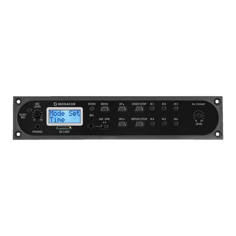
Monacor PA-1120DMT User manual

Monacor

Monacor PA-1120DMT User manual

Monacor MPA-1 User manual

Monacor

Monacor MPA-1 User manual

Monacor img Stage Line DIB-100 User manual

Monacor

Monacor img Stage Line DIB-100 User manual

Monacor PA-1200EX User manual

Monacor

Monacor PA-1200EX User manual

Monacor img Stage Line DMP-30 User manual

Monacor

Monacor img Stage Line DMP-30 User manual

Monacor ATT-442ST User manual

Monacor

Monacor ATT-442ST User manual

Monacor DN-1 User manual

Monacor

Monacor DN-1 User manual

Monacor 0171430 User manual

Monacor

Monacor 0171430 User manual

Monacor ATT-1935 User manual

Monacor

Monacor ATT-1935 User manual

Monacor MPA-1 User manual

Monacor

Monacor MPA-1 User manual

Monacor SAM-200D User manual

Monacor

Monacor SAM-200D User manual

Monacor ATT-506PEU User manual

Monacor

Monacor ATT-506PEU User manual

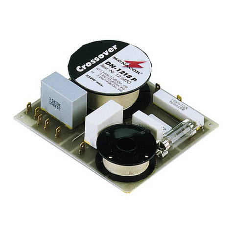
Monacor DN-1218P User manual

Monacor

Monacor DN-1218P User manual

Monacor PA-1200IRD User manual

Monacor

Monacor PA-1200IRD User manual

Monacor PA-24FMM Quick guide

Monacor

Monacor PA-24FMM Quick guide

Monacor TXA-802MBT User manual

Monacor

Monacor TXA-802MBT User manual

Monacor DMP-100R User manual

Monacor

Monacor DMP-100R User manual

Monacor PA-1200C User manual

Monacor

Monacor PA-1200C User manual

Monacor ATT-306PEU User manual

Monacor

Monacor ATT-306PEU User manual

Monacor ATT-135/SI User manual

Monacor

Monacor ATT-135/SI User manual

Monacor TVCCD-38MCOL User manual

Monacor

Monacor TVCCD-38MCOL User manual

Popular Control Unit manuals by other brands

AVer CB-310 user manual

AVer

AVer CB-310 user manual

Wirquin Macdee JOLLYFLUSH Installation

Wirquin

Wirquin Macdee JOLLYFLUSH Installation

Interpump HX operating instructions

Interpump

Interpump HX operating instructions

GEM 514 Assembly instructions

GEM

GEM 514 Assembly instructions

Polycom RMX 1500 Administrator's guide

Polycom

Polycom RMX 1500 Administrator's guide

GET RX1 PRO Guide

GET

GET RX1 PRO Guide

V2 LUX2+ manual

V2

V2 LUX2+ manual

KWC F3SV2001 Installation and operating instructions

KWC

KWC F3SV2001 Installation and operating instructions

Bosch ConnectModule Supplement

Bosch

Bosch ConnectModule Supplement

Rauch QUANTRON-A instruction manual

Rauch

Rauch QUANTRON-A instruction manual

Friendess BCL1501 user manual

Friendess

Friendess BCL1501 user manual

Rockwell Automation Allen-Bradley Micro800 manual

Rockwell Automation

Rockwell Automation Allen-Bradley Micro800 manual

Ebyte E104-BT10-IPX user manual

Ebyte

Ebyte E104-BT10-IPX user manual

Panasonic CF-BAX04GU operating instructions

Panasonic

Panasonic CF-BAX04GU operating instructions

Leadshine Technology DM542 user manual

Leadshine Technology

Leadshine Technology DM542 user manual

LEGRAND BS13 manual

LEGRAND

LEGRAND BS13 manual

Herutu HRF-SG01-US user manual

Herutu

Herutu HRF-SG01-US user manual

CALEFFI 510 Series quick start guide

CALEFFI

CALEFFI 510 Series quick start guide

manuals.online logo
manuals.online logoBrands
  • About & Mission
  • Contact us
  • Privacy Policy
  • Terms and Conditions

Copyright 2025 Manuals.Online. All Rights Reserved.