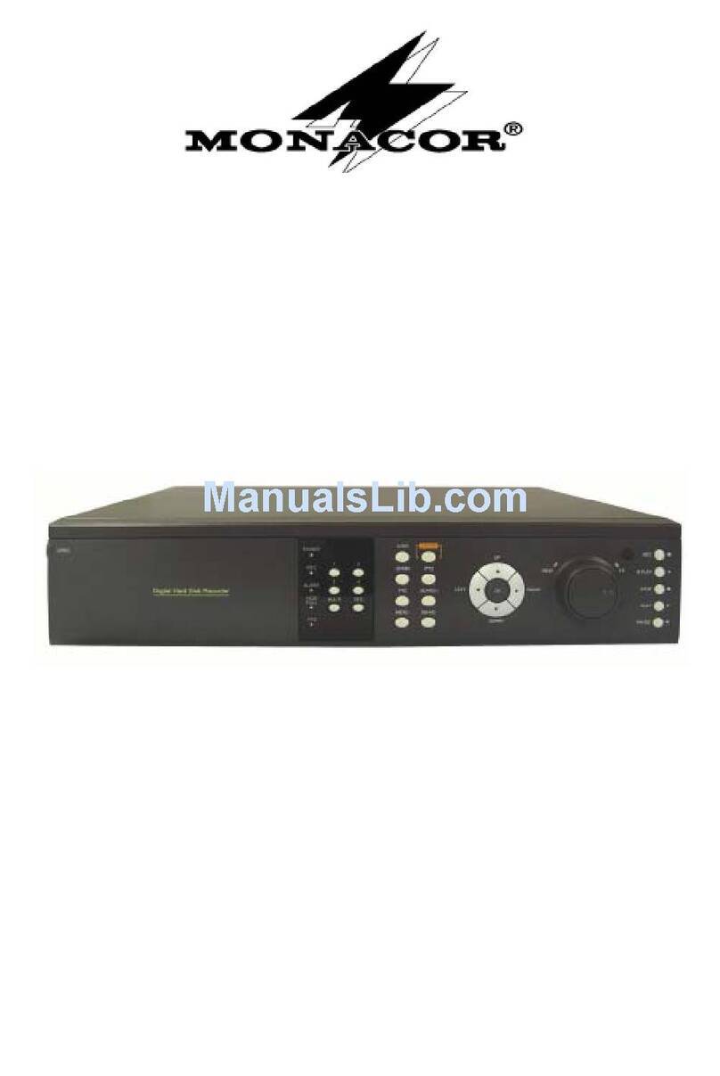
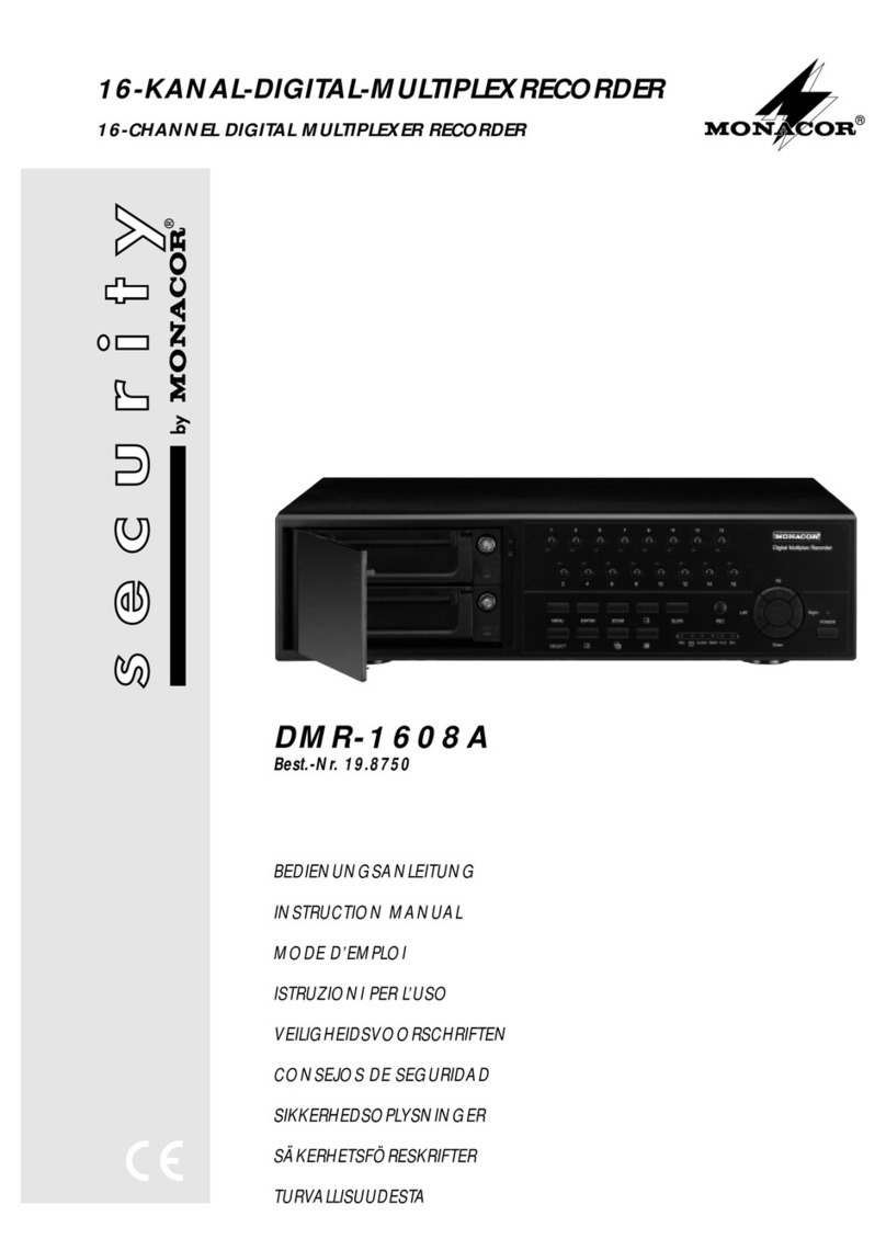
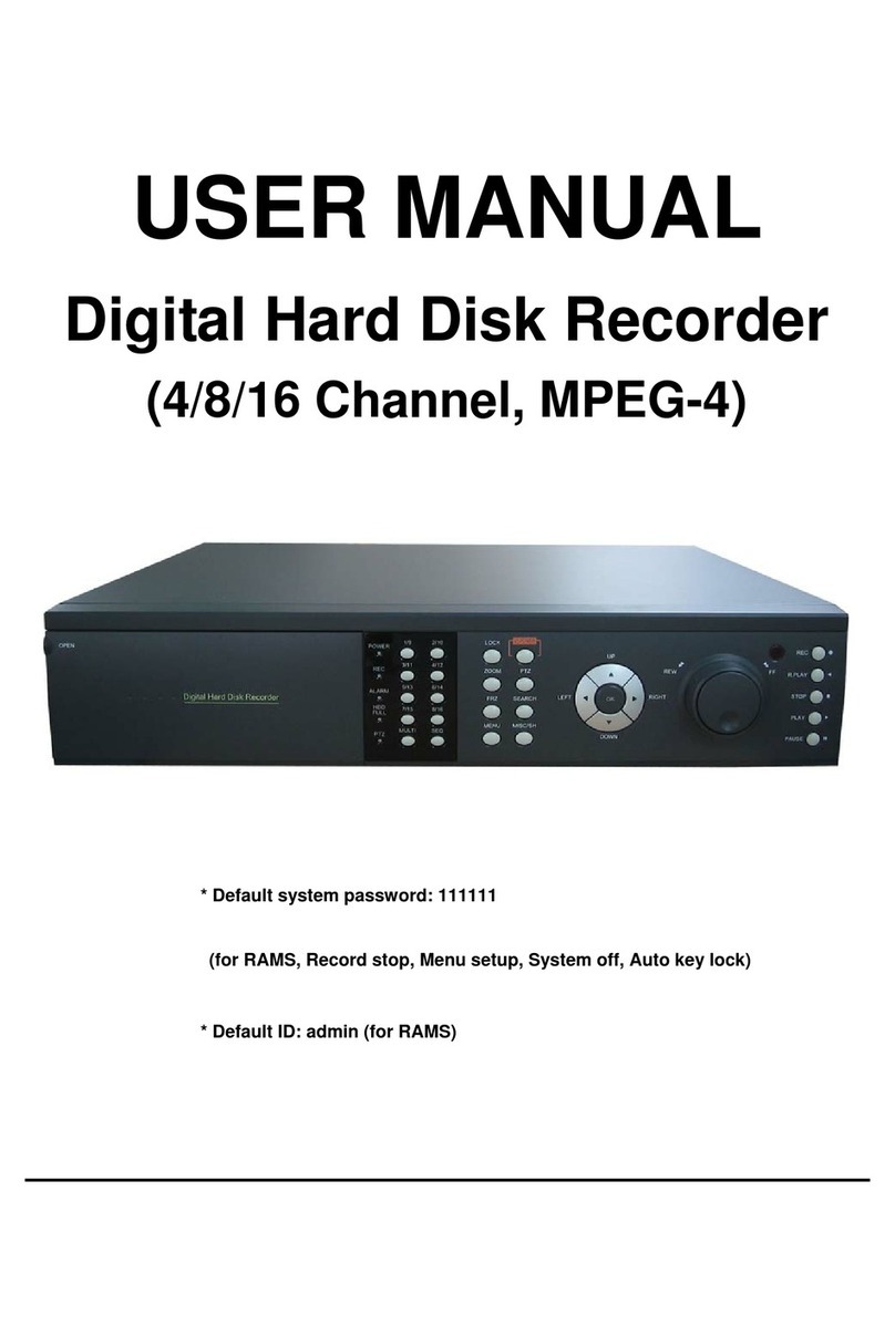
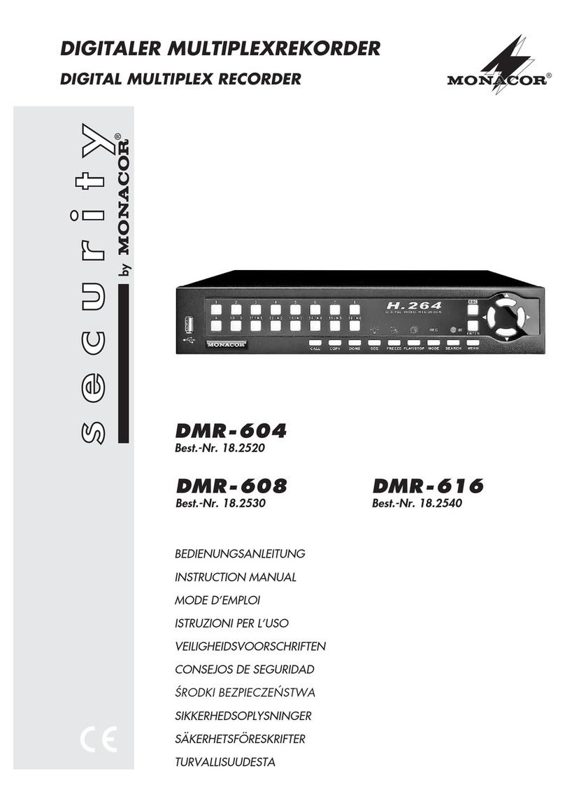
Monacor DVR-108A User manual

BEDIENUNGSANLEITUNG
INSTRUCTION MANUAL
MODE D’EMPLOI
ISTRUZIONI PER L’USO
VEILIGHEIDSVOORSCHRIFTEN
CONSEJOS DE SEGURIDAD
ŚRODKI BEZPIECZEŃSTWA
SIKKERHEDSOPLYSNINGER
SÄKERHETSFÖRESKRIFTER
TURVALLISUUDESTA
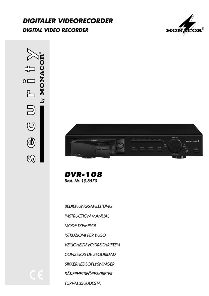
DIGITALER VIDEORECORDER
DIGITAL VIDEO RECORDER
DVR-108A
Best.-Nr. 19.8740
®

2
Bevor Sie einschalten ...
Wir wünschen Ihnen viel Spaß mit Ihrem neuen Gerät
von MONACOR. Dabei soll Ihnen diese Bedienungsan-
leitung helfen alle Funktionsmöglichkeiten kennen zu
lernen. Die Beachtung der Anleitung vermeidet außer-
dem Fehlbedienungen und schützt Sie und Ihr Gerät vor
eventuellen Schäden durch unsachgemäßen Gebrauch.
Den deutschen Text finden Sie auf den Seiten 4–17.
Before you switch on ... ...
We wish you much pleasure with your new unit by
MONACOR. With these operating instructions you will
be able to get to know all functions of the unit. By follow-
ing these instructions false operations will be avoided,
and possible damage to you and your unit due to impro-
per use will be prevented.
You will find the English text on the pages 4–17.
D
A
CH
GB
Avant toute mise en service ...
Nous vous remercions d’avoir choisi un appareil
MONACOR et vous souhaitons beaucoup de plaisir à
l’utiliser. Cette notice a pour objectif de vous aider à
mieux connaître les multiples facettes de l’appareil et à
vous éviter toute mauvaise manipulation.
La version française se trouve pages 18–31.
Prima di accendere ...
Vi auguriamo buon divertimento con il Vostro nuovo ap-
parecchio MONACOR. Le istruzioni per l’uso Vi possono
aiutare a conoscere tutte le possibili funzioni. E
rispettando quanto spiegato nelle istruzioni, evitate di
commettere degli errori, e così proteggete Voi stessi, ma
anche l’apparecchio, da eventuali rischi per uso improprio.
Il testo italiano lo potete trovare alle pagine 18–31.
F
B
CH
I
Voordat u inschakelt ...
Wij wensen u veel plezier met uw nieuw toestel van
MONACOR. Lees de veiligheidsvoorschriften, alvorens
het toestel in gebruik te nemen. Door de veiligheidsvoor-
schriften op te volgen zal een slechte werking vermeden
worden, en zal een eventueel letsel aan uzelf en schade
aan uw toestel tengevolge van onzorgvuldig gebruik
worden voorkomen.
U vindt de veiligheidsvoorschriften op pagina 32.
Antes de cualquier instalación ...
Tenemos de agradecerle el haber adquirido un aparato
MONACOR y le deseamos un agradable uso. Por favor
lee las instrucciones de seguridad antes del uso. La
observación de las instrucciones de seguridad evita ope-
raciones erróneas y protege Vd. y vuestro aparato con-
tra todo daño posible por cualquier uso inadecuado.
Las instrucciones de seguridad se encuentran en la
página 32.
NL
B
E
Przed Uruchomieniem …
Życzymy zadowolenia z nowego produktu MONACOR.
Przed użyciem proszę przeczyta środki bezpieczeń-
stwa. Uniknie się w ten sposób błędów obsługi oraz
uszkodzenia sprzętu w wyniku nieodpowiedniego
użytkowania.
Środki bezpieczeństwa znajdują się na stronie 32.
Inden De tænder for apparatet ...
Vi ønsker Dem god fornøjelse med Deres nye MONA-
COR apparat. Læs oplysningerne for en sikker brug af
apparatet før ibrugtagning. Følg sikkerhedsoplysnin-
gerne for at undgå forkert betjening og for at beskytte
Dem og Deres apparat mod skade på grund af forkert
brug.
Sikkerhedsoplysningerne finder De på side 33.
PL DK
Förskrift
Vi önskar dig mycket nöje med din nya enhet från
MONACOR. Läs gärna säkerhetsinstruktionerna innan
du använder enheten. Genom att följa säkerhetsinstruk-
tionerna kan många problem undvikas, vilket annars kan
skada enheten.
Du finner säkerhetsinstruktionerna på sidan 33.
SEnnen virran kytkemistä…
Toivomme, että uusi MONACOR-laitteesi tuo sinulle pal-
jon iloa ja hyötyä. Ole hyvä ja lue käyttöohjeet ennen lait-
teen käyttöönottoa. Luettuasi käyttöohjeet voit käyttää
laitetta turvallisesti ja vältyt laitteen väärinkäytöltä.
Käyttöohjeet löydät sivulta 33.
FIN

. . . .
EXTERNAL I/O
POWER
VIDEO OUT
VIDEO IN AUDIO
INOUT
L
R
CAM 2 CAM 3 CAM 4 CAM 5 CAM6 CAM 7 CAM 8 CAM 9 CAM 10 CAM 11 CAM12 CAM 13 CAM14 CAM 15
IN
OUT
REMOTE
POWER
ALARM DC 12V
CAM 16CAM 1 MAIN
SPOT
VCR
Camera 1
VIDEO Camera 16
VIDEO
CCD CAMERA
VIDEO VIDEO
POWER
H-HOLD V-HOLD BRIGHT CONTRAST
Second Monitor Computer
REMOTE CONTROL
VIDEO
Alarm
Sensor 1 Alarm
Sensor 16
. . . .
ALARM IN
Multiplexer
Alarm Device
ALARM OUT
AUDIO
VIDEO ALARM OUT
AUDIO
CCD CAMERA
POWER
H-HOLD V-HOLD BRIGHT CONTRAST
Main Monitor
EXTERNAL I/O
POWER
VIDEO OUT
VIDEO IN AUDIO
INOUT
L
R
VIDEO AUDIO
Camera
CCD CAMERA
ALARM IN
Computer
Alarm Sensor
REMOTE CONTROL
Alarm Device
ALARM OUT
AUDIO
POWER
H-HOLD V-HOLD BRIGHT CONTRAST
Monitor
VIDEO
3
ALARM TIMER PLAY RECHDD FullHDD
MENU ENTER SEARCH SLOW
POWER
PAUSE/ Up
STOP/ Down
FF
Right
REW
Left
REC
®
Digital Video Recorder
EXTERNAL I/O
POWER
VIDEO OUT
VIDEO IN AUDIO
INOUT
L
R
16 17 18 19 20 21
12345
6 7 8 9 10 11 12 13 14 15
RS-232: RX
RS-232: TX
Video Loss
Switch Out
Error Out
Rec Start
Alarm Relay: NC
Alarm Relay: NO
1
9
8
15
Ground
RS-485: B
RS-485: A
Disk Full
Alarm Reset
Alarm Input
Alarm Relay: COM
1
2
34
5

Bitte klappen Sie die Seite 3 heraus. Sie sehen
dann immer die beschriebenen Bedienelemente
und Anschlüsse.
Inhalt
1 Übersicht der Bedienelemente und
Anschlüsse . . . . . . . . . . . . . . . . . . . . . . . . 4
1.1 Frontseite . . . . . . . . . . . . . . . . . . . . . . . . . . 4
1.2 Rückseite . . . . . . . . . . . . . . . . . . . . . . . . . . 5
2 Hinweise für den sicheren Gebrauch . . . 5
3 Anwendungsmöglichkeiten . . . . . . . . . . . 6
4 Aufstellung/Rack-Montage . . . . . . . . . . . 6
5 Geräte anschließen . . . . . . . . . . . . . . . . . . 6
5.1 Videoein- und -ausgang . . . . . . . . . . . . . . . 6
5.2 Audioein- und -ausgang . . . . . . . . . . . . . . . 6
5.3 Alarm- und Steueranschlüsse . . . . . . . . . . . 6
5.4 Anschluss eines Computers/Terminals . . . 7
6 Inbetriebnahme . . . . . . . . . . . . . . . . . . . . . 8
6.1 Bedientasten sperren . . . . . . . . . . . . . . . . . 8
6.2 Bildverlust-Erkennung . . . . . . . . . . . . . . . . . 8
7 Aufnahme . . . . . . . . . . . . . . . . . . . . . . . . . . 8
7.1 Manuelle Aufnahme . . . . . . . . . . . . . . . . . . 8
7.2 Timergesteuerte Aufnahme . . . . . . . . . . . . . 9
7.3 Aufnahme bei externem Triggersignal . . . . 9
7.4 Alarmaufnahme . . . . . . . . . . . . . . . . . . . . . . 9
8 Wiedergabe . . . . . . . . . . . . . . . . . . . . . . . . 9
8.1 Normale Wiedergabe . . . . . . . . . . . . . . . . . 9
8.1.1 Schneller Vor-/Rücklauf . . . . . . . . . . . . . . 9
8.1.2 Langsamer Vor-/Rücklauf . . . . . . . . . . . . 9
8.1.3 Schrittweise Wiedergabe von
Einzelbildern im Pausenmodus . . . . . . . 10
8.2 Aufnahme-Suchfunktion . . . . . . . . . . . . . . 10
8.2.1 „Last Record“: Wiedergabe der letzten
Aufnahme . . . . . . . . . . . . . . . . . . . . . . . . 10
8.2.2 „Full List“: Gesamtliste aller Aufnahmen . 10
8.2.3 „Alarm List“: Liste aller Alarmaufnahmen 10
8.2.4 „Time Search“: Aufnahmesuche über
Zeit-/Datumsangabe . . . . . . . . . . . . . . . . 11
9 Änderung der Recorder-Einstellungen
über das Bildschirm-Menü . . . . . . . . . . . 11
9.1 Hauptmenü . . . . . . . . . . . . . . . . . . . . . . . . 11
9.1.1 Untermenü „Timer“ . . . . . . . . . . . . . . . . . 12
9.1.2 Untermenü „Record“ . . . . . . . . . . . . . . . . 12
9.1.3 Untermenü „Alarm“ . . . . . . . . . . . . . . . . . 13
9.1.4 Untermenü „Remote“ . . . . . . . . . . . . . . . 13
9.1.5 Untermenü „System“ . . . . . . . . . . . . . . . 14
9.1.6 Untermenü „Event“ . . . . . . . . . . . . . . . . 15
10 Befehlsübersicht für die
Computer-Schnittstelle . . . . . . . . . . . . . . 15
11 Festplatte auswechseln . . . . . . . . . . . . . 16
11.1 Festplatteneinschub herausnehmen . . . . . 16
11.2 Neue Festplatte einsetzen . . . . . . . . . . . . 16
12 Technische Daten . . . . . . . . . . . . . . . . . . 17
Anhang A: Aufnahmezeiten: . . . . . . . . . . . 17
Anhang B: Kompatible Festplatten: . . . . . . 17
1 Übersicht der Bedienelemente und
Anschlüsse
1.1 Frontseite (Abb. 1)
1LED-Statusanzeigen
„HDD“: leuchtet bei Zugriff auf die Fest-
platte
„HDD Full“: leuchtet, wenn die Speicherkapazi-
tät der Festplatte erschöpft ist
„ALARM“: leuchtet bei eingeschalteter Alarm-
funktion [siehe im Menü „Alarm“
(Kap. 9.1.3) die Einstellung „Alarm
Enable“];
blinkt nachAuslösung einesAlarms
„TIMER“: leuchtet bei eingeschalteter Timer-
Funktion [siehe im Menü „Timer“
(Kap. 9.1.1) die Einstellung „Timer
Enable“]
„PLAY“: leuchtet während der Wiedergabe
„REC“: leuchtet während der Aufnahme
2Taste „REW/Left“: dient
afür den schnellen und langsamen Bild-Rück-
lauf im Wiedergabebetrieb
bals Cursor-Taste „Links“ für Einstellungen im
Bildschirm-Menü
3Taste „PAUSE/Up“: dient
aals Pausentaste im Wiedergabebetrieb
bals Cursor-Taste „Aufwärts“ für Einstellungen
im Bildschirm-Menü
4Starttaste zum Starten der Wiedergabe
5Taste „FF/Right“: dient
afür den schnellen und langsamen Bild-Vorlauf
im Wiedergabebetrieb
bals Cursor-Taste „Rechts“ für Einstellungen im
Bildschirm-Menü
6auswechselbarer Festplatteneinschub
ZumHerausnehmen des Einschubs muss dieser
über das Schloss (8) entriegelt werden (siehe
Abb. 6 in Kap. 11.1).
Please unfold page 3. Then you can always see
the operating elements and connections de-
scribed.
Contents
1 Operating Elements and Connections . . 4
1.1 Front panel . . . . . . . . . . . . . . . . . . . . . . . . . 4
1.2 Rear panel . . . . . . . . . . . . . . . . . . . . . . . . . . 5
2 Safety Notes . . . . . . . . . . . . . . . . . . . . . . . 5
3 Applications . . . . . . . . . . . . . . . . . . . . . . . . 6
4 Setting Up/Rack Installation . . . . . . . . . . 6
5 Connection of Units . . . . . . . . . . . . . . . . . 6
5.1 Video input and video output . . . . . . . . . . . . 6
5.2 Audio input and audio output . . . . . . . . . . . 6
5.3 Alarm and control connections . . . . . . . . . . 7
5.4 Connection of a computer/terminal . . . . . . . 7
6 Operation . . . . . . . . . . . . . . . . . . . . . . . . . . 8
6.1 Locking of control keys . . . . . . . . . . . . . . . . 8
6.2 Video loss recognition . . . . . . . . . . . . . . . . . 8
7 Recording . . . . . . . . . . . . . . . . . . . . . . . . . 8
7.1 Manual recording . . . . . . . . . . . . . . . . . . . . 8
7.2 Timer controlled recording . . . . . . . . . . . . . . 8
7.3 Recording via external trigger signal . . . . . . 9
7.4 Alarm recording . . . . . . . . . . . . . . . . . . . . . . 9
8 Replay . . . . . . . . . . . . . . . . . . . . . . . . . . . . 9
8.1 Normal replay . . . . . . . . . . . . . . . . . . . . . . . 9
8.1.1 Fast forward/rewind . . . . . . . . . . . . . . . . . 9
8.1.2 Slow forward/rewind . . . . . . . . . . . . . . . . . 9
8.1.3 Step-by-step replay of individual
pictures in the pause mode . . . . . . . . . . . 9
8.2 Search function for a recording . . . . . . . . . 10
8.2.1 “Last Record”: replay of
the last recording . . . . . . . . . . . . . . . . . . 10
8.2.2 “Full List”: list of all recordings . . . . . . . . 10
8.2.3 “Alarm List”: list of all alarm recordings . 10
8.2.4 “Time Search”: search for a recording
via time/date indication . . . . . . . . . . . . 10
9 Modification of recorder settings
via OSD menu . . . . . . . . . . . . . . . . . . . . . 11
9.1 Main menu . . . . . . . . . . . . . . . . . . . . . . . . . 11
9.1.1 Submenu “Timer” . . . . . . . . . . . . . . . . . . 11
9.1.2 Submenu “Record” . . . . . . . . . . . . . . . . . 12
9.1.3 Submenu “Alarm” . . . . . . . . . . . . . . . . . . 12
9.1.4 Submenu “Remote” . . . . . . . . . . . . . . . . 13
9.1.5 Submenu “System” . . . . . . . . . . . . . . . . . 13
9.1.6 Submenu “Event” . . . . . . . . . . . . . . . . . . 14
10 List of Commands for
the Computer Interface . . . . . . . . . . . . . . 15
11 Replacement of the Hard Disk . . . . . . . . 16
11.1 Removing the hard disk insertion . . . . . . . 16
11.2 Inserting a new hard disk . . . . . . . . . . . . . 16
12 Specifications . . . . . . . . . . . . . . . . . . . . . 17
Annex A: Recording times . . . . . . . . . . . . . 17
Annex B: Compatible hard disks . . . . . . . . 17
1 Operating Elements and Connections
1.1 Front panel (fig. 1)
1LED status indications
“HDD”: lights up during access to the hard
disk
“HDD Full”: lights up when the storage capacity
of the hard disk is exhausted
“ALARM”: lights up with activated alarm func-
tion [see menu “Alarm” (chapter
9.1.3), setting “Alarm Enable”];
flashes when an alarm has been
triggered
“TIMER”: lights up with activated timer func-
tion [see menu “Timer” (chapter
9.1.1), setting “Timer Enable”]
“PLAY”: lights up during replay
“REC”: lights up during recording
2Button “REW/Left”: serves
afor fast and slow picture rewind in replay mode
bas cursor key “Left” for settings in the OSD
menu
3Button “PAUSE/Up”: serves
aas pause button in the replay mode
bas cursor key “Up” for settings in the OSD
menu
4Start button for starting the replay
5Button “FF/Right”: serves
afor fast and slow forward of the picture in the
replay mode
bas cursor key “Right” for settings in the OSD
menu
6Replaceable hard disk insertion
To remove the insertion, unlock it via the lock (8)
[see fig. 6 in chapter 11.1].
7Indicating LEDs for the hard disk insertion:
yellow LED: lights up during access to the
hard disk
4
GB
D
A
CH

7Kontroll-Anzeigen für den Festplatteneinschub:
gelbe LED: leuchtet bei Zugriff auf die Fest-
platte
grüne LED: Betriebsanzeige; leuchtet bei
Stromversorgung der Festplatte
8Schloss zum Verriegeln/Entriegeln des Festpla-
teneinschubs (6) mit den zwei beiliegenden
Schlüsseln, siehe auch Abb. 6 in Kap. 11.1
9Taste „MENU“ zum Aufrufen des Bildschirm-
Menüs; nach dem Drücken der Taste wird das
4-stellige Passwort abgefragt:
Wurde das ab Werk voreingestellte Passwort
„0000“ beibehalten, zur Bestätigung die Taste
„ENTER“ (10) drücken.
Wurde ein neues Passwort eingestellt (siehe
Kap. 9.1.5), mit der Cursor-Taste „Left“ (2)
oder „Right“ (5) die vier Stellen anwählen und
mit der Cursor-Taste „Up“ (3) oder „Down“ (13)
die jeweiligen Zahlen einstellen. Die Eingabe
mit der Taste „ENTER“ (10) bestätigen.
10 Taste „ENTER“ zum Bestätigen der Einstellun-
gen im Bildschirm-Menü
11 Taste „SEARCH“ zum Aufrufen des Suchmenüs
für die gezielte Suche einer Aufnahme
12 Taste „SLOW“ zum Reduzieren der Wiedergabe-
geschwindigkeit
13 Taste „STOP/Down“: dient
aals Stopptaste während der Aufnahme und
der Wiedergabe
bals Cursor-Taste „Abwärts“ für Einstellungen
im Bildschirm-Menü
14 Taste „REC“ zum manuellen Starten der Auf-
nahme
15 Ein-/Ausschalter „POWER“; mit Kontroll-LED zur
Anzeige des Betriebszustands:
rot: Standby-Betrieb; der Recorder ist an die
Stromversorgung angeschlossen, aber
noch ausgeschaltet
orange: während der Initialisierung des Recor-
ders nach dem Einschalten
grün: der Recorder ist eingeschaltet und be-
triebsbereit
1.2 Rückseite (Abb. 2)
16 Videoeingang (BNC-Buchse) zum Anschluss an
den Videoausgang der Kamera bzw. an den für
die Aufnahme vorgesehenen Videoausgang am
Multiplexer oder Video-Splitter
17 Mini-DIN-Buchse „POWER“ für den Anschluss
des beiliegenden Netzgerätes
18 Videoausgang (BNC-Buchse) zumAnschluss an
den Videoeingang des Monitors bzw. beim Multi-
plexer oder Video-Splitter an den Videoeingang,
der für die Videorecorder-Wiedergabe vorgese-
hen ist
19 Stereo-Audioausgang (Cinch-Buchsen) zum An-
schluss an den Audioeingang des verwendeten
Monitors oder an einen Line-Pegel-Eingang einer
Audioanlage
20 Stereo-Audioeingang (Cinch-Buchsen) zum An-
schluss an den Audioausgang einer Kamera
oder einer anderen Audioquelle (z.B. Mikrofon-
vorverstärker eines separat aufgestellten Mikro-
fons)
21 15-polige Sub-D-Buchse „EXTERNAL I/O“ (sie-
he Abb. 5) für verschiedene Alarm- und Steuer-
verbindungen; Details siehe Kap. 5.3 und 5.4
Pin 1: RS-232-Schnittstelle: RX
Pin 2: RS-232-Schnittstelle: TX
Pin 3: Ausgang „Video Loss“; meldet Signal-
verlust am Videoeingang (16)
Pin 4: Ausgang „Switch Out“ zur Synchronisa-
tion eines angeschlossenen Multiplexers
Pin 5: Ausgang „Error Out“; meldet fehlerhafte
Operationen der Festplatte
Pin 6: Steuereingang „Rec Start“ zum Starten/
Stoppen der Aufnahme über ein exter-
nes Triggersignal
Pin 7: Alarmausgang: NC-Kontakt („normally
closed“) des Relais
Pin 8: Alarmausgang: NO-Kontakt („normally
open“) des Relais
Pin 9: Masse
Pin 10: RS-485-Schnittstelle: B
Pin 11: RS-485-Schnittstelle: A
Pin 12: Steuerausgang „Disk Full“ zum Starten
eines zweiten Digitalrecorders, wenn
die Speicherkapazität der Festplatte
erschöpft ist
Pin 13: „Alarm Reset“-Eingang zur Alarmzu-
rücksetzung
Pin 14: Alarm-Eingang, um das Gerät in den
Alarmmodus zu schalten
Pin 15: Alarmausgang: gemeinsamerAnschluss
(COM) des Relais
2 Hinweise für den sicheren Gebrauch
Der Recorder und sein Netzgerät entsprechen der
EMV-Richtlinie für elektromagnetische Verträglich-
keit 89/336/EWG. Das Netzgerät entspricht zusätz-
lich der Niederspannungsrichtlinie 73/23/EWG.
Beachten Sie auch unbedingt folgende Punkte:
●Der Recorder und das Netzgerät sind nur zur Ver-
wendung im Innenbereich geeignet. Schützen Sie
die Geräte vor Tropf- und Spritzwasser, hoher
Luftfeuchtigkeit und Hitze (zulässiger Einsatztem-
peraturbereich 10–40°C).
●Stellen Sie keine mit Flüssigkeit gefüllten Gefäße,
z.B. Trinkgläser oder Vasen, auf die Geräte.
●Die im Recorder entstehende Wärme muss durch
Luftzirkulation abgegeben werden. Darum dürfen
Achtung! Das Netzgerät wird mit lebensgefährli-
cher Netzspannung versorgt. Nehmen Sie deshalb
nie selbst Eingriffe in diesem Gerät vor. Durch
unsachgemäßes Vorgehen besteht die Gefahr
eines elektrischen Schlages. Außerdem erlischt
beim Öffnen des Netzgeräts oder des Recorders
jeglicher Garantieanspruch.
green LED: power LED; lights up during
power supply of the hard disk
8Lock for locking/unlocking the hard disk insertion
(6) with the two supplied keys, also see fig. 6 in
chapter 11.1
9Key “MENU” for calling the OSD menu; after
pressing the key, the 4-digit password is re-
quested:
If the factory-set password “0000” was main-
tained, press the key “ENTER” (10) to confirm.
If a new password was entered (see chapter
9.1.5), use the cursor key “Left” (2) or “Right”
(5) to select the four digits and use the cursor
key “Up” (3) or “Down” (13) to set the respec-
tive numbers. Press the key “ENTER” (10) to
confirm.
10 Key “ENTER” for confirming the settings in the
OSD menu
11 Key “SEARCH” for calling the search menu for
the purposeful search for a recording
12 Key “SLOW” for reducing the replay speed
13 Key “STOP/Down”: serves
aas stop key during recording and replay
bas cursor key “Down” for settings in the OSD
menu
14 Key “REC” for manual start of the recording
15 “POWER” switch; with LED for indicating the
operating mode:
red: stand-by mode; the recorder is
connected to the power supply
but is still switched off
orange: during initialization of the record-
er after switching on
green: the recorder is switched on and
ready for operation
1.2 Rear panel (fig. 2)
16 Video input (BNC jack) for connecting the video
output of the camera or the video output pro-
vided for recording on the multiplexer or video
splitter
17 Mini-DIN jack “POWER” for connecting the sup-
plied power supply unit
18 Video output (BNC jack) for connecting the video
input of the monitor or the video input on the mul-
tiplexer or video splitter provided for video re-
corder replay
19 Stereo audio output (phono jacks) for connecting
the audio input of the monitor used or a line level
input of an audio system
20 Stereo audio input (phono jacks) for connecting
the audio output of a camera or another audio
source (e.g. microphone preamplifier of a micro-
phone placed separately)
21 15-pole Sub-D jack “EXTERNAL I/O” (see fig. 5)
for various alarm and control connections;
details see chapters 5.3 and 5.4
pin 1: RS-232 interface: RX
pin 2: RS-232 interface: TX
pin 3: output “Video Loss”, indicates signal
loss at the video input (16)
pin 4: output “Switch Out” for synchronizing a
connected multiplexer
pin 5: output “Error Out”; indicates faulty oper-
ation of the hard disk
pin 6: control input “Rec Start” for starting/
stopping the recording via an external
trigger signal
pin 7: alarm output: NC (normally closed)
contact of the relay
pin 8: alarm output: NO (normally open)
contact of the relay
pin 9: ground
pin 10: RS-485 interface: B
pin 11: RS-485 interface: A
pin 12: control output “Disk Full” for starting a
second digital recorder if the storage
capacity of the hard disk is exhausted
pin 13: “Alarm Reset” input for alarm reset
pin 14: alarm input for switching the unit to the
alarm mode
pin 15: alarm output: common connection
(COM) of the relay
2 Safety Notes
The recorder and its power supply unit correspond
to the directive for electromagnetic compatibility
89/336/EEC. The power supply unit also corre-
sponds to the low voltage directive 73/23/EEC.
Please observe the following items in any case:
●The recorder and the power supply unit are suita-
ble for indoor use only. Protect them against drip-
ping water and splash water, high air humidity,
and heat (admissible ambient temperature range
10–40°C).
●Do not place any vessel filled with liquid on the
units, e.g. a drinking glass or a vase.
●The heat generated in the recorder must be
carried off by air circulation; never cover the air
vents of the housing (e.g. by curtains).
●Never insert anything into the air vents! This may
result in a defect of the unit.
●Do not operate the recorder or immediately dis-
connect the mains plug of the power supply unit
from the mains socket
1. if there is visible damage to the power supply
unit, to its mains cable or to the recorder,
2. if a defect might have occurred after a unit was
dropped or suffered a similar accident,
3. if malfunctions occur.
In any case the units must be repaired by skilled
personnel.
Attention! The power supply unit is supplied with
hazardous mains voltage. Leave servicing to
skilled personnel only. Inexpert handling may
cause an electric shock hazard. Furthermore, any
guarantee claim will expire if the power supply unit
or the recorder has been opened.
5
GB
D
A
CH

die Lüftungsschlitze an den Gehäusen nicht abge-
deckt werden (z.B. durch Vorhänge).
●Stecken Sie nichts durch die Lüftungsschlitze!
Dies kann zu einem Defekt des Gerätes führen.
●Nehmen Sie den Recorder nicht in Betrieb bzw.
ziehen Sie den Netzstecker des Netzgerätes
sofort aus der Steckdose, wenn:
1. sichtbare Schäden am Netzgerät, an dessen
Netzleitung oder am Recorder vorhanden sind,
2. nach einem Sturz oder Ähnlichem der Verdacht
auf einen Defekt besteht,
3. Funktionsstörungen auftreten.
Lassen Sie die Geräte in jedem Fall in einer Fach-
werkstatt reparieren.
●Ziehen Sie den Netzstecker des Netzgerätes nie
an der Zuleitung aus der Steckdose, fassen Sie
immer am Stecker an.
●Verwenden Sie zum Reinigen nur ein trockenes
weiches Tuch, niemals Chemikalien oder Wasser.
●Werden der Recorder oder das Netzgerät zweck-
entfremdet, falsch angeschlossen bzw. bedient
oder nicht fachgerecht repariert, kann keine Haf-
tung für daraus resultierende Sach- oder Perso-
nenschäden und keine Garantie für das Gerät
übernommen werden.
3 Anwendungsmöglichkeiten
Der digitale 1-Kanal-Farb-Videorecorder DVR-108A
ist speziell für den Einsatz in CCTV-Anlagen konzi-
piert. Er ist kompatibel zu den meisten Multiplexern
und Quad-Prozessoren.
Der Digitalrecorder kann in einem Überwachungs-
system anstelle eines analogen Langzeitrecorders
verwendet werden. Die analogen Bilder der Video-
quellen werden digitalisiert, komprimiert und auf der
Festplatte gesichert. Zu jeder Aufnahme werden
Angaben bezüglich Datum, Zeit und Aufnahmemo-
dus abgespeichert. Für die Wiedergabe werden die
Bilder von der Festplatte heruntergeladen, dekompri-
miert, in analoge Videosignale umgewandelt und auf
den Ausgang gegeben.
Das Gerät bietet folgende Funktionen:
– 7 Aufnahmegeschwindigkeiten (max. 50 Bilder
pro Sekunde, min. 1 Bild pro Sekunde)
– 4Aufnahmequalitäten (Best, High, Normal, Basic)
– 4 Aufnahmemodi (manuelle Aufzeichnung, timer-
gesteuerte Aufzeichnung, durch ein Alarmsignal
ausgelöste Aufzeichnung, durch ein Triggersig-
nal ausgelöste Aufzeichnung)
– Audioaufzeichnung
– Aufnahmesuche über Zeit-/Datumsangabe
– schneller und langsamer Vor-/Rücklauf mit
jeweils 5 wählbaren Geschwindigkeiten
– Passwortschutz
– Ereignisse während derAufnahme, wie z.B. Bild-
verlust oder Stromunterbrechung, werden in
einer Ereignisliste aufgeführt
– Ein- und Ausgänge zur Alarmauswertung
– RS-232- und RS-485-Schnittstelle zur Steuerung
des Gerätes über Computer oder Terminal
4 Aufstellung/Rack-Montage
Der Digitalrecorder ist als frei aufstellbares Tisch-
gerät ausgelegt.
Montagewinkel zum Einbau des Gerätes in ein
Rack (482mm/19") können bei Bedarf über den
Ersatzteildienst von MONACOR INTERNATIONAL
in Bremen, Deutschland, angefordert werden. Wen-
den Sie sich in diesem Fall an Ihren MONACOR-
Fachhändler.
5 Geräte anschließen
Vor dem Anschließen von Geräten bzw. vor dem
Ändern bestehender Anschlüsse den Digitalrecor-
der ausschalten.
Die Abbildungen 3 und 4 auf Seite 3 zeigen mögli-
che Anschlüsse für zwei Anwendungsbeispiele.
Abb. 3: Anschlussdiagramm bei Verwendung einer
einzelnen Kamera
Abb. 4: Anschlussdiagramm bei Verwendung eines
Multiplexers
5.1 Videoein- und -ausgang
An die BNC-Buchse „VIDEO IN“ (16) den Videoaus-
gang der Kamera bzw. bei Verwendung eines Multi-
plexers oder Quad-Prozessors den für die Video-
recorder-Aufnahme vorgesehenen Ausgang (mögli-
che Beschriftung „VCR OUT“ bzw. „QUAD OUT“)
anschließen.
An die BNC-Buchse „VIDEO OUT“ (18) den
Videoeingang des Monitors bzw. bei Verwendung
eines Multiplexers oder Quad-Prozessors den für die
Videorecorder-Wiedergabe vorgesehenen Videoein-
gang (mögliche Beschriftung „VCR IN“) anschließen.
5.2 Audioein- und -ausgang
Zur Tonaufzeichnung und -wiedergabe verfügt der
Recorder über einen Stereo-Audioeingang „AUDIO
IN“ (20) und einen Stereo-Audioausgang „AUDIO
OUT“ (19): weiße Cinch-Buchse „L“ = linker Kanal,
rote Cinch-Buchse „R“ = rechter Kanal.
An den Audioeingang kann z.B. der Audioaus-
gang einer Kamera mit integriertem Mikrofon ange-
schlossen werden oder der Vorverstärker eines se-
parat aufgestellten Mikrofons.
Über einen Monitor mit integriertem Lautsprecher
kann die Tonaufzeichnung wiedergegeben werden.
Den Audioausgang mit dem Audioeingang des Mo-
nitors verbinden. Soll der Ton über eineAudioanlage
wiedergegeben werden, denAudioausgang an einen
Line-Eingang der Anlage anschließen.
5.3 Alarm- und Steueranschlüsse
Über die 15-polige Sub-D-Buchse „EXTERNAL I/O“
(21) [siehe Abb. 5] bietet der Digitalrecorder ver-
schiedene Ein- und Ausgänge zur Steuerung und
Sollen die Geräte endgültig aus dem
Betrieb genommen werden, übergeben
Sie sie zur umweltgerechten Entsorgung
einem örtlichen Recyclingbetrieb.
●Never pull the mains cable when disconnecting
the mains plug of the power supply unit from the
socket, always seize the plug.
●For cleaning only use a dry, soft cloth; never use
chemicals or water.
●No guarantee claims for the unit or liability for any
resulting personal damage or material damage
will be accepted if the recorder or the power sup-
ply unit is used for other purposes than originally
intended, if it is not correctly connected, operated
or not repaired in an expert way.
●Important for U.K. Customers!
The wires in the mains lead of the power supply unit
are coloured in accordance with the following code:
green/yellow = earth
blue = neutral
brown = live
As the colours of the wires in the mains lead of this
appliance may not correspond with the coloured
markings identifying the terminals in your plug,
proceed as follows:
1. The wire which is coloured green and yellow
must be connected to the terminal in the plug
which is marked with the letter Eor by the earth
symbol , or coloured green or green and
yellow.
2. The wire which is coloured blue must be con-
nected to the terminal which is marked with the
letter Nor coloured black.
3. The wire which is coloured brown must be con-
nected to the terminal which is marked with the
letter Lor coloured red.
Warning
-
This appliance must be earthed.
3 Applications
The digital 1-channel colour video recorder DVR-
108A is specially designed for application in CCTV
systems. It is compatible with most multiplexers and
quad processors.
The digital recorder can be used in a surveillance
system instead of an analog time-lapse recorder. The
analog pictures of the video sources are digitized,
compressed, and stored on the hard disk. For each
recording, data concerning date, time, and recording
mode are stored. For replay, the pictures are down-
loaded from the hard disk, decompressed, converted
into analog video signals, and fed to the output.
The unit offers the following features:
– 7 recording speeds (max. 50 images per second,
min. 1 image per second)
– 4 recording qualities (Best, High, Normal, Basic)
– 4 recording modes (manual recording, timer con-
trolled recording, recording triggered via an alarm
signal, recording triggered via a trigger signal)
– audio recording
– search for a recording via time/date indication
– fast and slow forward/rewind each with 5 availa-
ble speeds
– password protection
– events occurred during recording, e.g. video loss
or power failure, are listed in an event list
– inputs and outputs for alarm evaluation
– RS-232 and RS-485 interfaces for control of the
unit via computer or terminal
4 Setting Up/Rack Installation
The digital recorder is designed as a free-standing
table-top unit.
If required, mounting brackets for installing the
unit into a rack (482mm/19") can be ordered via the
MONACOR INTERNATIONAL spare parts service
in Bremen, Germany. In this case, please contact
your MONACOR retailer.
5 Connection of Units
Prior to connecting any units or to changing any ex-
isting connections, switch off the digital recorder.
Figures 3 and 4 on page 3 show possible connec-
tions for two examples for application.
Fig. 3: Connection diagram when using a single
camera
Fig. 4: Connection diagram when using a multi-
plexer
5.1 Video input and video output
At the BNC jack “VIDEO IN” (16), connect the video
output of the camera or when using a multiplexer or
quad processor, connect the output provided for
recording via video recorder (possible marking
“VCR OUT” or “QUAD OUT”).
At the BNC jack “VIDEO OUT” (18), connect the
video input of the monitor or when using a multi-
plexer or quad processor, connect the video input
provided for replay via video recorder (possible
marking “VCR IN”).
5.2 Audio input and audio output
For audio recording and replay, the recorder is
equipped with a stereo audio input “AUDIO IN” (20)
and a stereo audio output “AUDIO OUT” (19): white
phono jack “L” = left channel, red phono jack “R” =
right channel.
The audio input allows e.g. connection of the
audio output of a camera with integrated micro-
phone or connection of the preamplifier of a micro-
phone placed separately.
The audio recording can be replayed via a moni-
tor with integrated speaker. Connect the audio out-
put to the audio input of the monitor. For replaying
the sound via an audio system, connect the audio
output to a line input of the system.
If the recorder and the power supply unit
are to be put out of operation definitively,
take them to a local recycling plant for a
disposal which is not harmful to the envi-
ronment.
6
GB
D
A
CH

Alarmauswertung. Für den Anschluss liegt dem
Recorder ein 15-poliger Stecker bei.
– Ausgang „Video Loss“ (Pin 3) zur Meldung
von Bildverlust
Bei Bildverlust am Videoeingang (16) schaltet der
Ausgang von High-Pegel (5V) auf Low-Pegel (0V)
um und kann damit ein hier angeschlossenes Gerät
aktivieren.
– Synchronisationsausgang „Switch Out“ (Pin 4)
Um die Bildumschaltung eines angeschlossenen
Mulitplexers mit den Aufnahmeintervallen des
Recorders zu synchronisieren, liefert dieser Aus-
gang ein Synchronisationssignal. Den Ausgang mit
dem Synchronisationseingang am Multiplexer ver-
binden. Das Synchronisationssignal hat negative
Polarität (Synchronimpuls = 0V).
– Fehlermeldeausgang „Error Out“ (Pin 5)
Bei fehlerhaften Operationen der Festplatte schaltet
dieserAusgang von High-Pegel (5V) auf Low-Pegel
(0V) um und kann damit ein hier angeschlossenes
Gerät aktivieren.
– Ausgang „Disk Full“ (Pin 12) zum Starten
eines 2. Recorders durch ein Triggersignal
Im Normalzustand liegt an diesem Ausgang High-
Pegel (5V) an. Ist die Speicherkapazität der Fest-
platte erschöpft, wechselt das Signal auf Low-Pegel
(0V) und kann damit die Aufnahme eines hier ange-
schlossenen zweiten Digitalrecorders starten.
– Alarmrelais (Pins 7, 8, 15) zum Aktivieren
eines weiteren Geräts im Alarmfall
Als potentialfreierAlarmausgang steht ein Relais mit
Umschaltkontakt zur Verfügung. Das Relais erlaubt
das Schalten von ohmschen Lasten bei maximal
12V /500mA.An den Alarmausgang kann z.B. ein
akustischer oder optischer Alarmgeber angeschlos-
sen werden.
Das Relais zieht an, wenn am Alarmeingang
(Pin 14) ein Alarmsignal anliegt. Im Normalzustand
ist der NC-Kontakt (Pin 7) gegen den gemeinsamen
Kontakt COM (Pin 15) geschlossen und der NO-
Kontakt (Pin 8) offen. Im Alarmfall ist der NC-Kon-
takt offen und der NO-Kontakt schließt gegen den
gemeinsamen Kontakt COM.
– Triggereingang „Rec Start“ (Pin 6) zum Star-
ten/Stoppen der Aufnahme
Dieser Eingang kann zum Starten/Stoppen der
Aufnahme durch ein externes Triggersignal verwen-
det werden (z.B. wenn der Recorder über das „Disk
Full“-Ausgangssignal eines anderen Digitalrecorders
automatisch gestartet werden soll). Im Normalzu-
stand liegt der Eingang auf High-Pegel (5V). Emp-
fängt er ein Low-Pegel-Signal (0V), startet die Auf-
nahme und stoppt, sobald das Signal wieder auf
High-Pegel wechselt.
– Alarmeingang (Pin 14)
An diesen Eingang kann ein Alarmmelder oder der
Alarmausgang des verwendeten Multiplexers ange-
schlossen werden. Empfängt der Eingang ein Low-
Pegel-Signal [0-V-TTL-Signal oder Schließkontakt
(NO)], wirdAlarm ausgelöst (sofern die Alarmfunktion
im Menü „Alarm“ aktiviert wurde, siehe Kap. 9.1.3).
Folgende Alarmvorgänge laufen ab:
1. das Gerät schaltet in denAlarmaufnahmemodus,
siehe dazu Kap. 7.4 „Alarmaufnahme“,
2. der interneAlarmsummer gibt einenAlarmton ab,
3. das Alarmrelais (Pins 7, 8, 15) zieht an,
4. in der LED-Reihe (1) blinkt die LED „ALARM“.
Ist die im Bildschirm-Menü eingestellte Alarmdauer
verstrichen, werden die in den Punkten 1–3 be-
schriebenenAlarmvorgänge zurückgesetzt. Die LED
blinkt jedoch weiterhin zur Anzeige, dass ein Alarm
ausgelöst wurde. Das Blinken kann durch Drücken
der Stopptaste (13) oder durch zweimaliges Drü-
cken der Taste „MENU“ (9) beendet werden.
– „Alarm Reset“-Eingang (Pin 13) zur Alarm-
zurücksetzung
Im Normalzustand liegt der Eingang auf High-Pegel,
ein Low-Pegel-Signal [0-V-TTL-Signal oder Schließ-
kontakt (NO)] bewirkt das Zurücksetzen eines
Alarms, noch bevor die im Bildschirm-Menü einge-
stellte Alarmdauer verstrichen ist:
1. die Aufnahme wird gestoppt bzw. das Gerät
schaltet vonAlarmaufnahme in seinen vorherigen
Aufnahmemodus zurück,
2. der interne Alarmsummer schaltet sich ab,
3. das Alarmrelais (Pins 7, 8, 15) wird zurückge-
setzt.
Das Blinken der LED „ALARM“ in der LED-Reihe (1)
kann nur durch Drücken der Stopptaste (13) oder
durch zweimaliges Drücken der Taste „MENU“ (9)
beendet werden.
5.4 Anschluss eines Computers/Terminals
Über die RS-232- und RS-485-Schnittstellen lässt
sich der Recorder mit einem Computer oder Termi-
nal fernsteuern. Für eine komfortable Fernsteue-
rung über ein LAN ist der Einsatz des Video-Servers
VWS-200 von MONACOR zu empfehlen. Der An-
schluss erfolgt über die 15-polige Sub-D-Buchse
„EXTERNAL I/O“ (21) [sieheAbb. 5]. Ein passender
15-poliger Stecker liegt dem Recorder bei.
Die Codierung der einzelnen Funktionen ist in
Kap. 10 angegeben.
1. Bei Verwendung der RS-232-Schnittstelle Pin 1
(RX) und Pin 9 (Masse) mit den entsprechenden
Kontakten am Steuergerät verbinden.
2. Bei Verwendung der symmetrischen RS-485-
Schnittstelle Pin 11 (A) und Pin 10 (B) mit den
entsprechenden Kontakten am Steuergerät ver-
binden. Die Abschirmung mit Masse (Pin 9) ver-
binden.
Tipp: Die Verwendung verdrillter Leitungen verrin-
gert Störeinstrahlungen.
7
GB
D
A
CH
5.3 Alarm and control connections
Via the 15-pole Sub-D jack “EXTERNAL I/O” (21)
[see fig. 5], the digital recorder provides various
inputs and outputs for control and alarm evaluation.
For connection, a 15-pole plug is supplied with the
recorder.
– Output “Video Loss” (pin 3) for indicating
video loss
In case of video loss at the video input (16), the out-
put switches from high level (5V) to low level (0V)
and is therefore able to activate a unit connected to
this output.
– Synchronization output “Switch Out” (pin 4)
This output supplies a synchronization signal to syn-
chronize the sequential switching of pictures of a
connected multiplexer with the recording intervals of
the recorder. Connect the output to the synchroniza-
tion input at the multiplexer. The synchronization
signal has a negative polarity (synchronous impulse
= 0V).
– Error message output “Error Out” (pin 5)
In case of faulty operation of the hard disk, this out-
put switches form high level (5V) to low level (0V)
and is therefore able to activate a unit connected to
this output.
– Output “Disk Full” (pin 12) for starting a sec-
ond recorder via a trigger signal
In normal mode, high level (5V) is applied to this
output. If the storage capacity of the hard disk is
exhausted, the signal changes to low level (0V) and
is therefore able to start recording via a second digi-
tal recorder connected to this output.
– Alarm relay (pins 7, 8, 15) for activating an-
other unit in case of alarm
A relay with change-over contact is available as a
floating alarm output. The relay allows switching of
ohmic loads at a maximum of 12V /500mA. It is
possible to connect e.g. an acoustic or optical alarm
device to the alarm output.
The relay will respond if an alarm signal is applied
to the alarm input (pin 14). In normal mode, the NC
contact (pin 7) is closed against the common contact
COM (pin 15) and the NO contact (pin 8) is open. In
case of alarm, the NC contact is open and the NO
contact closes against the common contact COM.
– Trigger input “Rec Start” (pin 6) for starting/
stopping the recording
This input can be used for starting/stopping the
recording via an external trigger signal (e.g. if a
recorder is to be automatically started via the “Disk
Full” output signal of another digital recorder). In
normal mode, the input is at high level (5V). If it
receives a low level signal (0V), the recording will
start and will stop as soon as the signal changes to
high level again.
– Alarm input (pin 14)
An alarm device or the alarm output of the multi-
plexer used can be connected to this input. If the
input receives a low level signal (0V TTL signal or
NO contact), an alarm will be triggered (provided
that the alarm function has been activated in the
menu “Alarm”, see chapter 9.1.3).
The alarm procedure will be as follows:
1. The unit switches to the alarm recording mode,
see chapter 7.4 “Alarm recording”.
2. The internal alarm buzzer makes an alarm sound.
3. The alarm relay (pins 7, 8, 15) responds.
4. In the LED row (1), the LED “ALARM” starts
flashing.
At the expiration of the alarm time set in the OSD
menu, the alarm procedures described in points 1 to
3 are reset, however, the LED still flashes to indicate
that an alarm was triggered. To stop the flashing,
press the stop button (13) or press the key
“MENU” (9) twice.
– “Alarm Reset” input (pin 13) for alarm reset
In normal mode, the input is at high level, a low level
signal (0V TTL signal or NO contact) results in a
reset of an alarm even before expiration of the alarm
time set in the OSD menu:
1. The recording is stopped or the unit switches
back from alarm recording to its previous record-
ing mode.
2. The internal alarm buzzer is switched off.
3. The alarm relay (pins 7, 8, 15) is reset.
Flashing of the LED “ALARM” in the LED row (1) can
only be stopped by pressing the stop button (13)
or by pressing the key “MENU” (9) twice.
5.4 Connection of a computer/terminal
Via the RS-232 and RS-485 interfaces, the recorder
can be remote-controlled via a computer or a ter-
minal. For a convenient remote control via a LAN, it is
recommended to use the MONACOR video server
VWS-200. Connection is made via the 15-pole Sub-D
jack “EXTERNAL I/O” (21) [see fig. 5]. A matching
15-pole plug is supplied with the recorder.
Coding of the individual functions can be found in
chapter 10.
1. When using the RS-232 interface, connect pin 1
(RX) and pin 9 (ground) to the corresponding
contacts on the control unit.
2. When using the balanced RS-485 interface,
connect pin 11 (A) and pin 10 (B) to the corre-
sponding contacts on the control unit. Connect
the screening to ground (pin 9).
Note: By using twisted wires, interference will be
reduced.

6 Inbetriebnahme
1) Nach demAnschluss der übrigen Geräte das bei-
liegende Netzgerät mit der Buchse „POWER“ (17)
verbinden und das Netzgerät über das mitgelie-
ferte Netzkabel an eine Steckdose (100–240V~/
50–60Hz) anschließen.
Nach demAnschluss an die Stromversorgung
befindet sich das Gerät im Standby-Modus [LED
über dem Schalter „POWER“ (15) leuchtet rot].
2) Vor dem Einschalten überprüfen, ob der Festplat-
teneinschub (6) verriegelt ist (siehe Abb. 6 in
Kap. 11.1). Nur bei verriegeltem Einschub ist die
Festplatte betriebsbereit.
3) Den Recorder mit dem Schalter „POWER“ ein-
schalten. Die Initialisierung des Geräts startet:
Die grüne Betriebsanzeige (7) des Festplatten-
einschubs leuchtet. Die LED über dem Schalter
„POWER“ wechselt von Rot auf Orange und alle
LEDs der LED-Reihe (1) – außer der Anzeige
„HDD“ – leuchten auf. Auf dem Bildschirm eines
angeschlossenen Monitors erscheint die Mel-
dung „HDD Detecting“, gefolgt von „Master HDD
connected“.
[Hinweis: Ist die Festplatte nicht als „Master“,
sondern als „Slave“ konfiguriert (über eine Steck-
brücke auf der Festplattenplatine einstellbar),
erscheint stattdessen die Meldung „Slave HDD
connected“. Die Festplatte sollte als „Master“
konfiguriert sein, um die Initialisierung des Gerä-
tes nach dem Einschalten zu verkürzen.]
4) Nach der Initialisierung ist der Recorder betriebs-
bereit. Dies wird durch grünes Leuchten der LED
über dem Schalter „POWER“ signalisiert. Bei ein-
geschalteter Timer- bzw. Alarmfunktion (siehe
Kap. 9.1.1 und 9.1.3), leuchtet die Anzeige
„TIMER“ bzw. „ALARM“ in der LED-Reihe (1).
Der Recorder muss über ein Bildschirm-Menü
auf die Bedürfnisse der jeweiligen Anwendung
programmiert werden. Um die Einstellungen vor-
zunehmen, siehe Kap. 9.
6.1 Bedientasten sperren
Die Bedientasten können gesperrt werden, um zu
verhindern, dass Unbefugte Einstellungen am Gerät
vornehmen.
1) Zum Sperren der Bedientasten die beiden Tasten
„MENU“ (9) und „ENTER“ (10) gleichzeitig drü-
cken.Auf dem Bildschirm erscheint dann kurz die
Meldung „Key Locked“ und erlischt dann wieder.
2) Zum Aufheben der Sperrung die Tasten „MENU“
und „ENTER“ erneut gleichzeitig drücken. Zur
Bestätigung wird kurz die Meldung „Key Un-
locked“ eingeblendet.
6.2 Bildverlust-Erkennung
Bei einem Bildverlust am Videoeingang (16) er-
scheint im Bild, das am Videoausgang (18) abgege-
ben wird, die Meldung „Video Loss“. Ist der interne
Alarmsummer aktiviert (siehe Einstellung „Buzzer“
im Menü „System“, Kap. 9.1.5), ertönt zusätzlich ein
kurzer Warnton (nicht bei Bildverlust während einer
Wiedergabe).
Das Ausgangssignal am Anschluss „Video Loss“
[Pin 3 der Sub-D-Buchse „EXTERNAL I/O“ (21)]
wechselt von High- auf Low-Pegel und kann damit
ein hier angeschlossenes Gerät aktivieren.
Tritt ein Bildverlust während einer Aufnahme auf,
erstellt der Recorder außerdem einen Eintrag über
den Zeitpunkt des Bildverlusts in einer Ereignisliste,
die über das Bildschirm-Menü abgerufen werden
kann (siehe Kap. 9.1.6).
7 Aufnahme
Der Recorder bietet 4 Aufnahmemodi:
1. manuell ausgelöste Aufnahme
2. timergesteuerte Aufnahme
3. durch ein externes Triggersignal ausgelöste Auf-
nahme
4. Alarmaufnahme (durch ein externes Alarmsignal
ausgelöste Aufnahme)
Während einer Aufnahme leuchtet immer die Auf-
nahmeanzeige „REC“ in der LED-Reihe (1).
Hinweis: Fällt die Stromversorgung während einer
Aufnahme aus, wird das aufgenommene
Bild auf der Festplatte gespeichert und
das Gerät schaltet bei Wiederherstellung
der Stromversorgung wieder in den jewei-
ligen Aufnahmemodus zurück.
Das Bild, das am Videoausgang (18) abgegeben
wird, zeigt während der Aufnahme folgende Ein-
blendungen:
– Zeit-/Datumsangabe (entsprechend der Einstel-
lung „Date Display“ im Menü „System“, Kap. 9.1.5)
– das Aufnahmesymbol
– den Kennbuchstaben für den Aufnahmemodus:
„M“ für manuelle Aufnahme
„T“ für timergesteuerte Aufnahme
„E“ für Aufnahme bei externem Triggersignal
„A“ für Alarmaufnahme
– bei eingeschalteter Überschreibfunktion:
„OW“ (= „overwrite“);
bei ausgeschalteter Überschreibfunktion:
die verbleibende Speicherkapazität der Festplat-
te, z.B. „032GB“ bei 32 Gigabyte Restspeicher-
kapazität
(Zum Ein-/Ausschalten der Überschreibfunktion
siehe Einstellung „HDD Overwrite“ im Menü
„System“, Kap. 9.1.5.)
7.1 Manuelle Aufnahme
Zum Starten der Aufnahme die Taste „REC“ (14)
drücken. Zum Beenden der Aufnahme die Stopp-
taste (13) drücken.
●Zum Schutz der Festplatte das Gerät vor dem
Trennen von der Stromversorgung zuerst über
den Schalter „POWER“ ausschalten.
●Das Gerät nicht in einem kurzen Zeitraum ein-
und ausschalten. Zwischen dem Ein- und Aus-
schalten müssen mindestens 3s liegen.
●Ist die Überwachungsanlage längere Zeit nicht in
Betrieb, das Netzgerät aus der Steckdose zie-
hen, weil sowohl der Recorder als auch das
Netzgerät einen geringen Strom verbrauchen,
selbst wenn der Recorder ausgeschaltet ist.
6 Operation
1) After connecting the other units, connect the sup-
plied power supply unit to the jack “POWER” (17)
and connect the power supply unit via the supplied
mains cable to a mains socket (100–240V~/
50–60Hz).
After connection to the power supply, the unit
is in stand-by mode [LED above the switch
“POWER” (15) shows red].
2) Prior to switching on, check if the hard disk inser-
tion (6) is locked (see fig. 6 in chapter 11.1). Only
with the insertion locked, the hard disk will be
ready for operation.
3) Switch on the recorder with the switch “POWER”.
Initialization of the unit will start: The green oper-
ating indication (7) of the hard disk insertion will
light up. The LED above the switch “POWER” will
change from red to orange and all LEDs of the
LED row (1) – apart from the LED “HDD” – will
light up. The message “HDD Detecting” followed
by “Master HDD connected” will be displayed on
a connected monitor.
[Note: If the hard disk is not configured as “Mas-
ter” but as “Slave” (adjustable via a jumper on the
PCB of the hard disk), the message “Slave HDD
connected” will be displayed instead. The hard
disk should be configured as “Master” to shorten
the initialization of the unit after switching on.]
4) After initialization, the recorder is ready for oper-
ation. This is indicated by the LED above the
switch “POWER” showing green. With the timer
function or alarm function activated (see chapters
9.1.1 and 9.1.3), the LED “TIMER” or “ALARM” in
the LED row (1) will light up.
The recorder must be programmed via an
OSD menu according to the requirements of the
corresponding application. See chapter 9 for the
settings.
6.1 Locking of control keys
It is possible to lock the control keys to prevent
unauthorized persons from making adjustments on
the unit.
1) For locking the control keys, press the two keys
“MENU” (9) and “ENTER” (10) at the same time.
The message “Key Locked” will be shortly dis-
played on the monitor and then disappear.
2) For unlocking the keys, press the keys “MENU”
and “ENTER” at the same time once again. The
message “Key Unlocked” will be shortly dis-
played as a confirmation.
6.2 Video loss recognition
In case of video loss at the video input (16), the mes-
sage “Video Loss” will be displayed in the picture
which is fed to the video output (18). If the internal
alarm buzzer is activated (see adjustment “Buzzer”
in the menu “System”, chapter 9.1.5), there will be a
short alarm sound in addition (not in case of video
loss during a replay).
The output signal at the connection “Video Loss”
[pin 3 of the Sub-D jack “EXTERNAL I/O” (21)]
changes from high level to low level and is therefore
able to activate a unit connected to this output.
In case of video loss during recording, the record-
er will also enter the time of video loss into the event
list which can be called via the OSD menu (see
chapter 9.1.6).
7 Recording
The recorder offers 4 recording modes:
1. manually triggered recording
2. timer controlled recording
3. recording triggered via an external trigger signal
4. alarm recording (recording triggered via an exter-
nal alarm signal)
During a recording, the recording LED “REC” in the
LED row (1) always lights up.
Note: In case of power failure during a recording, the
recorded picture is stored on the hard disk;
when the power supply returns, the unit will
return to the corresponding recording mode.
During recording, the picture fed to the video output
(18) displays the following data:
– time/date indication (according to the setting “Date
Display” in the menu “System”, chapter 9.1.5)
– the recording symbol
– the identification letter for the recording mode:
“M” for manual recording
“T” for timer controlled recording
“E” for recording via external trigger signal
“A” for alarm recording
– with activated overwrite function: “OW” (= over-
write)
with deactivated overwrite function: the remaining
storage capacity of the hard disk, e.g. “032GB”
for 32 gigabyte residual storage capacity
(For activating/deactivating the overwrite func-
tion see setting “HDD Overwrite” in the menu
“System”, chapter 9.1.5.)
7.1 Manual recording
For starting the recording, press the key “REC” (14).
To stop the recording, press the stop button (13).
For manual recording, the recording parameters
set in the menu “Record” (see chapter 9.1.2.) apply.
7.2 Timer controlled recording
With the timer function activated [see chapter 9.1.1;
with activated function, the LED “TIMER” will light up
●For protecting the hard disk, switch off the unit
via the “POWER” switch first before separating it
from the power supply.
●Do not switch on and off the unit within a short
period. At least 3 s must elapse between switch-
ing on and off.
●If the surveillance system is not used for a longer
period, disconnect the power supply unit from
the mains socket as even with the recorder
switched off both the recorder and the power
supply unit will have a low current consumption.
8
GB
D
A
CH

Für die manuelle Aufnahme gelten die im Menü
„Record“ (siehe Kap. 9.1.2) eingestelltenAufnahme-
parameter.
7.2 Timergesteuerte Aufnahme
Ist die Timer-Funktion aktiviert [siehe Kap. 9.1.1; bei
eingeschalteter Funktion leuchtet in der LED-Reihe
(1) die Anzeige „TIMER“], startet und stoppt der Re-
corder automatisch zu den im Menü „Timer“ festge-
legten Zeiten. Durch Drücken der Stopptaste (13)
kann die Aufnahme auch vorzeitig beendet werden.
Die Aufnahmegeschwindigkeit kann im Menü
„Timer“ für jede Aufnahme separat eingestellt wer-
den. Für die Aufnahmequalität und das Aufnahme-
format gelten die Einstellungen im Menü „Record“
(siehe Kap. 9.1.2).
7.3 Aufnahme bei externem Triggersignal
Empfängt der Recorder an seinem Eingang „Rec
Start“ [Pin 6 der Sub-D-Buchse „EXTERNAL I/O“
(21)] ein Low-Pegel-Triggersignal (z.B. von einem
anderen Digitalrecorder, der bei „voller“ Festplatte
ein Ausgangssignal abgibt), startet die Aufnahme.
Das Gerät nimmt solange auf, wie das Signal am
Eingang anliegt. Wechselt das Eingangssignal wie-
der auf High-Pegel, stoppt die Aufnahme. Durch
Drücken der Stopptaste (13) kann die Aufnahme
auch vorzeitig beendet werden.
Für diesen Aufnahmemodus gelten die im Menü
„Record“ (siehe Kap. 9.1.2) eingestelltenAufnahme-
parameter.
7.4 Alarmaufnahme
Ist die Alarmfunktion aktiviert [siehe Kap. 9.1.3; bei
eingeschalteter Funktion leuchtet in der LED-Reihe
(1) die Anzeige „ALARM“] und empfängt der Recor-
der ein Alarmsignal am Alarmeingang [Pin 14 der
Sub-D-Buchse „EXTERNAL I/O“ (21)], schaltet das
Gerät in den Alarmaufnahmemodus:
1. Falls zum Zeitpunkt des Alarms keine Aufnahme
läuft, schaltet der Recorder automatisch auf Auf-
nahme; für Aufnahmegeschwindigkeit, -qualität
und -format gelten die Einstellungen im Menü
„Alarm“ (Kap. 9.1.3).
Nach Ablauf der Alarmdauer (einstellbar unter
„Alarm Duration“ im Menü „Alarm“) stoppt die
Aufnahme und der Recorder kehrt in seinen vor-
herigen Betriebsmodus zurück.
2. Tritt ein Alarm auf, während sich der Recorder in
einem der übrigen drei Aufnahmemodi befindet,
so hat die Alarmaufnahme Priorität, d.h. Aufnah-
megeschwindigkeit, -qualität und -format ändern
sich entsprechend den Einstellungen im Menü
„Alarm“ (siehe Kap. 9.1.3).
Nach Ablauf der Alarmdauer schaltet der Re-
corder in den vorherigenAufnahmemodus zurück.
Solange das Alarmsignal am Alarmeingang anliegt,
kann die Alarmaufnahme nicht vorzeitig über die
Stopptaste (13) beendet werden.
Weitere Informationen zu den Vorgängen im Alarm-
fall und zur Möglichkeit der Alarmzurücksetzung fin-
den Sie im Kap. 5.2 unter den Punkten „Alarmein-
gang“ und „Alarm Reset-Eingang“.
8 Wiedergabe
8.1 Normale Wiedergabe
1) Zur Wiedergabe der letztenAufzeichnung in Nor-
malgeschwindigkeit die Starttaste (4) drü-
cken. Die Wiedergabe beginnt dann ab dem
Startpunkt derAufzeichnung. Auf dem Bildschirm
erscheint die Einblendung „ “. Ist das Ende der
Aufzeichnung erreicht, wird „End“ eingeblendet.
Soll die Wiedergabe rückwärts ablaufen, zuerst
die Starttaste , dann die Taste „REW“ (2)
drücken. Auf dem Bildschirm erscheint dann die
Einblendung „ x1“.
Während der Wiedergabe leuchtet die Wie-
dergabeanzeige „PLAY“ in der LED-Reihe (1).
2) Zum Unterbrechen der Wiedergabe die Pausen-
taste (3) drücken. Auf dem Bildschirm wird
das Pausensymbol „ “ eingeblendet. Zum Be-
enden der Pause entweder die Starttaste oder
die Pausentaste drücken.
3) Zum Stoppen der Wiedergabe die Stopptaste
(13) drücken.
8.1.1 Schneller Vor-/Rücklauf
Während der Wiedergabe im Vor-/Rücklauf lässt
sich der Recorder auf 2fache, 4fache, 8fache, 16fa-
che oder 32fache Wiedergabegeschwindigkeit ein-
stellen.
1) Mit der Taste „FF“ (5) wird die Vorlaufge-
schwindigkeit erhöht und mit der Taste „REW“
(2) die Rücklaufgeschwindigkeit: Mit jedem
Druck der entsprechenden Taste wird die jeweils
nächste Geschwindigkeit angewählt. Die ge-
wählte Geschwindigkeit wird auf dem Bildschirm
angezeigt, z.B. „ x8“ bei 8facher Vorlaufge-
schwindigkeit oder „ x2“ bei doppelter Rücklauf-
geschwindigkeit.
2) Zum Zurückschalten vom schnellen Vorlauf auf
Vorlauf in Normalgeschwindigkeit die Starttaste
(4) drücken.
Zum Zurückschalten vom schnellen Rücklauf
auf Rücklauf in Normalgeschwindigkeit die Taste
„REW“ so oft drücken, bis wieder „ x1“ auf
dem Bildschirm angezeigt wird.
8.1.2 Langsamer Vor-/Rücklauf
Während der Wiedergabe im Vor-/Rücklauf lässt
sich der Recorder auf 1/2fache, 1/4fache, 1/8fache,
1/16fache oder 1/32fache Wiedergabegeschwindig-
keit einstellen.
1) Zuerst die Taste „SLOW“ (12) drücken.
2) Mit der Vorlauf-Taste „FF“ (5) oder mit der
Rücklauf-Taste „REW“ (2) die Geschwin-
digkeit anwählen: Mit jedem Druck der entspre-
chenden Taste wird die jeweils nächste Ge-
schwindigkeit angewählt. Die gewählte Ge-
schwindigkeit wird auf dem Bildschirm angezeigt,
z.B. „ x1:8“ bei Reduzierung der Vorlaufge-
schwindigkeit auf 1/8, oder „ x1:2“ bei halber
Rücklaufgeschwindigkeit.
in the LED row (1)], the recorder will automatically
start and stop according to the times defined in the
menu “Timer”. The recording can also be stopped at
any time by pressing the stop button (13).
The recording speed can be separately set for
each recording in the menu “Timer”. For the record-
ing quality and the recording format, the settings in
the menu “Record” apply (see chapter 9.1.2).
7.3 Recording via external trigger signal
The recording will start if the recorder receives a low
level trigger signal (e.g. from another digital record-
er emitting an output signal at “full” hard disk) at its
input “Rec Start” [pin 6 of the Sub-D jack “EXTER-
NAL I/O” (21)]. The unit will record as long as the
signal is applied to the input. If the input signal
changes to high level again, the recording will stop.
The recording can also be stopped at any time by
pressing the stop button (13).
For this recording mode, the recording parameters
set in the menu “Record” apply (see chapter 9.1.2).
7.4 Alarm recording
If the alarm function is activated [see chapter 9.1.3;
with activated function, the LED “ALARM” will light
up in the LED row (1)] and the recorder receives an
alarm signal at the alarm input [pin 14 of the Sub-D
jack “EXTERNAL I/O” (21)], the unit changes to the
alarm recording mode:
1. If no recording is made at the time of alarm, the
recorder will automatically switch to recording; for
recording speed, recording quality and format the
settings in the menu “Alarm” apply (chapter 9.1.3).
At the expiration of the alarm duration (ad-
justable under “Alarm Duration” in the menu
“Alarm”), the recording will stop and the recorder
will return to its previous operating mode.
2. If an alarm occurs while the recorder is in one of
the other three recording modes, the alarm record-
ing will take priority, i.e. recording speed, recording
quality and format will change according to the set-
tings in the menu “Alarm” (see chapter 9.1.3).
At the expiration of the alarm duration, the re-
corder will return to the previous recording mode.
As long as the alarm signal is available at the alarm
input, it is not possible to stop the alarm recording at
any time via the stop button (13).
Further information concerning the procedures in
case of alarm and concerning the alarm reset possi-
bilities can be found in chapter 5.3 under the head-
lines “Alarm input” and “Alarm Reset input”.
8 Replay
8.1 Normal replay
1) For replay of the last recording at normal speed,
press the start button (4).The replay will begin
at the starting point of the recording. “ ” will be
displayed on the monitor. At the end of the
recording, “End” will be displayed. For playing the
replay backwards, first press the start button ,
then the button “REW” (2). “ x1” will be dis-
played on the monitor.
During the replay, the replay LED “PLAY” in
the LED row (1) will light up.
2) To interrupt the replay, press the pause button
(3). The pause symbol “ ” will be displayed on
the monitor. To end the pause, either press the
start button or the pause button.
3) To stop the replay, press the stop button (13).
8.1.1 Fast forward/rewind
During the replay in forward/rewind mode, it is pos-
sible to set the recorder to different replay speeds:
double, 4-fold, 8-fold, 16-fold, or 32-fold.
1) With the button “FF” (5), the forward speed is
increased; with the button “REW” (2) the
rewind speed: Each time the corresponding but-
ton is pressed, the next speed respectively is se-
lected. The selected speed is displayed on the
monitor, e.g. “ x8” for 8-fold forward speed or
“ x2” for double rewind speed.
2) For returning from fast forward to forward at nor-
mal speed, press the start button (4).
For returning from fast rewind to rewind at nor-
mal speed, press the button “REW” until “ x1” is
displayed on the monitor again.
8.1.2 Slow forward/rewind
During the replay in forward/rewind mode, it is pos-
sible to set the recorder to different replay speeds:
1/2, 1/4, 1/8, 1/16, or 1/32.
1) First press the key “SLOW” (12).
2) Use the forward key “FF” (5) or the rewind
key “REW” (2) to select the speed: Each time
the corresponding button is pressed, the next
speed respectively is selected. The selected
speed is displayed on the monitor, e.g. “ x1:8”
for reduction of the forward speed to 1/8or
“ x1:2” for halving the rewind speed.
3) For returning from slow forward to forward at nor-
mal speed, press the start button (4).
For returning from slow rewind to rewind at
normal speed, press the start button first, then
press the key “REW” once.
8.1.3 Step-by-step replay of individual pictures
in the pause mode
1) Set the recorder to pause mode by pressing the
pause button (3).
2) With the forward button “FF” (5) and the
rewind button (2), the individual pictures of
the recording can be displayed step by step:
Each time the button “FF” is pressed, the
unit switches to the next individual picture. If the
button is kept pressed, the individual pictures will
be displayed successively.
Each time the button “REW” is pressed,
the unit switches to the previous individual pic-
ture. If the button is kept pressed, the individual
pictures will be displayed successively in reverse
order.
3) To end the pause either press the start button
or the pause button.
9
GB
D
A
CH

3) Zum Zurückschalten vom langsamen Vorlauf auf
Vorlauf in Normalgeschwindigkeit die Starttaste
(4) drücken.
Zum Zurückschalten vom langsamen Rück-
lauf auf Rücklauf in Normalgeschwindigkeit
zuerst die Starttaste , dann einmal die Taste
„REW“ drücken.
8.1.3 Schrittweise Wiedergabe von
Einzelbildern im Pausenmodus
1) Den Recorder durch Drücken der Pausentaste
(3) in den Pausenmodus schalten.
2) Mit der Vorlauf-Taste „FF“ (5) und der Rück-
lauf-Taste „REW“ (2) können die Einzelbilder
derAufnahme Schritt für Schritt angezeigt werden:
Mit jedem Druck der Taste „FF“ wird auf
das nächste Einzelbild geschaltet. Wird die Taste
gedrückt gehalten, laufen die Einzelbilder nach-
einander durch.
Mit jedem Druck der Taste „REW“ wird auf
das vorherige Einzelbild geschaltet. Wird die
Taste gedrückt gehalten, laufen die Einzelbilder
nacheinander rückwärts durch.
3) Zum Beenden der Pause entweder die Starttaste
oder die Pausentaste drücken.
8.2 Aufnahme-Suchfunktion
Anhand eines Suchmenüs kann aus allen Aufzeich-
nungen die gewünschte Aufzeichnung ausgewählt
und wiedergegeben werden.
Die Taste „SEARCH“ (11) drücken. Auf dem Bild-
schirm erscheint das Suchmenü:
Mit den Cursor-Tasten „Up“ (3) und „Down“ (13) kön-
nen die 4 Untermenüs des Suchmenüs angewählt
und durch Drücken der Taste „ENTER“ (10) aufgeru-
fen werden.
Zum Verlassen des Suchmenüs die Taste „MENU“
(9) drücken.
Hinweis: Sind keine Aufnahmen gemacht worden,
erscheint bei Aufruf des Suchmenüs die
Einblendung „Disk Empty“. Durch Drü-
cken der Stopptaste (13) kann die Mel-
dung wieder ausgeblendet werden.
8.2.1 „Last Record“: Wiedergabe der letzten
Aufnahme
Wird „Last Record“ mit der Taste „ENTER“ (10) auf-
gerufen, schaltet der Recorder auf Wiedergabe der
Aufzeichnung, die zuletzt vorgenommen wurde.
8.2.2 „Full List“: Gesamtliste aller Aufnahmen
Wird „Full List“ mit der Taste „ENTER“ (10) aufgeru-
fen, erscheint auf dem Bildschirm eine Liste sämt-
licher Aufnahmen, z.B.
Die Aufzeichnungen sind nach dem Zeitpunkt des
Aufnahmestarts sortiert. Außer der Zeit-/Datumsan-
gabe ist jedeAufzeichnung mit einem Kennbuchsta-
ben für den Aufnahmemodus versehen:
M: manuelle Aufnahme
T: timergesteuerte Aufnahme
E: durch ein externes Triggersignal ausgelöste
Aufnahme
A: Alarmaufnahme
Auf einer Menüseite werden max. 8Aufzeichnungen
aufgelistet. Mit der Cursor-Taste „Left“ (2) lässt sich
die Liste „zurückblättern“, um länger zurückliegende
Aufzeichnungen zu finden und mit der Cursor-Taste
„Right“ (5) kann wieder auf die jüngsten Aufzeich-
nungen „vorgeblättert“ werden. Soll die Menüseite
ohne Auswahl einer Aufnahme wieder verlassen
werden, die Taste „MENU“ (9) drücken.
Zum Auswählen einer Aufzeichnung diese mit der
Cursor-Taste „Up“ (3) oder „Down“ (13) anwählen
und sie durch durch Drücken der Taste „ENTER“
(10) oder der Starttaste (4) aufrufen: Die Wieder-
gabe beginnt ab dem Startpunkt der ausgewählten
Aufzeichnung und läuft – wenn sie nicht vorzeitig
manuell gestoppt wird – ununterbrochen bis zum
Endpunkt der letzten Aufzeichnung.
8.2.3 „Alarm List“: Liste aller Alarmaufnahmen
Wird „Alarm List“ mit der Taste „ENTER“ (10) auf-
gerufen, erscheint auf dem Bildschirm eine Liste
sämtlicher Alarmaufnahmen, z.B.
Die Aufzeichnungen sind nach dem Zeitpunkt des
Aufnahmestarts sortiert. Außer der Zeit-/Datumsan-
gabe ist jede Aufzeichnung mit dem Kennbuchsta-
ben „A“ für „Alarmaufnahme“ versehen.
Hinweis: Fanden keine Alarmaufnahmen statt,
erscheint beiAufruf derAlarmliste die Ein-
blendung „Empty“. Durch Drücken der
Stopptaste (13) kann die Meldung wie-
der ausgeblendet werden.
Auf einer Menüseite werden max. 8Aufzeichnungen
aufgelistet. Mit der Cursor-Taste „Left“ (2) kann in
der Liste „zurückgeblättert“ und mit der Cursor-Taste
„Right“ (5) „vorgeblättert“ werden. Soll die Menü-
seite ohne Auswahl einer Aufnahme wieder verlas-
sen werden, die Taste „MENU“ (9) drücken.
"A 26-SEP-2002 23:05:58
A 26-SEP-2002 01:58:52
A 20-SEP-2002 04:59:32
A 13-SEP-2002 05:03:00
A 09-SEP-2002 22:36:29
A 01-SEP-2002 00:07:04
A 29-AUG-2002 02:43:02
A 22-AUG-2002 04:12:33
#:Page Up ":Page Down
"A 26-SEP-2002 23:05:58
T 26-SEP-2002 08:00:00
M 26-SEP-2002 06:45:20
A 26-SEP-2002 01:58:52
T 25-SEP-2002 08:00:00
T 24-SEP-2002 08:00:00
T 23-SEP-2002 08:00:00
E 22-SEP-2002 17:01:38
#:Page Up ":Page Down
"Last Record
Full List
Alarm List
Time Search
8.2 Search function for a recording
By means of a search menu, it is possible to find the
desired recording among all recordings and to
replay it.
Press the key “SEARCH” (11). The search menu is
displayed:
With the cursor keys “Up” (3) and “Down” (13), the
four submenus of the search menu can be selected
and called by pressing the key “ENTER” (10).
To exit the search menu, press the key “MENU” (9).
Note: If no recordings have been made, “Disk
Empty” will be displayed when the search
menu is called. The message will disappear
when the stop button (13) is pressed.
8.2.1 “Last Record”: replay of the last recording
If “Last Record” is called with the key “ENTER” (10),
the recorder will switch to the replay of the recording
which was made last.
8.2.2 “Full List”: list of all recordings
If “Full List” is called with the key “ENTER” (10), a list
of all recordings will be displayed on the monitor, e.g.
The recordings are sorted according to the time the
recording was started.Apart from the time/date indi-
cation, each recording is provided with an identifica-
tion letter for the recording mode:
M: manual recording
T: timer controlled recording
E: recording triggered via an external trigger signal
A: alarm recording
A maximum of 8 recordings is listed on a menu
page. With the cursor key “Left” (2), it is possible to
go back in the list to find recordings made at an ear-
lier date; with the cursor key “Right” (5) it is possible
to go forward to the recent recordings. For exiting
the menu page without selecting a recording, press
the key “MENU” (9).
For selecting a recording, select it with the cursor
key “Up” (3) or “Down” (13); then call it by pressing
the key “ENTER” (10) or the start button (4): The
replay will begin at the starting point of the selected
recording and will continue without interruption
to the end point of the last recording unless it is
stopped manually before that.
8.2.3 “Alarm List”: list of all alarm recordings
If “Alarm List” is called with the key “ENTER” (10), a
list of all alarm recordings will be displayed, e.g.
The recordings are sorted according to the time the
recording was started.Apart from the time/date indi-
cation, each recording is provided with the identifi-
cation letter “A” for “alarm recording”.
Note: If no alarm recordings have been made,
“Empty” will be displayed wh en the alarm
list is called. The message will disappear
when the stop button (13) is pressed.
Amaximum of 8 recordings is listed on a menu page.
With the cursor key “Left” (2), it is possible to go back
in the list; with the cursor key “Right” (5) it is possible
to go forward. For exiting the menu page without se-
lecting a recording, press the key “MENU” (9).
For selecting a recording, select it with the cursor
key “Up” (3) or “Down” (13); then call it by pressing
the key “ENTER” (10) or the start button (4): The
replay will begin at the starting point of the selected
alarm recording and will continue without interrup-
tion to the end point of the last recording, unless it is
stopped manually before (not only the alarm record-
ings are replayed but all recordings made after the
selected alarm recording).
8.2.4 “Time Search”: search for a recording via
time/date indication
A recorded picture can be searched and called via
the indication of recording time and date.
For searching a picture, select “Time Search” and
call it with the key “ENTER” (10). The input mask for
the picture search will be displayed, e.g.
[For exiting the menu page without making any
adjustment, press the key “MENU” (9).]
In the line “Play Time”, enter the date and the hour
when the recording was made. Use the cursor key
“Left” (2) or “Right” (5) to select the digits to be
changed and set the desired date and the hour with
the cursor key “Up” (3) or “Down” (13).
After the input, press the key “ENTER” (10) or the
start button (4). The recorder will start the replay
with the first recording made, starting from the time
entered.
Play Time:26-SEP-2002 06
"A 26-SEP-2002 23:05:58
A 26-SEP-2002 01:58:52
A 20-SEP-2002 04:59:32
A 13-SEP-2002 05:03:00
A 09-SEP-2002 22:36:29
A 01-SEP-2002 00:07:04
A 29-AUG-2002 02:43:02
A 22-AUG-2002 04:12:33
#:Page Up ":Page Down
"A 26-SEP-2002 23:05:58
T 26-SEP-2002 08:00:00
M 26-SEP-2002 06:45:20
A 26-SEP-2002 01:58:52
T 25-SEP-2002 08:00:00
T 24-SEP-2002 08:00:00
T 23-SEP-2002 08:00:00
E 22-SEP-2002 17:01:38
#:Page Up ":Page Down
"Last Record
Full List
Alarm List
Time Search
10
GB
D
A
CH

Zum Auswählen einer Aufzeichnung diese mit der
Cursor-Taste „Up“ (3) oder „Down“ (13) anwählen
und sie durch durch Drücken der Taste „ENTER“
(10) oder der Starttaste (4) aufrufen: Die Wieder-
gabe beginnt ab dem Startpunkt der ausgewählten
Alarmaufzeichnung und läuft – wenn sie nicht vor-
zeitig manuell gestoppt wird – ununterbrochen bis
zum Endpunkt der letzten Aufzeichnung. (Dabei
werden nicht nur die Alarmaufnahmen durchlaufen,
sondern alle Aufnahmen, die nach der ausgewähl-
ten Alarmaufnahme stattgefunden haben.)
8.2.4 „Time Search“: Aufnahmesuche über
Zeit-/Datumsangabe
Ein aufgenommenes Bild kann über dieAngabe von
Aufnahmezeit und -datum gesucht und aufgerufen
werden.
Für die Bildsuche „Time Search“ anwählen und
mit der Taste „ENTER“ (10) aufrufen. Auf dem Bild-
schirm erscheint die Eingabemaske für die Bild-
suche, z.B.
[Soll die Menüseite ohne eine Einstellung vorzuneh-
men, wieder verlassen werden, die Taste „MENU“
(9) drücken.]
In der Zeile „Play Time“ müssen das Datum und die
Stunde, in der die Aufnahme stattfand eingegeben
werden. Mit der Cursor-Taste „Left“ (2) oder „Right“
(5) die zu verändernden Stellen anwählen und mit
der Cursor-Taste „Up“ (3) oder „Down“ (13) das
gewünschte Datum und die Stunde einstellen.
Nach der Eingabe die Taste „ENTER“ (10) oder die
Starttaste (4) drücken. Der Recorder beginnt die
Wiedergabe mit der ersten Aufnahme, die ab der
eingegebenen Uhrzeit stattfand.
Beispiel: „Play Time: 26-SEP-2002 06“
Bei dieser Eingabe wird die Festplatte nach einer
Aufnahme am 26. September 2002 ab 6 Uhr durch-
sucht.
Wenn eineAufnahme vor 6 Uhr begann und nicht
vor 6 Uhr endete, startet die Wiedergabe dieser
Aufnahme ab dem Zeitpunkt 06:00:00.
Hatte die erste Aufnahme nach 6 Uhr ihren Auf-
nahmestart um 06:45:00, startet die Wiedergabe
dieser Aufnahme ab dem Zeitpunkt 06:45:00.
Die Wiedergabe läuft – wenn sie nicht vorzeitig
manuell gestoppt wird – ununterbrochen bis zum
Endpunkt der letzten Aufzeichnung.
9 Änderung der Recorder-Einstellun-
gen über das Bildschirm-Menü
Um den Recorder optimal auf die Bedürfnisse der
jeweiligen Anwendung anzupassen, müssen vor
dem Aufnahme- bzw. Wiedergabebetrieb seine Be-
triebsparameter über das Bildschirm-Menü einge-
stellt werden. Das Menü wird über einen am Video-
ausgang (18) angeschlossenen Monitor angezeigt.
Die Einstellungen bleiben nach dem Verlassen
des Menüs dauerhaft gespeichert, d.h. auch nach
Ausfall der Versorgungsspannung.
Hinweise:
a Im Aufnahme- bzw. Wiedergabebetrieb kann das
Bildschirm-Menü nicht aufgerufen werden.
b Wenn nach dem Aufruf des Menüs 1Min. lang
keine Einstellungen mehr vorgenommen werden,
blendet sich das Menü aus.
Zum Aufrufen des Bildschirm-Menüs
1) Die Taste „MENU“ (9) drücken. Auf dem Bild-
schirm erscheint die Meldung „Password: 0000“.
2) Um in das Hauptmenü zu gelangen, muss zuerst
das 4-stellige Passwort eingegeben werden:
a Bei der ersten Inbetriebnahme bzw. wenn das
ab Werk voreingestellte Passwort „0000“ bei-
behalten wurde, zur Bestätigung des Pass-
worts „0000“ die Taste „ENTER“ (10) drücken.
b Bei einem anderen Passwort als „0000“ mit
der Cursor-Taste „Left“ (2) oder „Right“ (5) die
Stellen des Wortes anwählen und mit der Cur-
sor-Taste „Up“ (3) oder „Down“ (13) die jewei-
ligen Zahlen einstellen. Die Eingabe durch
Drücken der Taste „ENTER“ (10) bestätigen.
9.1 Hauptmenü
Nach der Passworteingabe wird das Hauptmenü
angezeigt:
Das Hauptmenü hat 6 Untermenüs:
„Timer“: Einstellungen zur Timer-Funktion
„Record“: Einstellung der Betriebsparameter für die
manuelle Aufnahme, die timergesteuerte
Aufnahme und die durch ein externes
Triggersignal ausgelöste Aufnahme
„Alarm“: Einstellungen der Betriebsparameter für
die Alarmaufnahme
„Remote“: Einstellungen für die Fernsteuerung über
Computer/Terminal
„System“: Allgemeine Systemeinstellungen
„Event“: Abruf der Ereignisliste
Mit den Cursor-Tasten „Up“ (3) und „Down“ (13) kön-
nen die Untermenüs angewählt und durch Drücken
der Taste „ENTER“ (10) aufgerufen werden.
Zum Verlassen des Hauptmenüs die Taste „MENU“
(9) drücken.
(Menu)
"Timer
Record
Alarm
Remote
System
Event
Play Time:26-SEP-2002 06
Example: “Play Time: 26-SEP-2002 06”
With this input, the hard disk will be searched for a
recording made on September 26th, 2002 starting
from 6 a.m.
If a recording was started before 6 a.m. and did
not end before 6 a.m., the replay of this recording
will start at the time 06:00:00.
If the first recording after 6 a.m. was started at
06:45:00, the replay of this recording will start at
06:45:00.
The replay will continue to the end point of the last
recording unless it is stopped manually before that.
9 Modification of Recorder Settings via
OSD Menu
To match the recorder in an optimum way to the
requirements of the corresponding application, its
operating parameters must be set via the OSD
menu prior to the recording or replay mode. The
menu is displayed via a monitor connected to the
video output (18).
After exiting the menu, the settings are perma-
nently stored, i.e. even after power failure.
Notes:
a It is not possible to call the OSD menu in the
recording or replay mode.
b If no settings are made for 1 minute after calling
the menu, the menu will disappear.
Calling the OSD menu
1) Press the key “MENU” (9). The message “Pass-
word: 0000” will appear.
2) To go to the main menu, the 4-digit password
must be entered first:
a If setting the unit into operation for the first time
or if the factory-set password “0000” was
maintained, press the key “ENTER” (10) to
confirm the password “0000”.
b For a password other than “0000”, select the
digits of the word with the cursor key “Left” (2)
or “Right” (5) and set the corresponding num-
bers with the cursor key “Up” (3) or “Down”
(13). Confirm the input by pressing the key
“ENTER” (10).
9.1 Main menu
After entering the password, the main menu will be
displayed:
The main menu has 6 submenus:
“Timer”: settings for the timer function
“Record”: setting of the operating parameters for
manual recording, timer controlled re-
cording, and recording triggered via an
external trigger signal
“Alarm”: settings of the operating parameters for
alarm recording
“Remote: settings for the remote control via
computer/terminal
“System”: general system settings
“Event”: calling of the event list
Use the cursor keys “Up” (3) and “Down” (13) to se-
lect the submenus and call them by pressing the key
“ENTER” (10).
To exit the main menu, press the key “MENU” (9).
9.1.1 Submenu “Timer”
On this menu page, settings are made for timer con-
trolled recordings. For a timer controlled recording,
the day, the starting point and the end point of the
recording are defined by the user. The recording will
then automatically start and stop at the defined time.
Definition of a timer controlled recording:
1) Press the key “ENTER”. The first line is activated
and shows the following data:
2) Use the cursor key “Up” or “Down” to select the
day or the days in the column “Day” when the
recording is to be made. The following settings
are available:
“Daily”, “MON”, “TUE”, “WED”, “THU”, “FRI”,
“SAT”, “SUN”, “MO~FR” (Monday to Friday),
“SA~SO” (Saturday and Sunday), “SEP-30” (cur-
rent date).
3) In the column “Start”, define the starting point of
the recording; in the column “End” the end point
of the recording:
(Timer)
Day Start End IPS
"Daily 0 0 :0 0 0 0 :0 0 Off
_____ __:__ __:__ ___
_____ __:__ __:__ ___
_____ __:__ __:__ ___
_____ __:__ __:__ ___
_____ __:__ __:__ ___
_____ __:__ __:__ ___
Timer Enable: Yes
(Timer)
Day Start End IPS
"_____ __:__ __:__ ___
_____ __:__ __:__ ___
_____ __:__ __:__ ___
_____ __:__ __:__ ___
_____ __:__ __:__ ___
_____ __:__ __:__ ___
_____ __:__ __:__ ___
Timer Enable: Yes
(Menu)
"Timer
Record
Alarm
Remote
System
Event
11
GB
D
A
CH

9.1.1 Untermenü „Timer“
Auf dieser Menüseite werden Einstellungen für ti-
mergesteuerteAufnahmen vorgenommen. Bei einer
timergesteuerten Aufnahme wird der Tag, und der
Start- und Endpunkt der Aufnahme vom Anwender
festgelegt. Die Aufnahme startet und stoppt dann
automatisch zur festgelegten Zeit.
Um eine timergesteuerte Aufnahme festzulegen:
1) Die Taste „ENTER“ drücken. Die erste Zeile ist
aktiviert und zeigt folgende Angaben:
2) Mit der Cursor-Taste „Up“ oder „Down“ in der
Spalte „Day“ den Tag bzw. die Tage anwählen, an
denen die Aufnahme stattfinden soll. Gewählt
werden kann zwischen den Einstellungen:
„Daily“ (= täglich), „MON“ (= montags), „TUE“
(= dienstags), „WED“ (= mittwochs), „THU“ (= don-
nerstags), „FRI“ (= freitags), „SAT“ (= samstags),
„SUN“ ( = sonntags), „MO~FR“ (= von Montag bis
Freitag), „SA~SU“ (= Samstag und Sonntag),
„SEP-30“ (aktuelles Datum).
3) In der Spalte „Start“ den Startzeitpunkt der Auf-
nahme festlegen und in der Spalte „End“ den
Endzeitpunkt der Aufnahme:
Mit der Cursor-Taste „Right“ zuerst die Stelle
für die Stundeneingabe anwählen und die Stunde
mit der Cursor-Taste „Up“ oder „Down“ einstellen.
Dann mit der Cursor-Taste „Right“ die Stelle für
die Minuteneingabe anwählen und die Minuten
mit der Cursor-Taste „Up“ oder „Down“ einstellen.
4) In der Spalte „IPS“ wird die Aufnahmegeschwin-
digkeit eingestellt: Es kann gewählt werden zwi-
schen 1, 2, 3, 6, 12, 25 oder 50 Bildern pro
Sekunde. Bei Audioaufzeichnungen darf die Auf-
nahmegeschwindigkeit nicht unter 25 Bilder/s
liegen. Wird statt einer Aufnahmegeschwindig-
keit die Option „Off“ eingestellt, ist die in dieser
Zeile eingestellte Aufnahme deaktiviert.
Hinweis: Für die Aufnahmequalität und dasAuf-
nahmeformat gelten die Einstellungen
im Menü „Record“ (Kap. 9.1.2).
5) Sind alle Angaben in dieser Zeile durchgeführt,
zur Bestätigung die Taste „MENU“ drücken. (Falls
die Aufnahme durch die Einstellung „Off“ in der
Spalte „IPS“ deaktiviert wurde, blenden sich nach
dem Bestätigen alle Einstellungen der Zeile aus.
Sie sind jedoch wieder zu sehen, wenn die Zeile
erneut über die Taste „ENTER“ aktiviert wird.)
6) Für weitere timergesteuerte Aufnahmen die ent-
sprechenden Einstellungen in den folgenden Zei-
len durchführen.
Um die Timer-Funktion nutzen zu können, muss
diese generell eingeschaltet werden:
„Timer Enable“
Ein-/Ausschalten der Timer-Funktion
1) Mit der Cursor-Taste „Up“ oder „Down“ die Zeile
„Timer Enable“ anwählen.
2) Die Taste „ENTER“ drücken.
3) Durch Drücken der Cursor-Taste „Up“ oder
„Down“ die Timer-Funktion einschalten („Yes“)
oder ausschalten („No“).
4) Die Einstellung durch Drücken der Taste „MENU“
bestätigen.
Zum Verlassen der Menüseite die Taste „MENU“
drücken.
9.1.2 Untermenü „Record“
Auf dieser Menüseite werden die Aufnahmepara-
meter eingestellt, die für die manuelleAufnahme, für
die durch ein externes Triggersignal ausgelösteAuf-
nahme und teilweise auch für die timergesteuerte
Aufnahme gelten.
„Record IPS“:
Wahl der Aufnahmegeschwindigkeit für die Auf-
nahmemodi „manuelle Aufnahme“ und „Aufnah-
me bei externem Triggersignal“
1) Mit der Cursor-Taste „Up“ oder „Down“ die Zeile
„Record IPS“ anwählen.
2) Die Taste „ENTER“ drücken.
3) Mit der Cursor-Taste „Up“ oder „Down“ die Auf-
nahmegeschwindigkeit auswählen. Es kann
gewählt werden zwischen 1, 2, 3, 6, 12, 25 oder
50 Bildern pro Sekunde. Bei Audioaufzeichnun-
gen darf die Aufnahmegeschwindigkeit nicht un-
ter 25 Bilder/s liegen.
4) Die Einstellung durch Drücken der Taste „MENU“
bestätigen.
„Quality“:
Wahl der Aufnahmequalität für dieAufnahmemodi
„manuelle Aufnahme“, „timergesteuerte Aufnah-
me“ und „Aufnahme bei externem Triggersignal“
1) Mit der Cursor-Taste „Up“ oder „Down“ die Zeile
„Quality“ anwählen.
2) Die Taste „ENTER“ drücken.
3) Mit der Cursor-Taste „Up“ oder „Down“ die Auf-
nahmequalität auswählen. Es kann gewählt wer-
den zwischen „Best“ (beste Qualität), „High“,
„Normal“ und „Basic“ (niedrigste Qualität).
(Record)
"Record IPS: 50
Quality: Normal
Record Mode: Frame
(Timer)
Day Start End IPS
"Daily 0 0 :0 0 0 0 :0 0 Off
_____ __:__ __:__ ___
_____ __:__ __:__ ___
_____ __:__ __:__ ___
_____ __:__ __:__ ___
_____ __:__ __:__ ___
_____ __:__ __:__ ___
Timer Enable: Yes
(Timer)
Day Start End IPS
"_____ __:__ __:__ ___
_____ __:__ __:__ ___
_____ __:__ __:__ ___
_____ __:__ __:__ ___
_____ __:__ __:__ ___
_____ __:__ __:__ ___
_____ __:__ __:__ ___
Timer Enable: Yes
With the cursor key “Right”, select the position
for the input of the hour first; then set the hour
with the cursor key “Up” or “Down”. Use the cur-
sor key “Right” to select the position for the input
of the minutes; then set the minutes with the cur-
sor key “Up” or “Down”.
4) In the column “IPS”, the recording speed is set:
The following speeds are available: 1, 2, 3, 6, 12,
25, or 50 images per second. In case of audio
recordings, the recording speed must not be
below 25 images/s. If the option “Off” is set
instead of a recording speed, the recording set in
this line will be deactivated.
Note: For the recording quality and the recording
format, the settings in the menu “Record”
apply (chapter 9.1.2).
5) If all settings have been made in this line, press
the key “MENU” to confirm. (If the recording was
deactivated by the setting “Off” in the column
“IPS”, all settings of the line will disappear after
confirmation. However, they will reappear if the
line is activated again via the key “ENTER”.)
6) For further timer controlled recordings, perform
the corresponding settings in the following lines.
For using the timer function, it must be generally
activated:
“Timer Enable”
Activation/deactivation of the timer function
1) Select the line “Timer Enable” with the cursor key
“Up” or “Down”.
2) Press the key “ENTER”.
3) Activate (“Yes”) or deactivate (“No”) the timer func-
tion by pressing the cursor key “Up” or “Down”.
4) Press the key “MENU” to confirm the setting.
To exit the menu page, press the key “MENU”.
9.1.2 Submenu “Record”
On this menu page, the recording parameters are
set which apply to manual recording, to recording
triggered via an external trigger signal, and also
partly to timer controlled recording.
“Record IPS”:
Selection of the recording speed for the recording
modes “manual recording” and “recording via
external trigger signal”
1) Select the line “Record IPS” with the cursor key
“Up” or “Down”.
2) Press the key “ENTER”.
3) Select the recording speed with the cursor key
“Up” or “Down”. The following recording speeds
are available: 1, 2, 3, 6, 12, 25, or 50 images per
second. In case of audio recordings, the record-
ing speed must not be below 25 images/s.
4) Press the key “MENU” to confirm the setting.
“Quality”:
Selection of the recording quality for the recording
modes “manual recording”, “timer controlled re-
cording”, and “recording via external trigger signal”
1) Select the line “Quality” with the cursor key “Up”
or “Down”.
2) Press the key “ENTER”.
3) Select the recording quality with the cursor key
“Up” or “Down”. The following recording qualities
are available: “Best” (highest quality), “High”,
“Normal”, and “Basic” (lowest quality).
The recording quality is defined by the degree
of picture compression: The higher the recording
quality, the lower the picture compression. There-
fore, recordings with a higher recording quality
require more storage space.
4) Press the key “MENU” to confirm the setting.
“Record Mode”:
Selection of the recording format for the recording
modes “manual recording”, “timer controlled re-
cording”, and “recording via external trigger signal”
1) Select the line “Record Mode” with the cursor key
“Up” or “Down”.
2) Press the key “ENTER”.
3) Select the option “Field” (recording of one half i.e
every other line of a frame) or “Frame” (recording
of a complete picture consisting of two interlaced
fields) with the cursor key “Up” or “Down”.
When using multiplexers or video splitters, the
setting “Field” should be selected for optimum
matching of the units. For operation with an indi-
vidual video source (see fig. 3), however, the set-
ting “Frame” should be preferred as the resolu-
tion of the picture will be slightly improved with
complete picture recordings.
4) Press the key “MENU” to confirm the setting.
To exit the menu page, press the key “MENU”.
9.1.3 Submenu “Alarm”
On this menu page, the operating parameters for the
alarm recording are set.
“Alarm Enable”:
Activation/deactivation of the alarm function
1) Select the line “Alarm Enable” with the cursor key
“Up” or “Down”.
2) Press the key “ENTER”.
3) Activate (“Yes”) or deactivate (“No”) the alarm
functionby pressing the cursor key “Up”or “Down”.
With the alarm function activated, in case of
an alarm signal at the alarm input [pin 14 of the
Sub-D jack “EXTERNAL I/O” (21)] the alarm pro-
cedures described in chapter 5.3 under “Alarm
(Alarm)
"Alarm Enable: Yes
Alarm Duration: 10 SEC
Record IPS: 50
Quality: High
Record Mode: Frame
(Record)
"Record IPS: 50
Quality: Normal
Record Mode: Frame
12
GB
D
A
CH

Die Aufnahmequalität einer Aufnahme wird
über den Grad der Bildkompression bestimmt: Je
höher die Aufnahmequalität, desto geringer ist
die Bildkompression. Dementsprechend benöti-
gen Aufnahmen mit einer höheren Aufnahme-
qualität mehr Speicherplatz.
4) Die Einstellung durch Drücken der Taste „MENU“
bestätigen.
„Record Mode“:
Wahl des Aufnahmeformats für die Aufnahme-
modi „manuelle Aufnahme“, „timergesteuerte
Aufnahme“ und „Aufnahme bei externem Trigger-
signal“
1) Mit der Cursor-Taste „Up“ oder „Down“ die Zeile
„Record Mode“ anwählen.
2) Die Taste „ENTER“ drücken.
3) Mit der Cursor-Taste „Up“ oder „Down“ die Option
„Field“ (Halbbildaufnahme) oder „Frame“ (Voll-
bildaufnahme) wählen.
Bei Verwendung von Multiplexern oder Video-
Splittern sollte zur optimalen Abstimmung der
Geräte die Einstellung „Field“ gewählt werden.
Für den Betrieb mit einer Einzelvideoquelle (sie-
he Abb. 3) ist dagegen die Einstellung „Frame“
vorzuziehen, da bei Vollbildaufnahme eine etwas
bessere Bildauflösung erzielt wird.
4) Die Einstellung durch Drücken der Taste „MENU“
bestätigen.
Zum Verlassen der Menüseite die Taste „MENU“
drücken.
9.1.3 Untermenü „Alarm“
Auf dieser Menüseite werden die Betriebsparameter
für die Alarmaufnahme eingestellt.
„Alarm Enable“:
Ein-/Ausschalten der Alarmfunktion
1) Mit der Cursor-Taste „Up“ oder „Down“ die Zeile
„Alarm Enable“ anwählen.
2) Die Taste „ENTER“ drücken.
3) Mit der Cursor-Taste „Up“ oder „Down“ dieAlarm-
funktion ein- („Yes“) oder ausschalten („No“).
Bei eingeschalteter Alarmfunktion laufen bei
einem Alarmsignal am Alarmeingang [Pin 14 der
Sub-D-Buchse „EXTERNAL I/O“ (21)] die in Ka-
pitel 5.3 unter „Alarmeingang“ beschriebenen
Alarmvorgänge ab. Ist die Alarmfunktion aus-
geschaltet, reagiert der Recorder nicht auf ein
Alarmsignal.
4) Die Einstellung durch Drücken der Taste „MENU“
bestätigen.
„Alarm Duration“:
Einstellen der Alarmdauer
1) Mit der Cursor-Taste „Up“ oder „Down“ die Zeile
„Alarm Duration“ anwählen.
2) Die Taste „ENTER“ drücken.
3) Mit der Cursor-Taste „Up“ oder „Down“ die ge-
wünschte Alarmdauer auswählen. Zur Auswahl
stehen:
„10SEC“, „15 SEC“, „20SEC“, „30 SEC“, „1MIN“,
„2MIN“, „3MIN“, „5MIN“, „10MIN“, „15MIN“,
„30MIN“ oder „Always“ (= Daueralarm).
4) Die Einstellung durch Drücken der Taste „MENU“
bestätigen.
Unter „Record IPS“ wird die Aufnahmegeschwin-
digkeit, unter „Quality“ die Aufnahmequalität und
unter „Record Mode“ das Aufnahmeformat für die
Alarmaufnahme eingestellt. Für die Aufnahme im
Alarmfall sollten Aufnahmegeschwindigkeit und Auf-
nahmequalität möglichst hoch gewählt werden. Zum
Durchführen der Einstellungen siehe Kap. 9.1.2
unter „Record IPS“, „Quality“ und „Record Mode“.
Zum Verlassen der Menüseite die Taste „MENU“
drücken.
9.1.4 Untermenü „Remote“
Auf dieser Menüseite werden die Einstellungen für
eine Steuerung per Computer/Terminal durchgeführt.
„Remote Mode“:
Auswahl der Schnittstelle
1) Mit der Cursor-Taste „Up“ oder „Down“ die Zeile
„Remote Mode“ anwählen.
2) Die Taste „ENTER“ drücken.
3) Durch Drücken der Cursor-Taste „Up“ oder
„Down“ diejenige Schnittstelle auswählen, die für
die Fernsteuerung per Computer/Terminal ver-
wendet werden soll: RS-232 oder RS-485.
4) Die Einstellung durch Drücken der Taste „MENU“
bestätigen.
„Baud Rate“:
Einstellen der Übertragungsrate
1) Mit der Cursor-Taste „Up“ oder „Down“ die Zeile
„Baud Rate“ anwählen.
2) Die Taste „ENTER“ drücken.
3) Durch Drücken der Cursor-Taste „Up“ oder
„Down“ die für die Fernsteuerung verwendete
Übertragungsrate auswählen. Gewählt werden
kann zwischen:
9600bps, 19200bps, 57600bps, 115200bps,
1200bps, 2400bps, 3600bps, 4800bps.
4) Die Einstellung durch Drücken der Taste „MENU“
bestätigen.
„ID“:
Identifikationsnummer des Recorders festlegen
1) Mit der Cursor-Taste „Up“ oder „Down“ die Zeile
„ID“ anwählen.
2) Die Taste „ENTER“ drücken.
3) Bei Fernsteuerung mehrerer Digitalrecorder
muss jedem Recorder eine dreistellige Identifika-
(Remote)
"Remote Mode: RS-232
Baud Rate: 9600
ID: 000
(Alarm)
"Alarm Enable: Yes
Alarm Duration: 10 SEC
Record IPS: 50
Quality: High
Record Mode: Frame
input” are executed. With the alarm function deac-
tivated, the recorder will ignore any alarm signal.
4) Press the key “MENU” to confirm the setting.
“Alarm Duration”:
Setting of the alarm duration
1) Select the line “Alarm Duration” with the cursor
key “Up” or “Down”.
2) Press the key “ENTER”.
3) Select the desired alarm duration with the cursor
key “Up” or “Down”. The following alarm duration
is available:
“10SEC”, “15 SEC”, “20SEC”, “30 SEC”, “1MIN”,
“2MIN”, “3MIN”, “5MIN”, “10MIN”, “15MIN”,
“30MIN” or “Always” (= permanent alarm).
4) Press the key “MENU” to confirm the setting.
Under “Record IPS”, the recording speed, under
“Quality” the recording quality, and under “Record
Mode” the recording format for the alarm recording
are set. For recording in case of alarm, the recording
speed and the recording quality should be as high
as possible. For the settings see chapter 9.1.2 under
“Record IPS”, “Quality”, and “Record Mode”.
To exit the menu page, press the key “MENU”.
9.1.4 Submenu “Remote”
On this menu page, the settings for the control via
computer/terminal are made.
“Remote Mode”:
Selection of the interface
1) Select the line “Remote Mode” with the cursor
key “Up” or “Down”.
2) Press the key “ENTER”.
3) Select the interface to be used for remote control
via computer/terminal with the cursor key “Up” or
“Down”: RS-232 or RS-485
4) Press the key “MENU” to confirm the setting.
“Baud Rate”:
Setting of the transmission rate
1) Select the line “Baud Rate” with the cursor key
“Up” or “Down”.
2) Press the key “ENTER”.
3) Select the baud rate used for the remote control
with the cursor key “Up” or “Down”. The following
baud rates are available:
9600bps, 19200bps, 57600bps, 115200bps,
1200bps, 2400bps, 3600bps, 4800bps.
4) Press the key “MENU” to confirm the setting.
“ID”
Definition of the identification number of the
recorder
1) Select the line “ID” with the cursor key “Up” or
“Down”.
2) Press the key “ENTER”.
3) In case of remote control of several digital record-
ers, a three-digit identification number (from 001
to 255) must be assigned to each recorder. The
basic setting is “000”.
Set the number with the cursor key “Up” or
“Down”.
4) Press the key “MENU” to confirm the setting.
To exit the menu, press the key “MENU”.
9.1.5 Submenu “System”
On this menu page, the following general system
settings can be made:
“Buzzer”
Activation/deactivation of the internal alarm buzzer
1) Select the line “Buzzer” with the cursor key “Up”
or “Down”.
2) Press the key “ENTER”.
3) Select the option “On” or “Off” with the cursor key
“Up” or “Down”.
If “On” is selected, the alarm buzzer will make
an alarm sound if the alarm input [pin 14 of the
Sub-D jack “EXTERNALI/O” (21)] is activated by
an alarm signal. In case of video loss at the video
input (16), there will also be a short alarm sound
(however, this will not happen during replay).
If “Off” is selected, the alarm buzzer is deac-
tivated.
4) Press the key “MENU” to confirm the setting.
“HDD Overwrite”:
Activation/deactivation of the overwrite function
1) Select the line “HDD Overwrite” with the cursor
key “Up” or “Down”.
2) Press the key “ENTER”.
3) Select the option “No” or “Yes” with the cursor key
“Up” or “Down”.
If “Yes” is selected, the hard disk will be over-
written when its storage capacity is exhausted
(continuous recording). If “No” is selected, the re-
corder will stop the recording when the storage
capacity of the hard disk is exhausted. In this
case, the output signal at the “Disk Full” output
[pin 12 of the Sub-D jack “EXTERNAL I/O” (21)]
can be used as a trigger signal for starting a
second recorder.
4) Press the key “MENU” to confirm the setting.
“Message Latch”: This setting is without function
for this unit.
“Date Display”:
Setting of the date display
1) Select the line “Date Display” with the cursor key
“Up” or “Down”.
2) Press the key “ENTER”.
(System)
"Buzzer: On
HDD Overwrite: No
Message Latch: No
Date Display: Y-M-D
Date: 2002-SEP-30(MON)
Time: 11:46:03
New Password: xxxx
Clear HDD: No
System Reset: No
(Remote)
"Remote Mode: RS-232
Baud Rate: 9600
ID: 000
13
GB
D
A
CH

tionsnummer (von 001 bis 255) zugewiesen wer-
den. Die Grundeinstellung ist „000“.
Mit der Cursor-Taste „Up“ oder „Down“ die
Nummer einstellen
4) Die Einstellung durch Drücken der Taste „MENU“
bestätigen.
Zum Verlassen der Menüseite die Taste „MENU“
drücken.
9.1.5 Untermenü „System“
Auf dieser Menüseite können folgende allgemeine
Systemeinstellungen vorgenommen werden:
„Buzzer“:
Ein-/Ausschalten des internen Alarmsummers
1) Mit der Cursor-Taste „Up“ oder „Down“ die Zeile
„Buzzer“ anwählen.
2) Die Taste „ENTER“ drücken.
3) Durch Drücken der Cursor-Taste „Up“ oder
„Down“ die Option „On“ oder „Off“ einstellen.
Ist „On“ eingestellt, gibt der Alarmsummer
einen Alarmton ab, wenn der Alarmeingang [Pin
14 der Sub-D-Buchse „EXTERNAL I/O“ (21)]
durch ein Alarmsignal aktiviert wird. Auch bei
einem Bildverlust am Videoeingang (16) wird ein
kurzer Alarmton abgegeben (allerdings nicht
während einer Wiedergabe).
Ist „Off“ eingestellt, ist der Alarmsummer aus-
geschaltet.
4) Die Einstellung durch Drücken der Taste „MENU“
bestätigen.
„HDD Overwrite“:
Ein-/Ausschalten der Überschreibfunktion
1) Mit der Cursor-Taste „Up“ oder „Down“ die Zeile
„HDD Overwrite“ anwählen.
2) Die Taste „ENTER“ drücken.
3) Durch Drücken der Cursor-Taste „Up“ oder
„Down“ die Option „No“ oder „Yes“ einstellen.
Ist „Yes“ eingestellt, wird die Festplatte neu
beschrieben, wenn ihre Speicherkapazität er-
schöpft ist (Endlos-Aufzeichnung). Ist „No“ ein-
gestellt, stoppt der Recorder die Aufnahme,
wenn die Speicherkapazität der Festplatte er-
schöpft ist. In diesem Fall kann das Ausgangs-
signal am „Disk Full“-Ausgang [Pin 12 der Sub-D-
Buchse „EXTERNAL I/O“ (21)] als Triggersignal
zum Starten eines zweiten Recorders genutzt
werden.
4) Die Einstellung durch Drücken der Taste „MENU“
bestätigen.
„Message Latch“: Diese Einstellung hat bei die-
sem Gerät keine Funktion.
„Date Display“:
Einstellung der Datumsdarstellung
1) Mit der Cursor-Taste „Up“ oder „Down“ die Zeile
„Date Display“ anwählen.
2) Die Taste „ENTER“ drücken.
3) Mit der Cursor-Taste „Up“ oder „Down“ die Dar-
stellungsart des Datums, d.h. die Reihenfolge
von Tages-, Monats- und Jahreszahl einstellen.
Gewählt werden kann zwischen:
Y–M–D (Jahr –Monat–Tag)
M–D–Y(Monat –Tag–Jahr)
D–M–Y (Tag –Monat–Jahr)
Off (keine Datumsdarstellung im Bild)
4) Die Einstellung durch Drücken der Taste „MENU“
bestätigen.
„Date“:
Einstellung des aktuellen Datums
1) Mit der Cursor-Taste „Up“ oder „Down“ die Zeile
„Date“ anwählen.
2) Die Taste „ENTER“ drücken.
3) Nacheinander mit der Cursor-Taste Left“ oder
„Right“ die 4 Stellen für Tag, Monat, Jahr und
Wochentag anwählen und mit der Cursor-Taste
„Up“ oder „Down“ die Einstellungen vornehmen.
4) Die Einstellung durch Drücken der Taste „MENU“
bestätigen.
„Time“:
Einstellung der aktuellen Uhrzeit
1) Mit der Cursor-Taste „Up“ oder „Down“ die Zeile
„Time“ anwählen.
2) Die Taste „ENTER“ drücken.
3) Nacheinander mit der Cursor-Taste „Left“ oder
„Right“ die 3 Stellen für Stunde, Minute und
Sekunde anwählen und mit der Cursor-Taste
„Up“ oder „Down“ die Einstellungen vornehmen.
4) Die Einstellung durch Drücken der Taste „MENU“
bestätigen.
„New Password“
Einstellung eines neues Passworts
1) Mit der Cursor-Taste „Up“ oder „Down“ die Zeile
„New Password“ anwählen.
2) Die Taste „ENTER“ drücken. Anstelle der 4 Platz-
halter „xxxx“ erscheint das aktuelle Passwort. Ab
Werk ist das Passwort „0000“ voreingestellt.
3) Nacheinander mit der Cursor-Taste „Left“ oder
„Right“ die 4 Stellen anwählen und mit der Cur-
sor-Taste „Up“ oder „Down“ die Zahlen einstellen
4) Die Einstellung durch Drücken der Taste „MENU“
bestätigen.
„Clear HDD“
Löschen der Daten auf der Festplatte
1) Mit der Cursor-Taste „Up“ oder „Down“ die Zeile
„Clear HDD“ anwählen.
2) Die Taste „ENTER“ drücken.
3) Zum Löschen aller Daten auf der Festplatte mit
der Cursor-Taste „Up“ die Option „Yes“ anwäh-
len.
4) Die Taste „ENTER“ drücken. Es erscheint zur
Sicherheit gegen unbeabsichtigtes Löschen der
Daten die folgende Abfrage:
(System)
"Buzzer: On
HDD Overwrite: No
Message Latch: No
Date Display: Y-M-D
Date: 2002-SEP-30(MON)
Time: 11:46:03
New Password: xxxx
Clear HDD: No
System Reset: No
3) Set the date display, i.e. the order of day, month,
and year, with the cursor key “Up” or “Down”. The
following options are available:
Y–M–D (year–month–day)
M–D–Y(month–day–year)
D–M–Y (day–month–year)
Off (no date displayed in the picture)
4) Press the key “MENU” to confirm the setting.
“Date”:
Setting of the current date
1) Select the line “Date” with the cursor key “Up” or
“Down”.
2) Press the key “ENTER”.
3) Select the 4 digits for day, month, year, and
weekday successively with the cursor key “Left”
or “Right” and make the settings with the cursor
key “Up” or “Down”.
4) Press the key “MENU” to confirm the setting.
“Time”:
Setting of the current time
1) Select the line “Time” with the cursor key “Up” or
“Down”.
2) Press the key “ENTER”.
3) Select the 3 digits for hour, minute, and second
successively with the cursor key “Left” or “Right”
and make the settings with the cursor key “Up” or
“Down”.
4) Press the key “MENU” to confirm the setting.
“New Password”
Setting of a new password
1) Select the line “New Password” with the cursor
key “Up” or “Down”.
2) Press the key “ENTER”. Instead of the 4 place
holders “xxxx” the current password will appear.
The password is factory-set to “0000”.
3) Select the 4 digits successively with the cursor
key “Left” or “Right” and set the numbers with the
cursor key “Up” or “Down”.
4) Press the key “MENU” to confirm the setting.
“Clear HDD”
Deletion of the data on the hard disk
1) Select the line “Clear HDD” with the cursor key
“Up” or “Down”.
2) Press the key “ENTER”.
3) For deleting all data on the hard disk, select the
option “Yes” with the cursor key “Up”.
4) Press the key “ENTER”. As a protection against
unintended deletion of the data the following
request will appear:
5) For cancelling the request to delete all data,
press the cursor key “Left”. The data will not be
deleted in this case.
To delete the data, press the cursor key
“Right”. “HDD Clearing” will be shortly displayed
on the monitor; after all data have been deleted,
“HDD Clear Ok” will be shortly displayed.
“System Reset”
Reset of all settings
1) Select the line “System Reset” with the cursor
key “Up” or “Down”.
2) Press the key “ENTER”.
3) To reactivate the factory-set values, select “Yes”
with the cursor key “Up”.
4) Press the key “ENTER”. Ashort signal will sound.
5) Press the key “MENU” to confirm the setting. All
settings with the exception of the settings for
date, time, and password will be immediately
reset to the factory-set values.
To exit the menu page, press the key “MENU”.
9.1.6 Submenu “Event”
When calling “Event”, a list of the events occurred
during recording will appear on the monitor, e.g.
The following events are registered by the recorder
and displayed according to date and time:
“PWR”: Resumed operation after power failure
(e.g. the entry “PWR 16-SEP-2002
03:00:00” indicates a power failure oc-
curred on September 16th, 2002 be-
fore 3 a.m. and eliminated at 03:00:00)
“VLS”: Video loss at the video input (16)
“HDD”: Faulty operation of the hard disk
Use the cursor key “Left” (2) to go back in the list;
use the cursor key “Right” (5) to go forward. To exit
this menu page, press the key “MENU”.
PWR 16-SEP-2002 03:00:00
VLS 13-SEP-2002 01:02:04
HDD 09-AUG-2002 16:55:27
VLS 01-AUG-2002 08:50:30
VLS 07-FEB-2002 12:00:57
PWR 22-JAN-2002 00:10:49
#:Page Up ":Page Down
All Data in HDD
Will be Cleared
Are You Sure?
(#:No ":Yes)
14
GB
D
A
CH
5) Soll die Aufforderung, alle Daten zu löschen, wie-
der zurückgenommen werden, die Cursor-Taste
„Left“ drücken. Die Daten werden dann nicht ge-
löscht.
Um die Daten zu löschen, die Cursor-Taste
„Right“ drücken. Auf dem Bildschirm wird kurz
„HDD Clearing“ eingeblendet, danach, wenn alle
Daten gelöscht sind, kurz „HDD Clear Ok“.
„System Reset“
Zurücksetzen aller Einstellungen
1) Mit der Cursor-Taste „Up“ oder „Down“ die Zeile
„System Reset“ anwählen.
2) Die Taste „ENTER“ drücken.
3) Sollen die Voreinstellungen des Herstellers wie-
der aktiv sein, mit der Cursor-Taste „Up“ die
Option „Yes“ anwählen.
4) De Taste „ENTER“ drücken. Es ertönt ein kurzer
Signalton.
5) Die Einstellung durch Drücken der Taste „MENU“
bestätigen.Alle Einstellungen außer den Datums-,
Zeit- und Passworteinstellungen werden sofort auf
die Herstellereinstellungen zurückgesetzt.
Zum Verlassen der Menüseite die Taste „MENU“
drücken.
9.1.6 Untermenü „Event“
Wird „Event“ aufgerufen, erscheint auf dem Bild-
schirm eine Liste der während der Aufnahme aufge-
tretenen Ereignisse, z.B.
Folgende Ereignisse werden vom Recorder regis-
triert und, sortiert nach Datum und Zeitpunkt, ange-
zeigt:
„PWR“: Wiederaufnahme des Betriebs nach einer
Unterbrechung der Stromversorgung (so
informiert z.B. der Eintrag „PWR 16-SEP-
2002 03:00:00“ darüber, dass am 16. Sep-
tember 2002 vor 3 Uhr eine Stromunterbre-
chung auftrat, die um 03:00:00 Uhr wieder
behoben war)
„VLS“: Bildverlust am Videoeingang (16)
„HDD“: fehlerhafte Operation der Festplatte
Mit der Cursor-Taste „Left“ (2) kann in der Liste
„zurückgeblättert“ und mit der Cursor-Taste „Right“
(5) wieder „vorgeblättert“ werden. Zum Verlassen
dieser Menüseite die Taste „MENU“ drücken.
10 Befehlsübersicht für die Computer-
Schnittstelle
Die jeweilige Schnittstelle und die Übertragungsrate
für die Fernsteuerung des Recorders über einen
Computer oder ein Terminal können im Menü
„Remote“ in der Zeile „Remote Mode“ bzw. „Baud
Rate“ ausgewählt werden (siehe Kap. 9.1.4).
Jedem Datenbyte (bestehend aus 8 Datenbits) geht
1 Startbit voraus und 1 Stoppbit folgt. Es wird kein
Paritätsbit übertragen.
Jeder Befehl besteht aus den folgenden 5 Daten-
bytes:
Die Funktionen der Bedientasten werden folgender-
maßen kodiert:
PWR 16-SEP-2002 03:00:00
VLS 13-SEP-2002 01:02:04
HDD 09-AUG-2002 16:55:27
VLS 01-AUG-2002 08:50:30
VLS 07-FEB-2002 12:00:57
PWR 22-JAN-2002 00:10:49
#:Page Up ":Page Down
All Data in HDD
Will be Cleared
Are You Sure?
(#:No ":Yes)
10 List of Commands for the Computer
Interface
The corresponding interface and the baud rate for
the remote control of the recorder via computer or
terminal can be selected in the menu “Remote” in
the line “Remote Mode” or “Baud Rate” (see chapter
9.1.4).
Each data byte (consisting of 8 data bits) is pre-
ceded by 1 start bit and succeeded by 1 stop bit. No
parity bit is transmitted.
Each command consists of the following 5 data
bytes:
The functions of the control keys are coded as fol-
lows:
15
GB
D
A
CH
Data byte Coding
1. Start byte FF (hexadecimal)
2. Preaddress (fixed) C0 (hexadecimal)
3. Recorder address see line “ID” in the menu
“Remote”
4. Functional command see table below
5. Stop byte 7F (hexadecimal)
Function Hexadecimal code ASCII code
MENU 4D M
ENTER 0D ENTER
SEARCH 48 H
SLOW 53 S
PAUSE/Up 55 U
STOP/Down 4E N
FF/Right 52 R
REW/Left 4C L
Play 50 P
Rec 72 r
Datenbyte Codierung
1. Startbyte FF (hexadezimal)
2. Voradresse (fest) C0 (hexadezimal)
3. Recorder-Adresse siehe Zeile „ID“ im
Menü „Remote“
4. Funktionsbefehl siehe folgende Tabelle
5. Stoppbyte 7F (hexadezimal)
Funktion Hexadezimalcode ASCII-Code
MENU 4D M
ENTER 0D ENTER
SEARCH 48 H
SLOW 53 S
PAUSE/Up 55 U
STOP/Down 4E N
FF/Right 52 R
REW/Left 4C L
Play 50 P
Rec 72 r

11 Festplatte auswechseln
Bei Verwendung des optionalen Festplattenein-
schubs DVR-108AM von MONACOR ist ein schnel-
ler und einfacher Austausch der Festplatte möglich:
Der Einschub mit der beschriebenen Festplatte
wird dabei aus dem Aufnahmeschacht des Recor-
ders gezogen. Er kann so komplett mit der Fest-
platte archiviert werden. Die neue Festplatte wird in
den Einschub DVR-108AM eingesetzt und dieser in
den Aufnahmeschacht des Recorders geschoben.
11.1 Festplatteneinschub herausnehmen
1) Vor dem Austausch muss der Festplattenein-
schub über das Schloss (8) entriegelt werden.
Zum Entriegeln/Verriegeln liegen dem Recorder
zwei Schlüssel bei. Abb. 6 zeigt die zwei mögli-
chen Schlosspositionen:
Den Schlüssel ins Schloss stecken und gegen
den Uhrzeigersinn in Position „B“ drehen.
2) Der Einschub ist jetzt entriegelt. Den Griff des
Einschubs hochklappen und den Einschub am
Griff aus dem Aufnahmeschacht des Recorders
ziehen.
11.2 Neue Festplatte einsetzen
1) Den Deckel des Einschubs DVR-108AM abneh-
men: den Griff des Einschubs hochklappen und
am Deckel die seitliche Lasche mit der Rastnase
[(A) in Abb. 7] leicht nach außen ziehen, so dass
sich die Verriegelung des Deckels löst und der
Griff wieder nach unten klappt. Dann den Deckel
nach hinten wegschieben (Abb. 8).
(Wird nicht der optionale Einschub DVR-
108AM, sondern der Einschub des Recorders
zur Aufnahme der neuen Festplatte verwendet,
muss die beschriebene Festplatte herausgenom-
men werden: die Schrauben, mit denen die Fest-
platte im Einschub gesichert ist, entfernen, die
Festplatte vorsichtig aus dem Einschub heraus-
heben und ihre Steckverbindungen lösen.)
2) Den Stecker für die Gleichstromversorgung und
die IDE-Steckverbindung an die neue Festplatte
anschließen.
3) Die Festplatte in den Einschub setzen und fest-
schrauben.
4) Den Deckel wieder aufsetzen und ganz nach vorn
schieben, so dass die Verriegelung wieder ein-
rastet.
5) Den Einschub vollständig in den Aufnahme-
schacht des Recorders schieben.
6) Zum Verriegeln des Einschubs den Schlüssel in
das Schloss stecken und im Uhrzeigersinn in die
Position „A“ (Abb. 6) drehen.
A
B
●Um die Festplatte vor Beschädigung zu schüt-
zen, vor dem Herausnehmen des Festplatten-
einschubs das Gerät ausschalten und min. 1 min
verstreichen lassen.
●Es sollten nur die im Anhang B aufgeführten
Festplattentypen verwendet werden.
11 Replacement of the Hard Disk
Use of the optional insertion for hard disks
MONACOR DVR-108AM, allows a quick and easy
replacement of the hard disk:
The insertion with the existing hard disk is pulled
from the insertion compartment of the recorder. This
allows complete archiving together with the hard
disk. The new hard disk is placed into the insertion
DVR-108AM and the latter is then pushed into the
insertion compartment of the recorder.
11.1 Removing the hard disk insertion
1) Prior to replacement, the hard disk insertion must
be unlocked via the lock (8). For locking/
unlocking, two keys are supplied with the record-
er. Fig. 6 shows the two available positions of the
lock:
Insert the key in the lock and turn it counter-
clockwise to position “B”.
2) The insertion is unlocked now. Fold up the handle
of the insertion, then remove the insertion from
the insertion compartment of the recorder by the
handle.
11.2 Inserting a new hard disk
1) Remove the cover of the insertion DVR-108AM:
Fold up the handle of the insertion. At the cover,
slightly pull outward the lateral strap with the
latch [(A) in fig. 7] so that the cover unlocks and
the handle folds downward again. Then slide the
cover to the back (fig. 8).
(If the insertion of the recorder is used for
receiving the new hard disk instead of the option-
al insertion DVR-108AM, the existing hard disk
must be removed prior to inserting the new one:
Remove the screws securing the hard disk in the
insertion, carefully remove the hard disk from the
insertion and disconnect its plug connections.)
2) Connect the plug for DC supply and the IDE plug
connection to the new hard disk.
3) Place the hard disk into the insertion and fasten
the screws.
4) Replace the cover and slide it fully to the front
until it locks again.
5) Insert the insertion completely into the insertion
compartment of the recorder.
6) For locking the insertion, insert the key in the lock
and turn it clockwise to position “A” (fig. 6).
A
B
●To protect the hard disk against damage, switch
off the unit and wait for 1 minute before removing
the hard disk insertion.
●Only use the hard disk types listed in annex B.
16
GB
D
A
CH
OPEN
A
OPEN
Pos. Betriebszustand des Einschubs
AStromversorgung ein; Einschub
verriegelt (nicht herausnehmbar)
BStromversorgung aus; Einschub
entriegelt (herausnehmbar)
6
7
8
Pos. Operating mode of the insertion
APower supply on; insertion
locked (not removable)
BPower supply off; insertion
unlocked (removable)
6
OPEN
A
OPEN
7
8

Annex A: Recording times
The possible total recording time depends on the recording speed and the recording quality as well as on the
frequency of changes in the camera picture (e.g. in case of persons moving through the surveillance zone).
The indications of the table were determined by recordings from standard TV programme and are reference
values only. With hardly any changes in the camera picture, the recording times may be longer.
Annex B: Compatible hard disks
12 Technische Daten
Video/Audio
Video-System:. . . . . . . . . . . . . . PAL
Festplatte: . . . . . . . . . . . . . . . . . IDE-Typ, ab UDMA 66
(Lieferung mit installierter
160-GB-Festplatte)
Videoein-/-ausgang: . . . . . . . . . 1 Vss/75 Ω, BNC
Audioein-/-ausgang, stereo: . . . Line-Pegel, Cinch
Auflösung:. . . . . . . . . . . . . . . . . 720 x 576 Bildpunkte
Videokompression: . . . . . . . . . . Wavelet
Aufnahme-/Wiedergabe-
Bildrate:. . . . . . . . . . . . . . . . . . . max. 50 Bilder/ s (einstellbar)
Alarm-/Steueranschlüsse
– über 15-polige Sub-D-Buchse –
Eingänge
1 x Alarm, 1 x Alarm Reset,
1 x Rec Start: . . . . . . . . . . . . ansteuerbar durch 0-V-TTL-
Signal oder NO-Kontakt
Ausgänge
1 x Alarm: . . . . . . . . . . . . . . . potentialfrei; Relais mit Um-
schaltkontakt (NO/NC); max.
Schaltlast 12 V /500 mA
(nur ohmsche Lasten)
1 x Switch Out. . . . . . . . . . . . Multiplexer-Synchronisations-
signal (negative Polarität)
1 x Video Loss, 1 x Error Out,
1 x Disk Full: . . . . . . . . . . . . . im Normalzustand 5-V-TTL-
Pegel (High), bei Aktivierung
0-V-TTL-Pegel (Low)
2 Schnittstellen zur Steuerung
per Computer/Terminal: . . . . . . RS-232, RS-485
Allgemein
Einsatztemperatur: . . . . . . . . . . 10 – 40 °C
Betriebsspannung: . . . . . . . . . . über beiliegendes Netzgerät
an 100 – 240 V~/ 50 – 60 Hz
Abmessungen, Gewicht:. . . . . . 375 x 285 x 70 mm, 3,8 kg
Laut Angaben des Herstellers.
Änderungen vorbehalten.
12 Specifications
Video/Audio
Video system: . . . . . . . . . . . . . . PAL
Hard disk: . . . . . . . . . . . . . . . . . IDE type, from UDMA 66
(supplied with installed
80 GB hard disk)
Video input/video output: . . . . . 1 Vpp/75 Ω, BNC
Audio input/audio output, stereo: line level, phono
Resolution: . . . . . . . . . . . . . . . . 720 x 576 pixels
Video compression: . . . . . . . . . Wavelet
Recording/replay picture rate: . 50 images/s max.
(adjustable)
Alarm/control connections
– via 15-pole Sub-D jack –
Inputs
1 x Alarm, 1 x Alarm Reset,
1 x Rec Start: . . . . . . . . . . . . to be triggered via 0 V TTL
signal or NO contact
Outputs
1 x Alarm: . . . . . . . . . . . . . . . . floating; relay with change-
over contact (NO/NC); max.
switching load 12 V /500 mA
(ohmic loads only)
1 x Switch Out: . . . . . . . . . . . multiplexer synchronization
signal (negative polarity)
1 x Video Loss, 1 x Error Out,
1 x Disk Full: . . . . . . . . . . . . . in normal mode 5 V TTL level
(high), when activated 0 V
TTL level (low)
2 interfaces for control via
computer/terminal: . . . . . . . . . . RS-232, RS-485
General information
Ambient temperature: . . . . . . . . 10 – 40 °C
Operating voltage:. . . . . . . . . . . via supplied power supply
unit connected to
100 – 240 V~/50 – 60 Hz
Dimensions, weight: . . . . . . . . . 375 x 285 x 70 mm, 3.8 kg
According to the manufacturer.
Subject to technical modification.
17
GB
D
A
CH
Bilder pro Sekunde 50
Aufnahme-
qualität
16h
20h
12
67h
84h
25
32h
40h
6
135h
169h
2
405h
507h
3
271h
337h
1
811h
1013h
32h 135h65h 271h 811h540h 1627h
55h 224h108h 451h 1350h900h 2700h
Festplattenkapazität 160 Gigabyte
Best
High
Normal
Basic
Diese Bedienungsanleitung ist urheberrechtlich für MONACOR®INTERNATIONAL GmbH & Co. KG
geschützt. Eine Reproduktion für eigene kommerzielle Zwecke – auch auszugsweise – ist untersagt.
All rights reserved by MONACOR®INTERNATIONAL GmbH & Co. KG. No part of this instruction manual
may be reproduced in any form or by any means for any commercial use.
Hersteller Modell UmdrehungenSpeicherkapazität
Hitachi Deskstar 7K250, HDS722516VLAT20 7200U/Min.160GB
Hitachi Deskstar 7K250, HDS722525VLAT80 7200U/Min.250GB
Maxtor DiamondMax Plus 9, Model#6Y160L0 7200U/Min.160GB
IBM Deskstar 120GXP (80GB) 7200U/Min.80GB
Seagate Barracuda 7200.7 Plus, ST3160023A 7200U/Min.160GB
IBM Deskstar 120GXP (120GB) 7200U/Min.120GB
Seagate Barracuda ATA V, ST3120023A 7200U/Min.120GB
Maxtor DiamondMax Plus 9, Model#6Y120L 7200U/Min.120GB
Western Digital CaviarSE WD2500JB 7200U/Min.250GB
Seagate Barracuda ATA IV, ST380021A 7200U/Min.80GB
Maxtor MaxLine Plus II, Model#7Y250P0 7200U/Min.250GB
Western Digital Caviar WD1200BB-00CAA1 7200U/Min.120GB
Maxtor DiamondMax Plus 9 7200U/Min.80GB
Western Digital Caviar WD2000BB-00DWA0 7200U/Min.200GB
Maxtor DiamondMax 536DX(60GB) 4W060H4 5400U/Min.60GB
Maxtor DiamondMax Plus 9, 6Y120L 7200U/Min.120GB
Hitachi Deskstar 180GXP (120GB) 7200U/Min.120GB
Anhang A: Aufnahmezeiten
Die mögliche Gesamtaufnahmezeit hängt von der Aufnahmegeschwindigkeit und der Aufnahmequalität ab
sowie von der Häufigkeit von Veränderungen im Kamerabild. DieAngaben dieser Tabelle wurden durch Auf-
nahmen von normalem TV-Programm ermittelt und sind nur Referenzwerte. Sind kaum Änderungen im
Kamerabild, können auch längere Aufnahmezeiten erreicht werden.
Anhang B: Kompatible Festplatten
Manufacturer Model RevolutionsStorage capacity
Hitachi Deskstar 7K250, HDS722516VLAT20 7200rps160GB
Hitachi Deskstar 7K250, HDS722525VLAT80 7200rps250GB
Maxtor DiamondMax Plus 9, Model#6Y160L0 7200rps160GB
IBM Deskstar 120GXP (80GB) 7200rps80GB
Seagate Barracuda 7200.7 Plus, ST3160023A 7200rps160GB
IBM Deskstar 120GXP (120GB) 7200rps120GB
Seagate Barracuda ATA V, ST3120023A 7200rps120GB
Maxtor DiamondMax Plus 9, Model#6Y120L 7200rps120GB
Western Digital CaviarSE WD2500JB 7200rps250GB
Seagate Barracuda ATA IV, ST380021A 7200rps80GB
Maxtor MaxLine Plus II, Model#7Y250P0 7200rps250GB
Western Digital Caviar WD1200BB-00CAA1 7200rps120GB
Maxtor DiamondMax Plus 9 7200rps80GB
Western Digital Caviar WD2000BB-00DWA0 7200rps200GB
Maxtor DiamondMax 536DX(60GB) 4W060H4 5400rps60GB
Maxtor DiamondMax Plus 9, 6Y120L 7200rps120GB
Hitachi Deskstar 180GXP (120GB) 7200rps120GB
Images per second 50
Recording
quality
16h
20h
12
67h
84h
25
32h
40h
6
135h
169h
2
405h
507h
3
271h
337h
1
811h
1013h
32h 135h65h 271h 811h540h 1627h
55h 224h108h 451h 1350h900h 2700h
Hard disk capacity 160 gigabytes
Best
High
Normal
Basic

Ouvrez le présent livret page 3 de manière à
visualiser les éléments et branchements.
Table des matières
1 Eléments et branchements . . . . . . . . . . 18
1.1 Face avant . . . . . . . . . . . . . . . . . . . . . . . . 18
1.2 Face arrière . . . . . . . . . . . . . . . . . . . . . . . . 19
2 Conseils d’utilisation et de sécurité . . . 19
3 Possibilités d’utilisation . . . . . . . . . . . . . 20
4 Installation/montage en rack . . . . . . . . . 20
5 Branchements des appareils . . . . . . . . . 20
5.1 Entrée et sortie vidéo . . . . . . . . . . . . . . . . 20
5.2 Entrée et sortie audio . . . . . . . . . . . . . . . . 20
5.3 Branchements d’alarme et de commande 21
5.4 Branchement d’un ordinateur/terminal . . . 21
6 Fonctionnement . . . . . . . . . . . . . . . . . . . 22
6.1 Verrouillage des touches de commande . . 22
6.2 Reconnaissance de perte d’image . . . . . . 22
7 Enregistrement . . . . . . . . . . . . . . . . . . . . 22
7.1 Enregistrement manuel . . . . . . . . . . . . . . . 22
7.2 Enregistrement géré par
un programmateur . . . . . . . . . . . . . . . . . . . 23
7.3 Enregistrement déclenché par
un signal trigger externe . . . . . . . . . . . . . . 23
7.4 Enregistrement d’alarme . . . . . . . . . . . . . . 23
8 Lecture . . . . . . . . . . . . . . . . . . . . . . . . . . . 23
8.1 Lecture normale . . . . . . . . . . . . . . . . . . . . 23
8.1.1 Avance et retour rapide =
bobinage/rembobinage . . . . . . . . . . . . . 23
8.1.2 Avance et retour lent =
bobinage/rembobinage . . . . . . . . . . . . . 23
8.1.3 Lecture par palier d’images distinctes
en mode pause . . . . . . . . . . . . . . . . . . . . 24
8.2 Fonction recherche d’enregistrement . . . . 24
8.2.1 “Last Record” : lecture du dernier
enregistrement . . . . . . . . . . . . . . . . . . . . 24
8.2.2 “Full List” : liste totale de tous
les enregistrements . . . . . . . . . . . . . . . . 24
8.2.3 “Alarm List” : liste de tous
les enregistrements d’alarme . . . . . . . . . 24
8.2.4 “Time Search” : recherche d’enregistre-
ments par données de date et d’heure . . 25
9 Modification des réglages de l’enregis-
treur via le menu à l’écran . . . . . . . . . . . 25
9.1 Menu principal . . . . . . . . . . . . . . . . . . . . . . 25
9.1.1 Sous-menu “Timer” . . . . . . . . . . . . . . . . . 26
9.1.2 Sous-menu “Record” . . . . . . . . . . . . . . . 26
9.1.3 Sous-menu “Alarm” . . . . . . . . . . . . . . . . 27
9.1.4 Sous-menu “Remote” . . . . . . . . . . . . . . . 27
9.1.5 Sous-menu “System” . . . . . . . . . . . . . . . 28
9.1.6 Sous-menu “Event” . . . . . . . . . . . . . . . . . 29
10 Liste des commandes pour
l’interface ordinateur . . . . . . . . . . . . . . . 29
11 Remplacement du disque dur . . . . . . . . 30
11.1 Retirer l’insert disque dur . . . . . . . . . . . . . 30
11.2 Insertion d’un nouveau disque dur . . . . . . 30
12 Caractéristiques techniques . . . . . . . . . 31
Annexe A : durées d’enregistrement . . . . 31
Annexe B : disques durs compatibles . . . 31
1 Eléments et branchements
1.1 Face avant (schéma 1)
1LEDs, témoins de statut :
“HDD” : brille pendant l’accès au disque dur
“HDD Full” :brille lorsque la capacité de stoc-
kage du disque dur est épuisée
“ALARM” : brille si l’alarme est activée [voir
dans le menu “Alarm” (chapitre
9.1.3), le réglage “Alarm Enable”] ;
clignote si une alarme a été déclen-
chée
“TIMER” : brille si la fonction programmateur
est activée [voir dans le menu
“Timer” (chapitre 9.1.1), le réglage
“Timer Enable”]
“PLAY” : brille pendant la lecture
“REC” : brille pendant l’enregistrement
2Touche “REW/Left” : sert :
apour le rembobinage rapide ou lent d’images
en mode lecture
bcomme touche curseur “Left” (gauche) pour
les réglages dans le menu écran
3Touche “PAUSE/Up” : sert :
acomme touche pause en mode lecture
bcomme touche curseur “Up” (vers le haut)
pour les réglages dans le menu écran
4Touche de démarrage pour démarrer la lec-
ture
5Touche “FF/Right “ : sert :
apour le bobinage rapide ou lent d’images en
mode lecture
bcomme touche curseur “Right” (droite) pour
les réglages dans le menu écran
6Insert disque dur remplaçable
Pour retirer l’insert, il doit être déverrouillé via la
serrure (8) [voir schéma 6, chapitre 11.1].
Vi preghiamo di aprire completamente la pagina 3.
Così vedrete sempre gli elementi di comando e i
collegamenti descritti.
Indice
1 Elementi di comando e collegamenti . . 18
1.1 Pannello frontale . . . . . . . . . . . . . . . . . . . . 18
1.2 Pannello posteriore . . . . . . . . . . . . . . . . . . 19
2 Avvertenze di sicurezza . . . . . . . . . . . . . 19
3 Possibilità d’impiego . . . . . . . . . . . . . . . 20
4 Collocazione/montaggio in rack . . . . . . 20
5 Collegamento degli apparecchi . . . . . . . 20
5.1 Ingresso e uscita video . . . . . . . . . . . . . . . 20
5.2 Ingresso e uscita audio . . . . . . . . . . . . . . . 20
5.3 Contatti di allarme e comando . . . . . . . . . 20
5.4 Connessione di un computer/terminale . . 21
6 Messa in funzione . . . . . . . . . . . . . . . . . . 21
6.1 Disabilitare i tasti funzione . . . . . . . . . . . . 22
6.2 Riconoscimento perdita d’immagine . . . . . 22
7 Registrazione . . . . . . . . . . . . . . . . . . . . . . 22
7.1 Registrazione manuale . . . . . . . . . . . . . . . 22
7.2 Registrazione con timer . . . . . . . . . . . . . . 22
7.3 Registrazione con segnale trigger esterno 22
7.4 Registrazione di allarmi . . . . . . . . . . . . . . . 22
8 Riproduzione . . . . . . . . . . . . . . . . . . . . . . 23
8.1 Riproduzione normale . . . . . . . . . . . . . . . . 23
8.1.1 Avanzamento/ritorno veloce . . . . . . . . . 23
8.1.2 Avanzamento/ritorno lento . . . . . . . . . . . 23
8.1.3 Riproduzione di singole immagini nella
modalità di pausa . . . . . . . . . . . . . . . . . . 23
8.2 Funzione Cerca . . . . . . . . . . . . . . . . . . . . . 23
8.2.1 “Last Record”: riproduzione dell’ultima
registrazione . . . . . . . . . . . . . . . . . . . . . . 24
8.2.2 “Full List”: elenco completo di tutte
le registrazioni . . . . . . . . . . . . . . . . . . . . 24
8.2.3 “Alarm List”: elenco di tutte le
registrazioni d’allarme . . . . . . . . . . . . . . . 24
8.2.4 “Time Search”: ricerca della registrazione
per mezzo di data/ora . . . . . . . . . . . . . . 24
9 Modifica delle impostazioni attraverso
il menù sullo schermo . . . . . . . . . . . . . . 25
9.1 Menù principale . . . . . . . . . . . . . . . . . . . . . 25
9.1.1 Sottomenù “Timer” . . . . . . . . . . . . . . . . . 25
9.1.2 Sottomenù “Record” . . . . . . . . . . . . . . . . 26
9.1.3 Sottomenù “Alarm” . . . . . . . . . . . . . . . . . 26
9.1.4 Sottomenù “Remote” . . . . . . . . . . . . . . . 27
9.1.5 Sottomenù “System” . . . . . . . . . . . . . . . . 27
9.1.6 Sottomenù “Event” . . . . . . . . . . . . . . . . . 28
10 Panoramica dei comandi per
l’interfaccia computer . . . . . . . . . . . . . . . 29
11 Sostituire il disco rigido . . . . . . . . . . . . . 30
11.1 Smontaggio dell’inserto HD . . . . . . . . . . . . 30
11.2 Montaggio del nuovo disco rigido . . . . . . . 30
12 Dati tecnici . . . . . . . . . . . . . . . . . . . . . . . . 31
Appendice A: Durata delle registrazioni . . 31
Appendice B: Dischi rigidi compatibili . . . 31
1 Elementi di comando e collegamenti
1.1 Pannello frontale (fig. 1)
1Indicazione dello stato tramite led
“HDD”: si accende in caso di accesso al
disco rigido
“HDD Full”: si accende quando il disco rigido è
pieno
“ALARM”: si accende se la funzione di
allarme è stata attivata [vedi nel
menù “Alarm” (cap. 9.1.3) l’im-
postazione “Alarm Enable”]; lam-
peggia se è scattato un allarme
“TIMER”: si accende se la funzione timer è
stata attivata [vedi nel menù
“Timer” (cap. 9.1.1) l’impostazione
“Timer Enable”]
“PLAY”: è acceso durante la riproduzione
“REC”: è acceso durante la registrazione
2Tasto “REW/Left”: serve
aper il ritorno veloce e lento durante la riprodu-
zione
bcome tasto cursor “sinistra” per le imposta-
zioni nel menù sullo schermo
3Tasto “PAUSE/Up”: serve
acome tasto pausa durante la riproduzione
bcome tasto cursor “sù” per le impostazioni nel
menù sullo schermo
4Tasto di avvio per avviare la riproduzione
5Tasto “FF/Right”: serve
aper l’avanzamento veloce e lento durante la
riproduzione
bcome tasto cursor “destra” per le impostazioni
nel menù sullo schermo
6Inserto intercambiale per disco rigido
Per sfilarlo sbloccarlo con la serratura (8) [vedi
fig. 6 nel cap. 11.1]
18
I
F
B
CH

7LEDs de contrôle pour l’insert disque dur
LED jaune : brille en cas d’accès au disque
dur
LED verte : témoin de fonctionnement : brille
lors de l’alimentation du disque
dur
8Serrure pour verrouiller/déverrouiller l’insert dis-
que dur (6) avec les deux clés livrées, voir égale-
ment schéma 6, chapitre 11.1
9Touche “MENU” pour appeler le menu écran :
une fois la touche enfoncée, le mot de passe à 4
positions vous est demandé :
Si le mot de passe préréglé en usine “0000”
est conservé, enfoncez la touche “ENTER”
(10) pour confirmer.
Si un nouveau mot de passe est réglé (voir
chapitre 9.1.5), sélectionnez avec la touche
curseur “Left” (2) ou “Right” (5) les quatre
positions et avec la touche curseur “Up” (3) ou
“Down” (13) réglez chaque chiffre. Confirmez
la saisie avec la touche “ENTER” (10).
10 Touche “ENTER” pour confirmer les réglages
dans le menu écran
11 Touche “SEARCH” pour appeler le menu de
recherche pour la recherche ciblée d’un enregis-
trement
12 Touche “SLOW” pour réduire la vitesse de lec-
ture
13 Touche “STOP/Down” : sert :
acomme touche d’arrêt pendant l’enregistre-
ment et la lecture
bsert de touche curseur “Down” (vers le bas)
pour les réglages dans le menu écran
14 Touche “REC” pour le démarrage manuel de
l’enregistrement
15 Interrupteur “POWER” : avec LED de contrôle
pour afficher l’état de fonctionnement
Rouge : mode standby : l’enregistreur est relié à
l’alimentation mais encore éteint
Orange : pendant l’initialisation de l’enregistreur
après l’allumage
Vert : l’enregistreur est allumé et prêt à fonc-
tionner
1.2 Face arrière (schéma 2)
16 Entrée vidéo (prise BNC) pour brancher la sortie
vidéo de la caméra/la sortie vidéo prévue pour
l’enregistrement sur le multiplexeur ou le quad
vidéo.
17 Mini prise DIN “POWER” pour brancher le bloc
secteur livré
18 Sortie vidéo (prise BNC) pour brancher l’entrée
vidéo du moniteur ou dans le cas d’un multi-
plexeur ou un quad vidéo, l’entrée vidéo prévue
pour la lecture de l’enregistreur vidéo.
19 Sortie audio stéréo (prises RCA) pour brancher à
l’entrée audio du moniteur utilisé ou à une entrée
niveau Ligne d’une installation audio
20 Entrée audio stéréo (prises RCA) pour brancher
à la sortie audio d’une caméra ou d’une autre
source audio (par exemple préamplificateur
micro d’un micro positionné séparément)
21 Prise Sub-D 15 pôles “EXTERNAL I/O” (voir
schéma 5) pour les diverses connexions d’alar-
me et de commande (voir détails chapitre 5.3 et
5.4).
Pin 1 : interface RS-232: RX
Pin 2 : interface RS-232: TX
Pin 3 : sortie “Video Loss”; signale la perte de
signal à l’entrée vidéo (16)
Pin 4 : sortie “Switch Out” pour la synchronisa-
tion d’un multiplexeur relié
Pin 5 : sortie “Error Out”; signale une opération
défectueuse sur le disque dur
Pin 6 : entrée de commande “Rec Start” pour
démarrer/arrêter l’enregistrement via un
signal trigger
Pin 7 : sortie alarme : contact NC (“normally
closed” = normalement fermé) du relais
Pin 8 : sortie alarme: contact NO (“normally
open” = normalement ouvert) du relais
Pin 9 : masse
Pin 10 : interface RS-485: B
Pin 11 : interface RS-485: A
Pin 12 : sortie de commande “Disk Full” pour
démarrer un second enregistreur numé-
rique lorsque la capacité du disque dur
est atteinte
Pin 13 : entrée “Alarm Reset” pour la réinitialisa-
tion de l’alarme
Pin 14 : entrée alarme pour commuter l’appareil
en mode alarme
Pin 15 : sortie alarme : branchement commun
(COM) du relais
2 Conseils d’utilisation et de sécurité
L’enregistreur et le bloc secteur répondent à la
norme européenne 89/336/CEE relative à la com-
patibilité électromagnétique ; le bloc secteur répond
également à la norme 73/23/CEE portant sur les
appareils à basse tension.
Respectez scrupuleusement les points suivants :
●L’enregistreur et le bloc secteur ne sont conçus
que pour une utilisation en intérieur. Protégez-les
de tout type de projections d’eau, des éclabous-
sures, d’une humidité élevée et de la chaleur
(plage de température de fonctionnement auto-
risée : 10–40°C).
●En aucun cas, vous ne devez poser d’objet conte-
nant du liquide ou un verre ou un vase sur les
appareils.
Attention ! Le bloc secteur est alimenté par une
tension dangereuse. Ne touchez jamais l’intérieur
de l’appareil car en cas de mauvaise manipulation
vous pourriez subir une décharge électrique mor-
telle. En outre, l’ouverture du bloc secteur ou de
l’enregistreur rend tout droit à la garantie caduque.
7Spie di controllo per l’inserto del disco rigido:
LED giallo: acceso in caso di accesso al
disco rigido
LED verde: spia di funzionamento; acceso
se il disco rigido è alimentato con
corrente
8Serratura per bloccare/sbloccare l’inserto (6) del
disco rigido con le due chiavi in dotazione; vedi
anche fig. 6 nel cap. 11.1
9Tasto “MENU” per chiamare il menù sullo
schermo; dopo aver premuto il tasto occorro digi-
tare la password a 4 cifre:
se è rimasta la password impostata in fabbrica
“0000” premere il tasto “ENTER” (10) per con-
fermare;
se è stato assegnata una nuova password
(vedi capitolo 9.1.5), con il tasto cursor “Left”
(2) o “Right” (5) selezionare i quattro punti di
inserimento e con il tasto cursor “Up” (3) o
“Down” (13) impostare le relative cifre. Con-
fermare con il tasto “ENTER” (10).
10 Tasto “ENTER” per confermare le impostazioni
nel menù sullo schermo
11 Tasto “SEARCH” per chiamare il menù per una
ricerca mirata di una registrazione
12 Tasto “SLOW” per ridurre la velocità di riprodu-
zione
13 Tasto “STOP/Down”: serve
aper arresto durante la registrazione e la ripro-
duzione
bcome tasto cursor “giù” per le impostazioni nel
menù sullo schermo
14 Tasto “REC” per l’avvio manuale di una registra-
zione
15 Interruttore on/off “POWER”; con led di controllo
per indicare lo stato:
rosso: funzionamento standby; il registra-
tore è collegato con l’alimentazione,
ma è ancora spento
arancione: durante la fase di inizializzazione del
registratore dopo l’accensione
verde: il registratore è acceso e pronto per
l’uso
1.2 Pannello posteriore (fig. 2)
16 Ingresso video (presa BNC) per il collegamento
con l’uscita video della telecamera oppure con
l’uscita video del multiplexer o video-splitter pre-
vista per la registrazione
17 Presa mini-DIN “POWER” per il collegamento
dell’alimentatore in dotazione
18 Uscita video (presa BNC) per il collegamento
con l’ingresso video del monitor oppure con l’in-
gresso video del multiplexer o video-splitter pre-
vista per la riproduzione
19 Uscita audio stereo (prese RCA) da collegare
con l’ingresso audio del monitor o con l’ingresso
Line di un impianto audio
20 Ingresso audio stereo (prese RCA) da collegare
con l’uscita audio di una videocamera o di un’al-
tra sorgente audio (p.es. con il preamplificatore
per un microfono disposto separatamente)
21 Presa Sub-D a 15 poli “EXTERNAL I/O” (vedi
fig. 5) per diverse connessioni di allarme e di
comando; per i particolari vedi capp. 5.3 e 5.4
pin 1: interfaccia RS-232: RX
pin 2: interfaccia RS-232: TX
pin 3: uscita “Video loss”; segnala la perdita
del segnale all’ingresso video (16)
pin 4: uscita “Switch out” per sincronizzare un
multiplexer collegato
pin 5: uscita “Error out”; segnala delle opera-
zioni difettose del disco rigido
pin 6: ingresso di comando “Rec start” per
avviare/arrestare la registrazione per
mezzo di un segnale trigger esterno
pin 7: uscita allarme: contatto NC del relè
pin 8: uscita allarme: contatto NA del relè
pin 9: massa
pin 10: interfaccia RS-485: B
pin 11: interfaccia RS-485: A
pin 12: uscita di comando “Disk full” per avviare
un secondo registratore se la memoria
del disco rigido è piena
pin 13: ingresso “Alarm reset” per resettare
l’allarme
pin 14: ingresso allarme per attivare la modalità
di allarme
pin 15: uscita allarme: connessione comune
(COM) del relè
2 Avvertenze di sicurezza
Il registratore e il suo alimentatore sono conformi alla
direttiva CE 89/336/CEE sulla compatibilità elettro-
magnetica. L’alimentatore è inoltre conforme alla di-
rettiva 73/23/CEE per apparecchi a bassa tensione.
Si devono osservare assolutamente i seguenti punti:
●Far funzionare il registratore e l’alimentatore solo
all’interno di locali. Proteggerli dall’acqua goccio-
lante e dagli spruzzi d’acqua, da alta umidità
dell’aria e dal calore (temperatura d’impiego am-
messa fra 10°C e 40°C).
●Non depositare sugli apparecchi dei contenitori
riempiti di liquidi, p.es. bicchieri o vasi.
●Deve essere garantita la libera circolazione dell’
aria per dissipare il calore che viene prodotto
all’interno dell’apparecchio. Non coprire in nessun
modo le fessure d’aerazione (p.es. con tende).
●Non inserire oggetti nelle fessure d’aerazione. Al-
trimenti si potrebbero provocare dei danni all’ap-
parecchio.
●Non mettere in funzione il registratore o staccare
subito la spina rete dell’alimentatore se:
Attenzione! L’alimentatore funziona con tensione
di rete pericolosa. Non intervenire mai al suo inter-
no; la manipolazione scorretta può provocare delle
scariche pericolose. Se il registratore o l’alimenta-
tore viene aperto, cessa ogni diritto di garanzia.
19
I
F
B
CH

●La chaleur dégagée par l’enregistreur doit être
évacuée par une circulation d’air correcte. En
aucun cas, les ouïes de ventilation sur le boîtier
ne doivent être obstruées (p.ex. par des rideaux).
●Ne faites rien tomber dans les ouïes de ventila-
tion, vous pourriez endommager l’appareil.
●Ne faites jamais fonctionner l’enregistreur et
débranchez immédiatement le cordon secteur du
bloc secteur lorsque :
1. des dommages sur l’appareil, le bloc secteur ou
son cordon secteur apparaissent
2. après une chute ou accident similaire..., l’ap-
pareil peut présenter un défaut.
3. des dysfonctionnements apparaissent.
Dans tous les cas, les dommages doivent être
réparés par un technicien spécialisé.
●Ne débranchez jamais le bloc secteur en tirant sur
le cordon secteur ; retirez toujours le cordon sec-
teur en tirant la fiche.
●Pour nettoyer les appareils, utilisez uniquement
un chiffon sec et doux, en aucun cas de produits
chimiques ou d’eau.
●Nous déclinons toute responsabilité en cas de
dommages matériels ou corporels résultants si
l’enregistreur ou le bloc secteur sont utilisés dans
un but autre que celui pour lequel ils ont été con-
çus, s’ils ne sont pas correctement branchés, uti-
lisés ou réparés par un technicien habilité ; en
outre, la garantie deviendrait caduque.
3 Possibilités d’utilisation
L’enregistreur numérique vidéo couleur 1 canal
DVR-108A est spécialement conçu pour une utilisa-
tion dans des installations vidéo CCTV. Il est com-
patible avec la majorité des multiplexeurs et proces-
seurs Quad.
L’enregistreur numérique peut être utilisé dans
un système de surveillance à la place d’un enregis-
treur analogique longue durée. Les images analogi-
ques des sources vidéo sont digitalisées, com-
primées et sauvegardées sur le disque dur. A
chaque enregistrement, les données de date, heure,
mode d’enregistrement sont mémorisées. Pour la
lecture, les images sont récupérées depuis le dis-
que dur, décomprimées, converties en signaux
vidéo analogiques et appliquées à la sortie.
L’appareil propose les fonctions suivantes :
– 7 vitesses d’enregistrement (50 images par se-
conde maximum, 1 image par seconde minimum)
– 4 qualités d’enregistrement (best, high, normal,
basic)
– 4 modes d’enregistrement (enregistrement ma-
nuel, enregistrement géré par le programmateur,
déclenché par un signal d’alarme, déclenché par
un signal trigger)
– enregistrement audio
– recherche d’enregistrement par l’indication de
l’heure/date
– rembobinage/bobinage lent ou rapide avec 5
vitesses respectivement sélectionnables
– protection par mot de passe
– les événements pendant l’enregistrement com-
me la perte d’image, ou la coupure de courant,
sont listés dans une liste d’événements
– entrées et sorties pour l’évaluation d’alarme
– interfaces RS-232 et RS-485 pour commander
l’appareil via un ordinateur ou un terminal
4 Installation/montage en rack
L’enregistreur numérique est conçu pour être posé
librement sur une table.
Il est possible d’obtenir auprès du service après
vente de MONACOR INTERNATIONAL à Brême,
Allemagne, les étriers de montage pour installer
l’appareil dans un rack 482mm/19". Adressez-vous
à votre revendeur MONACOR.
5 Branchements des appareils
Avant d’effectuer les branchements ou de les modi-
fier, veillez à éteindre l’enregistreur.
Les schémas 3 et 4 sur la page 3 présentent les
branchements possibles pour deux exemples d’utili-
sation.
Schéma 3 : diagramme de branchement si on uti-
lise une seule caméra
Schéma 4 : diagramme de branchement si on uti-
lise un multiplexeur
5.1 Entrée et sortie vidéo
Reliez à la prise BNC “VIDEO IN” (16) la sortie vidéo
de la caméra ou, si vous utilisez un multiplexeur ou
un processeur quad, la sortie prévue pour l’enregis-
trement via l’enregistreur vidéo (repérage possible
“VCR OUT” ou “QUAD OUT”).
Reliez à la prise BNC “VIDEO OUT” (18) l’entrée
vidéo du moniteur ou si vous utilisez un multiplexeur
ou un processeur quad, l’entrée vidéo prévue pour
la lecture via l’enregistreur vidéo (repérage possible
“VCR IN”).
5.2 Entrée et sortie audio
Pour un enregistrement et une lecture audio, l’enre-
gistreur dispose d’une entrée audio stéréo “AUDIO
IN” (20) et d’une sortie audio stéréo “AUDIO OUT”
(19) : prise RCA blanche “L” = canal gauche, prise
RCA rouge “R” = canal droit.
Il est possible de relier à l’entrée audio, par
exemple la sortie audio d’une caméra avec micro
intégré ou le préamplificateur d’un microphone posi-
tionné séparément.
Via un moniteur avec haut-parleur intégré, l’enre-
gistrement audio peut être restitué. Reliez la sortie
audio à l’entrée audio du moniteur. Si le son doit être
restitué via une installation audio, reliez la sortie
audio à une entrée Ligne de l’installation.
Lorsque l’enregistreur et le bloc secteur
sont définitivement retirés du service,
vous devez les déposer dans une usine
de recyclage de proximité pour contri-
buer à leur élimination non polluante.
1. il registratore, l’alimentatore o il cavo rete pre-
sentano dei danni visibili;
2. dopo una caduta o dopo eventi simili sussiste il
sospetto di un difetto;
3. l’apparecchio non funziona correttamente.
Per la riparazione rivolgersi sempre ad un’officina
competente.
●Staccare il cavo rete dell’alimentatore afferrando
la spina, senza tirare il cavo.
●Per la pulizia usare solo un panno morbido,
asciutto; non impiegare in nessun caso prodotti
chimici o acqua.
●Nel caso di uso improprio, di collegamento sba-
gliato, di impiego scorretto o di riparazione non a
regola d’arte non si presta nessuna garanzia per
gli apparecchi e non si assume nessuna respon-
sabilità per eventuali danni a persone o a cose.
3 Possibilità d’impiego
Il videoregistratore digitale a colori a 1 canale
DVR-108A è previsto in primo luogo per l’impiego in
impianti CCTV. È compatibile con la maggior parte
dei multiplexer e processori quad.
Il registratore digitale può essere usato in un si-
stema di sorveglianza al posto di un videoregistratore
time lapse analogico. Le immagini analogiche delle
sorgenti video vengono digitalizzate, compresse e
memorizzate sul disco rigido. Per ogni registrazione
si memorizzano data, ora e modalità di registrazione.
Per la riproduzione, le immagini vengono scaricate
dal disco rigido per essere spacchettate, convertite in
segnali video analogiche e portate all’uscita.
L’apparecchio offre le seguenti funzioni:
– 7 velocità di registrazione (50immagini/sec.
max., 1 immagine/sec. min.)
– 4qualità di registrazione (best, high, normal, basic)
– 4 modalità di registrazione (manuale, con timer,
in seguito ad allarme, da segnale trigger)
– registrazione audio
– ricerca della registrazione secondo data e ora
– avanzamento/ritorno veloce e lento con 5 velo-
cità disponibili in ogni direzione
– protezione con password
– protocollo degli eventi durante una registrazione,
p.es. perdita dell’immagine o interruzione della
corrente, nell’elenco degli eventi
– ingressi e uscite per elaborare l’allarme
– interfacce RS-232 e RS-485 per comandare l’ap-
parecchio tramite un computer o un terminale
4 Collocazione/montaggio in rack
Il registratore digitale è previsto come apparecchio
da collocare liberamente su un tavolo.
Se necessario, presso il Servizio Ricambi della
MONACOR INTERNATIONAL di Brema, Germania
si possono richiedere degli angoli di montaggio
per la sistemazione dell’apparecchio in un rack
(482mm/19"). Per ulteriori informazioni rivolgetevi
al vostro commerciante MONACOR.
5 Collegamento degli apparecchi
Prima di effettuare nuovi collegamenti o modificare i
collegamenti esistenti spegnere il registratore digitale.
Le figure 3 e 4 a pagina 3 illustrano le possibili con-
nessioni per due esempi applicativi.
Fig. 3: Connessione con l’impiego di una sola tele-
camera
Fig. 4: Connessione con l’impiego di un multiplexer
5.1 Ingresso/uscita video
Alla presa BNC “VIDEO IN” (16) collegare l’uscita
video della telecamera oppure, se si usa un multi-
plexer o un processore quad, l’uscita prevista per la
registrazione (può essere scritto “VCR OUT” o
“QUAD OUT”).
Alla presa BNC “VIDEO OUT” (18) collegare l’in-
gresso video del monitor o, se si usa un multiplexer
o un processore quad, l’ingresso video previsto per
la riproduzione (può essere scritto “VCR IN”).
5.2 Ingresso e uscita audio
Per effettuare delle registrazioni e riproduzioni audio,
il registratore è equipaggiato con un ingresso audio
stereo “AUDIO IN” (20) e con un’uscita audio stereo
“AUDIO OUT” (19): presa RCA bianco “L” = canale
sinistro, presa RCA rossa “R” = canale destro.
All’ingresso audio si può collegare per esempio
l’uscita audio di una videocamera con microfono in-
tegrato oppure il preamplificatore di un microfono
disposto separatamente.
La registrazione può essere riprodotta tramite un
monitor con altoparlante integrato. Collegare l’uscita
audio con l’ingresso audio del monitor. Se la ripro-
duzione deve essere fatta tramite un impianto audio,
collegare l’uscita audio con un ingresso Line di tale
impianto.
5.3 Contatti di allarme e comando
Per mezzo della presa Sub-D a 15 poli “EXTERNAL
I/O” (21) [vedi fig. 5], il registratore digitale offre
diversi ingressi ed uscite per i comandi e per l’ela-
borazione degli allarmi. Un connettore a 15 poli è in
dotazione.
– Uscita “Video loss” (pin 3) per segnalare la
perdita dell’immagine
Nel caso di perdita dell’immagine all’ingresso video
(16), l’uscita passa da livello high (5V) a livello low
(0V) e pertanto può attivare un apparecchio colle-
gata qui.
– Uscita di sincronizzazione “Switch out” (pin 4)
Questa uscita fornisce un segnale di sincronizza-
zione per sincronizzare la sequenza di registrazione
di un multiplexer collegato con gli intervalli di regi-
strazione del registratore. Collegare l’uscita con l’in-
gresso di sincronizzazione del multiplexer. Il se-
Se si desidera eliminare il registratore
e l’alimentatore definitivamente, conse-
gnarli per lo smaltimento ad un’istituzio-
ne locale per il riciclaggio.
20
I
F
B
CH
Table of contents
Other Monacor DVR manuals

Monacor
Monacor HDVR-184 User manual

Monacor
Monacor DMR152 User manual

Monacor
Monacor DMR - 450 User manual

Monacor
Monacor TVR-80 User manual

Monacor
Monacor AXR-104 User manual

Monacor
Monacor DMR-1608A User manual

Monacor
Monacor TVSP-44COL User manual

Monacor
Monacor DMR-604 User manual

Monacor
Monacor AXR-202SSD User manual

Monacor
Monacor AXZ-204BVM User manual