manuals.online logo
Brands
  1. Home
  2. •
  3. Brands
  4. •
  5. Monacor
  6. •
  7. Security Camera
  8. •
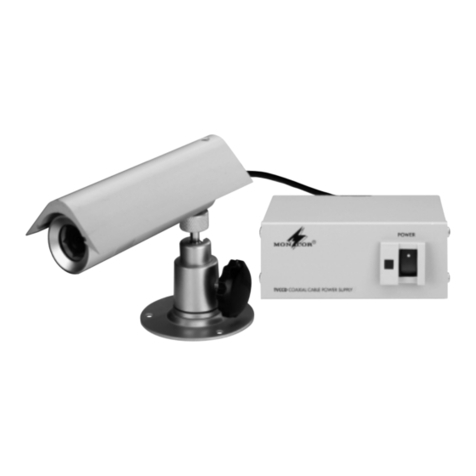
  9. Monacor TVCCD-340COL User manual

Monacor TVCCD-340COL User manual

Minikuppel-Farbkamera
Bitte lesen Sie diese Bedienungsanleitung vor dem Betrieb
gründlich durch und heben Sie sie für ein späteres Nachlesen
auf.
1Einsatzmöglichkeiten
Diese Farbkamera ist speziell für den Einsatz in Video-
überwachungsanlagen (CCTV) konzipiert. Sie ist vandalis-
musgeschützt und verfügt über einen automatischen elektro-
nischen Shutter, eine automatische Verstärkungsregelung
(AGC) und einen automatischen Weißabgleich. Das Modell
TVCCD-340HCOL hat eine besonders hochauflösende Bild-
darstellung (480Linien).
2Wichtige Hinweise für den Gebrauch
Die Kamera entspricht allen erforderlichen Richtlinien der EU
und ist deshalb mit gekennzeichnet.
●Die Kamera ist nur zur Verwendung im Innenbereich geeig-
net. Schützen Sie sie vor Tropf- und Spritzwasser, hoher
Luftfeuchtigkeit und Hitze (zulässiger Einsatztemperaturbe-
reich 0–40°C).
●Berühren Sie das Objektiv nicht mit den Fingern und ver-
wenden Sie für die Reinigung nur Mittel speziell für optische
Linsen.
●Reinigen Sie das Gehäuse nur mit einem weichen, tro-
ckenen Tuch, niemals mit Chemikalien oder Wasser.
●Wird die Kamera zweckentfremdet, falsch angeschlossen
oder nicht fachgerecht repariert, kann keine Haftung für dar-
aus resultierende Sach- oder Personenschäden und keine
Garantie für die Kamera übernommen werden.
Soll die Kamera endgültig aus dem Betrieb
genommen werden, übergeben Sie sie zur
umweltfreundlichen Entsorgung einem örtlichen
Recyclingbetrieb.
3Inbetriebnahme
3.1 Montage
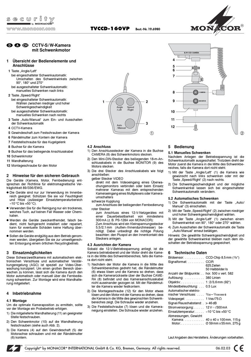
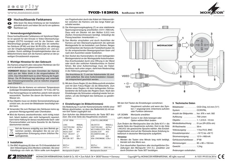
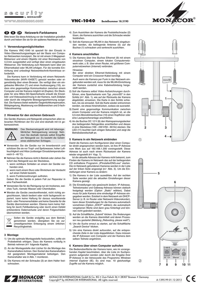
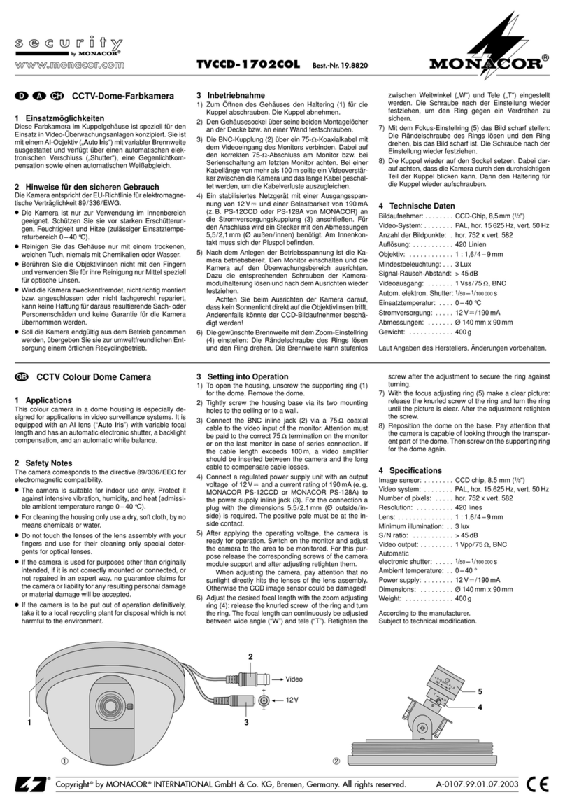
Zur Montage der Kamera die Kuppel (5) und die Sichtblende
(4) abnehmen, damit die Montagelöcher zugängig sind:
1) Die Madenschraube (2) mit dem beiliegenden Inbus-
schlüssel ganz herausdrehen.
2) Zuerst die Kuppel (5) etwas im Uhrzeigersinn bis zum An-
schlag drehen. Erst dann lässt sich der Sicherungsring (3)
abnehmen. Dazu den Inbusschlüssel zur Hilfe nehmen:
Den Schlüssel schräg in das Loch (2) stecken und den
Ring herausheben.
3) Die Kuppel gegen den Uhrzeigersinn wieder bis zum
Anschlag zurückdrehen. Danach lässt sie sich abnehmen.
4) Die schwarze Sichtblende (4) ist mit vier Haltenasen in
einem Ringnut eingerastet. Zum Ausrasten die zwei Hal-
tenasen neben der Sehöffnung kräftig nach innen drücken
[siehe Pfeile (a) in Abb. 1] und die Blende abnehmen.
5) Nun sind die drei Montagelöcher zugängig. An geeigneter
Stelle in die Decke ein Loch zum Durchführen des An-
schlusskabels bohren und die Kamera festschrauben.
3.2 Kamera anschließen
1) Das Videosignal am BNC-Stecker (7) über ein abge-
schirmtes Kabel auf den Videoeingang eines Monitors
geben. Bei einer Kabellänge über 100m sollte zum Aus-
gleich von Pegelverlusten durch das Kabel ein Videover-
stärker (z.B. TW-200SET von MONACOR) zwischen
Kamera und Kabel geschaltet werden.
2) An die Kleinspannungskupplung (6) ein stabilisiertes 12-V-
Netzgerät anschließen (Belastbarkeit siehe Technische
Daten), z.B. PS-500ST von MONACOR. Es wird ein Klein-
spannungsstecker 5,5/2,1mm (Außen-/Innendurchmes-
ser) benötigt. Unbedingt auf die richtige Polung achten:
Den Pluspol an den Mittelkontakt des Steckers anlegen.
3) Die Kamera durch Drehen und Neigen optimal auf den
Überwachungsbereich ausrichten (Kontrolle über den an-
geschlossenen Monitor).
4) Wird das zu überwachende Objekt unscharf abgebildet, die
Fokuseinstellung durch Drehen des Objektivs (1) korrigieren.
3.3 Kamerakuppel wieder aufsetzen
1) Die Sichtblende (4) wieder einrasten und die Blende so
drehen, dass die Kamera durch die Sehöffnung blickt.
2) Die Kuppel aufsetzen und im Uhrzeigersinn bis zum An-
schlag drehen.
3) Den Sicherungsring (3) so auf das Gehäuse legen, dass
dessen Loch über der Gewindebuchse (2) für die Maden-
schraube liegt.
4) Die Kuppel gegen den Uhrzeigersinn bis zum Anschlag
drehen. Der Sicherungsring und die Kuppel sind dadurch
arretiert. Jetzt lässt sich die Madenschraube wieder in die
Gewindebuchse (2) hineinschrauben.
4Technische Daten
Bildabtaster: . . . . . . . . . . . . . . CCD-Chip, 8,5 mm (1/3")
Videosystem: . . . . . . . . . . . . . CCIR, PAL
Anzahl der Bildpunkte: . . . . . . hor. 510 x vert. 492 (TVCCD-340COL)
hor. 752 x vert. 582 (TVCCD-340HCOL)
Auflösung: . . . . . . . . . . . . . . . 350 Linien (TVCCD-340COL)
480 Linien (TVCCD-340HCOL)
Objektiv: . . . . . . . . . . . . . . . . . 1 : 2,0/3,6 mm / 92°
Shutter: . . . . . . . . . . . . . . . . . . 1/50 s bis 1/100 000 s
Mindestbeleuchtung: . . . . . . . . 0,5 Lux (TVCCD-340COL)
1,0 Lux (TVCCD-340HCOL)
Signal/Rausch-Abstand: . . . . . > 48 dB
Videoausgang: . . . . . . . . . . . . 1 Vss/75 Ω
Stromversorgung: . . . . . . . . . . 12 V ±10 %
90 mA (TVCCD-340COL)
160 mA (TVCCD-340HCOL)
Änderungen vorbehalten.
®
TVCCD-340COL
TVCCD-340HCOL
Best.-Nr. 18.0450
Best.-Nr. 18.0460
®
Miniature Dome Colour Camera
Please read these operating instructions carefully prior to
operating the unit and keep them for later use.
1Applications
This colour camera is especially designed for use in video sur-
veillance systems (CCTV). It is protected against vandalism
and equipped with automatic electronic shutter, automatic gain
control (AGC), and automatic white balance. The model
TVCCD-340HCOL has a picture reproduction of especially
high resolution (480 lines).
2Important Notes
The camera corresponds to all required directives of the EU
and is therefore marked with .
●The camera is suitable for indoor use only. Protect it against
dripping water and splash water, high air humidity, and heat
(admissible ambient temperature range 0–40°C).
●Do not touch the lens with your fingers and for cleaning only
use specific cleaning agents for optical lenses.
●For cleaning the housing only use a dry, soft cloth, by no
means chemicals or water.
●No guarantee claims for the camera and no liability for any
resulting personal damage or material damage will be
accepted if the camera is used for other purposes than orig-
inally intended, if it is not correctly connected or not repaired
in an expert way.
If the camera is to be put out of operation defini-
tively, take it to a local recycling plant for a disposal
which is not harmful to the environment.
3Operation
3.1 Mounting
For mounting the camera remove the dome (5) and the cover
(4) so that the mounting holes are accessible:
1) Fully turn out the setscrew (2) with the supplied hexagon
key.
2) First turn the dome (5) slightly clockwise up to the stop.
Then it is possible to remove the safety ring (3). For this
purpose use the hexagon key: Place the key diagonally
into the hole (2) and lift out the ring.
3) Turn back the dome counter-clockwise up to the stop.
Then it can be removed.
4) The black cover (4) is engaged in a ring groove with four
latches. To disengage, press the two latches next to the
visual opening inwards in a powerful way [see arrows (a)
in fig. 1] and remove the cover.
5) Now the three mounting holes are accessible. Drill a hole
at a suitable place in the ceiling to guide the connection
cable and screw down the camera.
3.2 Connecting the camera
1) Feed the video signal at the BNC plug (7) via a screened
cable to the video input of a monitor. With a cable length of
more than 100m a video amplifier (e.g. TW-200SET from
MONACOR) should be inserted between camera and
cable to compensate level loss by the cable.
2) Connect a regulated 12V power supply unit to the low-volt-
age inline jack (6) [for the rating see the specifications],
e.g. PS-500ST from MONACOR. A low-voltage plug
5.5/2.1mm (outside/inside diameter) is required. Observe
the correct polarity in any case: Apply the positive pole to
the centre contact of the plug.
3) By turning and inclining adjust the camera to the surveil-
lance area in an optimum way (check via the connected
monitor).
4) If the object to the monitored is not in focus, correct the
focus setting by turning the lens (1).
3.3 Repositioning the camera dome
1) Engage the cover (4) and turn it so that the camera looks
through the visual opening.
2) Position the dome and turn it clockwise up to the stop.
3) Place the safety ring (3) on the housing so that its hole is
located above the thread jack (2) for the setscrew.
4) Turn the dome counter-clockwise up to the stop. Thus, the
safety ring and the dome are locked. Now the setscrew
can be screwed into the thread jack (2).
4Specifications
Image sensor: . . . . . . . . . . . . CCD chip, 8.5 mm (1/3")
Video system: . . . . . . . . . . . . . CCIR, PAL
Number of pixels: . . . . . . . . . . hor. 510 x vert. 492 (TVCCD-340COL)
hor. 752 x vert. 582 (TVCCD-340HCOL)
Resolution: . . . . . . . . . . . . . . . 350 lines (TVCCD-340COL)
480 lines (TVCCD-340HCOL)
Lens: . . . . . . . . . . . . . . . . . . . 1 : 2.0/3.6 mm/92°
Shutter: . . . . . . . . . . . . . . . . . 1/50 s to 1/100 000 s
Minimum illumination: . . . . . . . 0.5 lux (TVCCD-340COL)
1.0 lux (TVCCD-340HCOL)
S/N ratio: . . . . . . . . . . . . . . . . > 48 dB
Video output: . . . . . . . . . . . . . 1 Vpp / 75 Ω
Power supply: . . . . . . . . . . . . 12 V ±10 %
90 mA (TVCCD-340COL)
160 mA (TVCCD-340HCOL)
Subject to technical modification.
D A CH
GB
Copyright©by MONACOR INTERNATIONAL GmbH & Co. KG, Bremen, Germany. All rights reserved. A-0533.99.01.01.2006
®
®
12V
Video
2
3
4
5
6
7
1
a
a➀➁
Caméra couleur
dans une coupole miniature
Veuillez lire la présente notice avec attention avant le fonctionne-
ment et conservez-la pour pouvoir vous y reporter ultérieurement.
1Possibilités d’utilisation
Cette caméra couleur est spécialement conçue pour une utilisa-
tion dans des installations de vidéosurveillance (CCTV). Elle est
protégée contre les actes de vandalisme et dispose d’une obtu-
ration électronique automatique, d’un réglage automatique
d’amplification (AGC) et d’une compensation automatique du
blanc. Le modèle TVCCD-340HCOL a une représentation des
images avec une résolution particulièrement élevée (480 lignes).
2Conseils d’utilisation
La caméra répond à toutes les directives nécessaires de l’Uni-
on Européenne et porte donc le symbole .
●La caméra n’est conçue que pour une utilisation en intérieur.
Protégez-la de tout type de projections d’eau, des éclabous-
sures, d’une humidité d’air élevée et de la chaleur (plage de
température de fonctionnement autorisée : 0–40°C).
●Ne touchez pas l’objectif avec les doigts et utilisez exclusive-
ment des produits pour lentilles optiques pour le nettoyage.
●Pour nettoyer le boîtier, utilisez un chiffon sec et doux, en
aucun cas de produits chimiques ou d’eau.
●Nous déclinons toute responsabilité en cas de dommages
corporels ou matériels résultants si la caméra est utilisée
dans un but autre que celui pour lequel elle a été conçue, si
elle n’est pas correctement branchée ou n’est pas réparée
par une personne habilitée, de même, la garantie devien-
drait caduque.
Lorsque la caméra est définitivement retirée du
service, vous devez la déposer dans une usine de
recyclage de proximité pour contribuer à son élimi-
nation non polluante.
3Fonctionnement
3.1 Montage
Pour le montage de la caméra, retirez la coupole (5) et le
cache (4) pour accéder aux trous de montage :
1) Retirez entièrement la vis sans tête (2) avec la clé à 6 pans
livrée.
2) Tournez tout d’abord la coupole (5) un peu dans le sens
des aiguilles d’une montre jusqu’à la butée. Ensuite, vous
pouvez retirer l’anneau de sécurité (3) ; utilisez pour vous
aider la clé à six pans: placez la clé dans le trou (2), en
oblique, et retirez l’anneau.
3) Tournez la coupole dans le sens inverse des aiguilles
d’une montre jusqu’à la butée, elle peut alors être retirée.
4) Le cache noir (4) est inséré dans une encoche annulaire
avec quatre languettes. Pour le retirer, appuyez fortement
vers l’intérieur les deux languettes à côté de l’ouverture de
vision [voir flèches (a) sur le schéma 1] et retirez le cache.
5) Les trois trous de montage sont désormais accessibles.
Percez à l’endroit voulu dans le plafond un trou pour faire
passer le câble de branchement et vissez la caméra.
3.2 Branchements de la caméra
1) Appliquez le signal vidéo présent à la fiche BNC (7) via un
câble blindé à l’entrée vidéo d’un moniteur. Pour une lon-
gueur de câble supérieure à 100m, il faudrait brancher
entre la caméra et le câble, un amplificateur vidéo (p.ex.
TW-200SET de MONACOR) pour compenser les pertes
de niveau en ligne.
2) Reliez une alimentation stabilisée 12V (charge voir
données techniques), p.ex. PS-500ST de MONACOR, à
la prise alimentation (6). Un adaptateur aux dimensions
5,5/2,1mm (Ø extérieur/intérieur) est nécessaire. Veillez
à respecter impérativement la polarité : le pôle plus est au
contact médian de la fiche.
3) Orientez la caméra de manière optimale en la tournant et
l’inclinant vers la zone de surveillance (contrôle via le
moniteur relié).
4) Si l’objet à surveiller n’est pas net, corrigez le réglage du
focus en tournant l’objectif (1).
3.3 Repositionnement de la coupole de la caméra
1) Repositionnez le cache (4), enclenchez-le, tournez-le jusqu’à
ce que la caméra puisse voir à travers l’ouverture de vision.
2) Placez la coupole et tournez-la dans le sens des aiguilles
d’une montre jusqu’à la butée.
3) Placez l’anneau de sécurité (3) sur le boîtier de telle sorte
que son trou se trouve au-dessus de la prise filetée (2)
pour la vis sans tête.
4) Tournez la coupole dans le sens inverse des aiguilles
d’une montre jusqu’à la butée ; l’anneau de sécurité et la
coupole sont ainsi bloqués. Vous pouvez maintenant revis-
ser la vis sans tête dans la prise filetée (2).
4Caractéristiques techniques
Puce : . . . . . . . . . . . . . . . . . . puce CCD, 8,5 mm (1/3")
Système vidéo : . . . . . . . . . . . CCIR, PAL
Nombre de points : . . . . . . . . . hor. 510 x vert. 492 (TVCCD-340COL)
hor. 752 x vert. 582 (TVCCD-340HCOL)
Résolution : . . . . . . . . . . . . . . 350 lignes (TVCCD-340COL)
480 lignes (TVCCD-340HCOL)
Objectif : . . . . . . . . . . . . . . . . 1 : 2,0/ 3,6 mm / 92°
Shutter (obturation) : . . . . . . . . 1/50 s à 1/100 000 s
Luminosité minimale : . . . . . . . 0,5 lux (TVCCD-340COL)
1,0 lux (TVCCD-340HCOL)
Rapport signal/bruit : . . . . . . . > 48 dB
Sortie vidéo : . . . . . . . . . . . . . 1 Vcc/75 Ω
Alimentation : . . . . . . . . . . . . . 12 V ±10 %
90 mA (TVCCD-340COL)
160 mA (TVCCD-340HCOL)
Tout droit de modification réservé.
®
TVCCD-340COL
TVCCD-340HCOL
Best.-Nr. 18.0450
Best.-Nr. 18.0460
®
Telecamera a colori a minicupola
Vi preghiamo di leggere attentamente le presenti istruzioni
prima dell’uso e di conservarle per un uso futuro.
1Possibilità d’impiego
Questa telecamera a colori è stata realizzata specialmente
per l’impiego in impianti di sorveglianza video (CCTV). È pro-
tetta contro atti vandalici e dispone di un otturatore elettronico
automatico, di regolamento automatica del guadagno (AGC)
e di bilanciamento automatico del bianco. Il modello
TVCCD-340HCOL offre una rappresentazione particolarmen-
te alta dell’immagine (480 linee).
2Avvertenze importanti
La telecamera è conforme a tutte le direttive richieste dell’UE
e pertanto porta la sigla .
●La telecamera è adatta solo per l’uso all’interno di locali.
Proteggerla dall’acqua gocciolante e dagli spruzzi d’acqua,
da alta umidità dell’aria e dal calore (temperatura d’impiego
ammessa fra 0 e 40°C).
●Non toccare l’obiettivo con le dita e per pulirlo usare solo
mezzi per lenti ottiche.
●Per la pulizia della custodia usare solo un panno morbido,
asciutto; non impiegare in nessun caso prodotti chimici o
acqua.
●Nel caso d’uso improprio, di collegamenti sbagliati o di ripa-
razione non a regola d’arte della telecamera, non si assume
nessuna responsabilità per eventuali danni consequenziali
a persone o a cose e non si assume nessuna garanzia per
la telecamera.
Se si desidera eliminare la telecamera definitiva-
mente, consegnarla per lo smaltimento ad un’isti-
tuzione locale per il riciclaggio.
3Messa in funzione
3.1 Montaggio
Per il montaggio della telecamera togliere la cupola (5) e la
mascherina (4) per rendere accessibili i fori di montaggio:
1) Svitare completamente la vite senza testa (2) servendosi
della chiave a brugola in dotazione.
2) Per prima cosa, girare la cupola (5) un po’ in senso orario
fino all’arresto. Solo a questo punto è possibile togliere
l’anello di sicurezza (3). Per fare ciò aiutarsi con la chiave
a brugola: inserirla in modo obliquo nel foro (2) e togliere
l’anello.
3) Girare di nuovo la cupola in senso antiorario fino all’arre-
sto. Ora la si può togliere.
4) La mascherina nera (4) è fissata ad incastro con quattro
gancini in una scanalatura dell’anello. Per sbloccarla spin-
gere con forza i due gancini vicino all’apertura per l’obiet-
tivo verso l’interno [vedi le frecce (a) in fig. 1] e togliere la
mascherina.
5) Ora i tre fori di montaggio sono accessibili. Praticare in un
punto adatto del soffitto un foro per fare passare il cavo di
collegamento ed avvitare la telecamera.
3.2 Collegare la telecamera
1) Portare il segnale video del connettore BNC (7) sull’ingres-
so video di un monitor servendosi di un cavo schermato.
Se il cavo è più lungo di 100m, si dovrebbe inserire un
amplificatore video (p.es. TW-200SET della MONACOR)
fra telecamera e cavo per compensare le perdite di livello
dovute al cavo.
2) Collegare un alimentatore stabilizzato di 12V (per la poten-
za vedi i dati tecnici), p.es. PS-500ST della MONACOR
con il contatto per alimentazione DC (6). È richiesto uno
spinotto di 5,5/2,1 mm (diametro esterno/interno). Fare
assolutamente attenzione alla corretta polarità: il polo posi-
tivo deve trovarsi sul contatto centrale dello spinotto.
3) Con movimenti in senso orizzontale e verticale orientare la
telecamera in modo ottimale sulla zona da sorvegliare
(controllo per mezzo del monitor collegato).
4) Se l’oggetto da sorvegliare non è a fuoco, correggere la
focale girando l’obiettivo (1).
3.3 Rimettere la cupola della telecamera
1) Fissare ad incastro la mascherina (4) e girarla in modo tale
che l’apertura per l’obiettivo sia libera.
2) Rimettere la cupola e girarla in senso orario fino all’arresto.
3) Posizionare l’anello di sicurezza (3) sul contenitore in
modo tale che i suo fori si trovino sopra la boccola filettata
(2) per la vite senza testa.
4) Girare la cupola in senso antiorario fino all’arresto. L’anel-
lo di sicurezza e la cupola sono così bloccati. A questo
punto è possibile avvitare nuovamente la vite senza testa
nella boccola filettata (2).
4Dati tecnici
Sensore ottico: . . . . . . . . . . . . chip CCD, 8,5 mm (1/3")
Sistema video: . . . . . . . . . . . . CCIR, PAL
Numero pixel: . . . . . . . . . . . . . orizz. 510 x vert. 492 (TVCCD-340COL)
orizz. 752 x vert. 582 (TVCCD-340HCOL)
Risoluzione: . . . . . . . . . . . . . . 350 linee (TVCCD-340COL)
480 linee (TVCCD-340HCOL)
Obiettivo: . . . . . . . . . . . . . . . . 1 : 2,0/3,6 mm /92°
Otturatore: . . . . . . . . . . . . . . . 1/50 s a 1/100 000 s
Illuminazione minima: . . . . . . . 0,5 Lux (TVCCD-340COL)
1,0 Lux (TVCCD-340HCOL)
Rapporto S/R: . . . . . . . . . . . . > 48 dB
Uscita video: . . . . . . . . . . . . . 1 Vpp/75 Ω
Alimentazione: . . . . . . . . . . . . 12 V ±10 %
90 mA (TVCCD-340COL)
160 mA (TVCCD-340HCOL)
Con riserva di modifiche tecniche.
F B CH
I
Copyright©by MONACOR INTERNATIONAL GmbH & Co. KG, Bremen, Germany. All rights reserved. A-0533.99.01.01.2006
®
®
12V
Video
2
3
4
5
6
7
1
a
a➀➁

This manual suits for next models

3

Other Monacor Security Camera manuals

Monacor TVCCD-187HCOL Manual

Monacor

Monacor TVCCD-187HCOL Manual

Monacor TVCCD-160VP User manual

Monacor

Monacor TVCCD-160VP User manual

Monacor TVCCD-316 User manual

Monacor

Monacor TVCCD-316 User manual

Monacor TVCCD-436HCOL User manual

Monacor

Monacor TVCCD-436HCOL User manual

Monacor TVCCD-30M User manual

Monacor

Monacor TVCCD-30M User manual

Monacor INC-4757PTZ User manual

Monacor

Monacor INC-4757PTZ User manual

Monacor TVCCD-32MCOL User manual

Monacor

Monacor TVCCD-32MCOL User manual

Monacor INC-2036DM User manual

Monacor

Monacor INC-2036DM User manual

Monacor TVCCD-30 User manual

Monacor

Monacor TVCCD-30 User manual

Monacor HDCAM-5090IR User manual

Monacor

Monacor HDCAM-5090IR User manual

Monacor INC-1500THERM User manual

Monacor

Monacor INC-1500THERM User manual

Monacor INC-4036MDVP User manual

Monacor

Monacor INC-4036MDVP User manual

Monacor INC-4036DF User manual

Monacor

Monacor INC-4036DF User manual

Monacor TVCCD-310COL User manual

Monacor

Monacor TVCCD-310COL User manual

Monacor HDCAM-5090 User manual

Monacor

Monacor HDCAM-5090 User manual

Monacor TVCCD-170Z User manual

Monacor

Monacor TVCCD-170Z User manual

Monacor TVCCD-800ECOL User manual

Monacor

Monacor TVCCD-800ECOL User manual

Monacor TVCCD-152SET User manual

Monacor

Monacor TVCCD-152SET User manual

Monacor TVCCD-255 User manual

Monacor

Monacor TVCCD-255 User manual

Monacor TVCCD-24M User manual

Monacor

Monacor TVCCD-24M User manual

Monacor TVCCD-140IR User manual

Monacor

Monacor TVCCD-140IR User manual

Monacor TVCCD-312/WS User manual

Monacor

Monacor TVCCD-312/WS User manual

Monacor AV-3033CCD User manual

Monacor

Monacor AV-3033CCD User manual

Monacor TVCCD-34COL User manual

Monacor

Monacor TVCCD-34COL User manual

Popular Security Camera manuals by other brands

Visionhitech VB21S3 Quick installation guide

Visionhitech

Visionhitech VB21S3 Quick installation guide

Hunt CCTV HTC-LP112DID instruction manual

Hunt CCTV

Hunt CCTV HTC-LP112DID instruction manual

InMotion in30S1P1L25 quick start guide

InMotion

InMotion in30S1P1L25 quick start guide

ICRealtime AVS Series quick start guide

ICRealtime

ICRealtime AVS Series quick start guide

Smart watch H20IPSD302 manual

Smart watch

Smart watch H20IPSD302 manual

HIK VISION DS-2CD2763G0-IZS quick start guide

HIK VISION

HIK VISION DS-2CD2763G0-IZS quick start guide

HIK VISION DS-2CD2346G1-l user manual

HIK VISION

HIK VISION DS-2CD2346G1-l user manual

i-PRO WV-X86531-Z2 installation guide

i-PRO

i-PRO WV-X86531-Z2 installation guide

Abus TVIP42562 manual

Abus

Abus TVIP42562 manual

HIK VISION DS-2CE11D0T-PIRL user manual

HIK VISION

HIK VISION DS-2CE11D0T-PIRL user manual

Abus HDCC72551 user manual

Abus

Abus HDCC72551 user manual

Delta OMEGA-PTZ-22P4-4P user manual

Delta

Delta OMEGA-PTZ-22P4-4P user manual

HIK VISION DS-2DF1-57XY Technical manual

HIK VISION

HIK VISION DS-2DF1-57XY Technical manual

i3 International Am52R user manual

i3 International

i3 International Am52R user manual

Alarmcom ADC-V724 installation guide

Alarmcom

Alarmcom ADC-V724 installation guide

i3 International i3-B731 quick start guide

i3 International

i3 International i3-B731 quick start guide

Cam Scan CS-PD6600 manual

Cam Scan

Cam Scan CS-PD6600 manual

Clear One UNITE 160 4K quick start guide

Clear One

Clear One UNITE 160 4K quick start guide

manuals.online logo
manuals.online logoBrands
  • About & Mission
  • Contact us
  • Privacy Policy
  • Terms and Conditions

Copyright 2025 Manuals.Online. All Rights Reserved.