manuals.online logo
Brands
  1. Home
  2. •
  3. Brands
  4. •
  5. Monacor
  6. •
  7. Speakers
  8. •
  9. Monacor EDL-70/WS User manual

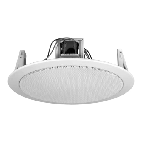
Monacor EDL-70/WS User manual

EDL-70/WS Bestellnummer 16.3310
ELECTRONICS FOR SPECIALISTS ELECTRONICS FOR SPECIALISTS ELECTRONICS FOR SPECIALISTS ELECTRONICS FOR SPECIALISTS
INSTALLATIONSANLEITUNG
INSTALLATION INSTRUCTIONS
NOTICE D’INSTALLATION
ISTRUZIONI PER L‘INSTALLAZIONE
INSTRUCCIONES DE INSTALACIÓN
INSTRUKCJA INSTALACJI
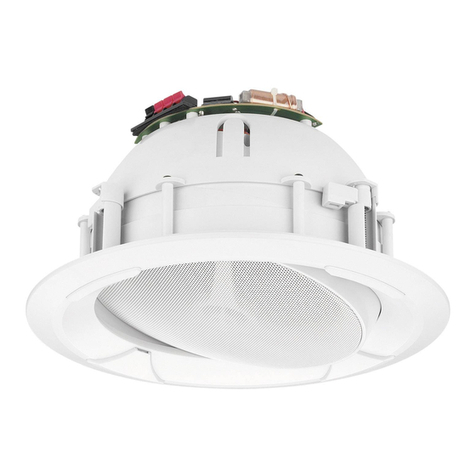
ELA-Deckenlautsprecher
PA Ceiling Speaker
ELA-Deckenlautsprecher
Diese Anleitung richtet sich an Installateure, die
ausreichende Fachkenntnisse in der 100-V-Be-
schallungstechnik besitzen. Bitte lesen Sie die
Anleitung vor der Installation gründlich durch und
heben Sie sie für ein späteres Nachlesen auf.
1 Verwendungsmöglichkeiten
Der Lautsprecher ist für den Einbau in einer
Decke mit einer Stärke von ca. 2 – 45 mm
bestimmt und dient zur Beschallung mit Sprache
und Hintergrundmusik. Er ist speziell für den Ein-
satz in ELA-Anlagen konzipiert, die mit 100-V-
Technik arbeiten. Durch die zweiteilige Ausfüh-
rung (Halterahmen und Lautsprecherchassis) ist
die Montage sehr einfach.
2 Hinweise für den sicheren Gebrauch
Der Lautsprecher entspricht allen relevanten
Richtlinien der EU und deshalb mit gekenn-
zeichnet.
GDer Lautsprecher ist nur zur Verwendung im
Innenbereich geeignet. Schützen Sie ihn vor
Tropf- und Spritzwasser, hoher Luftfeuchtig-
keit und Hitze (zulässiger Einsatztemperatur-
bereich 0 – 40 °C).
GVerwenden Sie zum Reinigen nur ein trocke-
nes, weiches Tuch, auf keinen Fall Wasser
oder Chemikalien.
GWird der Lautsprecher zweckentfremdet, nicht
fachgerecht montiert, falsch angeschlossen
oder überlastet, kann keine Haftung für
daraus resultierende Sach- oder Personen-
schäden und keine Garantie für den Lautspre-
cher übernommen werden.
3 Montage
1) Den weißen Halterahmen festhalten und das
Lautsprecherchassis bis zum Anschlag rechts
herum drehen, sodass das Chassis aus dem
Rahmen genommen werden kann.
2) Die drei Haltefedern des Rahmens
zum Spannen nach oben drücken und
in die Arretierung (Pfeil) einhaken.
VORSICHT! Beim Spannen und
Lösen der Federn besteht durch die
starke Federkraft Verletzungsgefahr.
Halten Sie Ihre Finger nicht zwischen
Rahmen und gespannter Feder!
3) In die Decke ein Loch (∅195 mm) sägen.
4) Den Halterahmen in das Deckenloch einset-
zen und die Federn vorsichtig aus der Arretie-
rung lösen (nicht zurückschnellen lassen),
sodass sie den Rahmen in der Decke halten.
5) Den Anschluss nach Kapitel 4 durchführen.
6) Das Lautsprecherchassis wieder in den Rah-
men einsetzen und bis zum Anschlag drehen,
damit es fest sitzt.
4 Elektrischer Anschluss
1) Vor dem elektrischen Anschluss des Laut-
sprechers die ELA-Anlage komplett ausschal-
ten, damit die 100-V-Audioleitung vom ELA-
Verstärker spannungsfrei ist!
2) Ab Werk ist der Lautsprecher auf eine Nenn-
belastbarkeit von 6 W eingestellt. Für eine
geringere Nennbelastung (Lautstärke) am
Transformator die rote Leitung vom Steck-
kontakt „6 W“ abziehen und auf den Kontakt
stecken, mit dem die gewünschte Nennbelas-
tung (3 W oder 1,5 W) erreicht wird.
3) Den Klemmenblock des Lautsprechers an die
100-V-Audioleitung anschließen. Beim An-
schluss von mehreren Lautsprechern darauf
achten, dass die Lautsprecher alle gleich
gepolt werden (z. B. schwarzer Draht =
Minusanschluss) und dass der ELA-Verstär-
ker nicht überlastet wird.
Änderungen vorbehalten.
WARNUNG Im Betrieb liegt berührungsgefähr-
liche Spannung bis 100 V an der
Lautsprecherleitung an. Die Instal-
lation darf nur durch Fachpersonal
erfolgen.
Achten Sie auf die Belastung des ELA-Verstär-
kers durch die Lautsprecher. Eine Überlastung
kann den Verstärker beschädigen! Die Summe
der Leistungen aller angeschlossenen Laut-
sprecher darf die Verstärkerleistung nicht über-
schreiten.
Soll der Lautsprecher endgültig aus
dem Betrieb genommen werden, über-
geben Sie ihn zur umweltgerechten Ent-
sorgung einem örtlichen Recyclingbe-
trieb.
2
PA Ceiling Speaker
These instructions are intended for installers
with sufficient knowledge in 100 V technology for
PA applications. Please read the instructions
carefully prior to installation and keep them for
later reference.
1 Applications
This speaker is intended for ceiling installation
(ceiling thickness: approx. 2 – 45 mm) and is
used for reproducing speech and background
music. It is specially designed for PA systems
operating with 100 V technology. The two-part
design (holding frame and speaker) makes
installation very easy.
2 Safety Notes
The speaker corresponds to all relevant direc-
tives of the EU and is therefore marked with .
GThe speaker is suitable for indoor use only.
Protect it against dripping water and splash
water, high air humidity and heat (admissible
ambient temperature range: 0 – 40 °C).
GFor cleaning only use a dry, soft cloth; never
use water or chemicals.
GNo guarantee claims for the speaker and no
liability for any resulting personal damage or
material damage will be accepted if the
speaker is used for other purposes than origi-
nally intended, if it is not correctly installed or
connected, or if it is overloaded.
3 Installation
1) Hold the white frame and turn the speaker
clockwise to the stop so that the speaker can
be removed from the frame.
2) To tighten the springs, push the three
retaining springs of the frame upwards
and hook each spring into its catch
(arrow).
CAUTION! When the springs are tight-
ened or released, the tension is high
and there is a risk of injury. Never put
your fingers between the frame and a
spring under tension!
3) Saw a hole (∅195 mm) into the ceiling.
4) Insert the holding frame into the hole in the
ceiling and carefully release each spring from
its catch (avoiding sudden rebound) so that
the springs will hold the frame in the ceiling.
5) Make the connection according to chapter 4.
6) Push the speaker into the frame, then turn the
speaker to the stop so that it is securely fas-
tened.
4 Electrical Connection
1) Completely switch off the PA system before
making the electrical connection so that the
100 V audio cable of the PA amplifier will not
carry any voltage!
2) In the factory, the speaker has been set to a
power rating of 6 W. To reduce the power rat-
ing (volume): On the transformer, disconnect
the red wire from the plug-in contact “6 W”
and connect it to the contact providing the
desired power rating (3 W or 1.5 W).
3) Connect the terminal block of the speaker to
the 100 V audio cable. When connecting mul-
tiple speakers, make sure that all speakers
have the same polarity (e. g. black wire = neg-
ative connection) and that the PA amplifier is
not overloaded.
Subject to technical modification.
WARNING During operation, there is a hazard
of contact with a voltage up to 100 V
at the speaker cable. Installation
must be made by skilled personnel
only.
Observe the load of the PA amplifier by the
speakers. An overload may damage the ampli-
fier! The total load of all speakers connected
must not exceed the amplifier power.
If the speaker is to be put out of opera-
tion definitively, take it to a local recy-
cling plant for a disposal which is not
harmful to the environment.
Ø195
103
Ø 220
2.5
min. 2
max. 45
uçâ
cZhiJ
½
‰
hJö eJö cZ
J
gJö
eZeeJ
½
‰hZhi
J
½
‰
100V AUDIO
fJ
½
jJ
½
uçâ
Technische Daten Specifications EDL-70/WS
Frequenzbereich Frequency range 90 – 20 000 Hz
Nennbelastbarkeit Power rating 6/3/1,5 WRMS
Mittl. Schalldruck (1 W/1 m) SPL (1 W/1 m) 97 dB
Max. Nennschalldruck Max. rated SPL 104 dB
Lautsprechertyp Speaker type 165
Gewicht Weight 1,13 kg
Abmessungen siehe Zeichnung
Angaben in mm
Dimensions see drawing
Values in mm
DeutschEnglish
3
Haut-parleur Public Adress
de plafond
Cette notice sʼadresse aux installateurs possédant
des connaissances suffisantes en technique de
sonorisation ligne 100 V. Veuillez lire la présente
notice avec attention avant l'installation et conser-
vez-la pour pouvoir vous y reporter ultérieurement.
1 Possibilités d'utilisation
Le haut-parleur est prévu pour une installation
dans un plafond dʼune épaisseur de 2 à 45 mm
environ et sert pour une sonorisation de discours
et de musique dʼambiance. Il est spécialement
conçu pour une utilisation dans des installations
Public Adress 100 V. Grâce à sa conception en
deux parties (cadre de maintien et haut-parleur),
son montage est très simple.
2 Conseils dʼutilisation et de sécurité
Le haut-parleur répond à toutes les directives
nécessaires de l'Union européenne et porte
donc le symbole .
GLe haut-parleur n'est conçu que pour une uti-
lisation en intérieur. Protégez-le des écla-
boussures, de tout type de projections d'eau,
dʼune humidité élevée de l'air et de la chaleur
(température ambiante admissible 0 – 40 °C).
GPour le nettoyage, utilisez uniquement un chif-
fon sec et doux, en aucun cas de produits chi-
miques ou d'eau.
G
Nous déclinons toute responsabilité en cas de
dommages matériels ou corporels résultants si le
haut-parleur est utilisé dans un but autre que ce-
lui pour lequel il a été conçu, s'il n'est pas correc-
tement installé ou branché ou sʼil y a surcharge ;
en outre, la garantie deviendrait caduque.
3 Montage
1) Tenez le cadre blanc et tournez le haut-par-
leur vers la droite jusquʼà la butée pour que le
haut-parleur puisse être retiré du cadre.
2) Poussez vers le haut les trois res-
sorts de maintien du cadre pour les
resserrer et accrochez chacun dʼeux
dans lʼarrêtoir correspondant (flèche).
ATTENTION ! Lorsque les ressorts
sont serrés puis desserrés, il y a
risque de blessure à cause de la ten-
sion importante. Ne laissez jamais vos
doigts entre le cadre et les ressorts tendus !
3) Percez un trou (∅195 mm) dans le plafond.
4)
Insérez le cadre de maintien dans le trou du pla-
fond et relâchez les ressorts avec précaution de
leur arrêtoir (évitez tout rebond brusque) pour
quʼils maintiennent le cadre dans le plafond.
5) Effectuez les branchements comme décrit
dans le chapitre 4.
6) Replacez le haut-parleur dans le cadre et
tournez jusquʼà la butée pour quʼil soit bien
maintenu.
4 Branchement électrique
1) Avant de brancher le haut-parleur, éteignez
complètement l'installation Public Adress
pour que le câble audio 100 V de lʼamplifica-
teur PA ne soit pas porteur de tension !
2) En usine, le haut-parleur est réglé sur une
puissance nominale de 6 W. Pour une puis-
sance nominale (volume) plus faible, débran-
chez sur le transformateur audio le câble
rouge du contact “6 W” et reliez-le au contact
correspondant à la puissance nominale sou-
haitée (3 W ou 1,5 W).
3) Reliez le bornier du haut-parleur au câble
audio 100 V. Si vous branchez plusieurs haut-
parleurs, assurez-vous que les haut-parleurs
aient tous la même polarité (p. ex. conducteur
noir = branchement moins) et que lʼamplifica-
teur Public Adress ne soit pas en surcharge.
Tout droit de modification réservé.
Lorsque le haut-parleur est définitivement
retiré du service, vous devez le déposer
dans une usine de recyclage adaptée pour
contribuer à son élimination non polluante.
AVERTISSEMENT Pendant le fonctionnement,
une tension de contact dange-
reuse jusquʼà 100 V est pré-
sente au câble haut-parleur.
Seul un personnel qualifié peut
effectuer l'installation.
Faites attention à la charge de l'amplificateur
PA par les haut-parleurs. Une surcharge peut
endommager l'amplificateur ! La somme des
puissances de l'ensemble des haut-parleurs re-
liés ne doit pas dépasser la puissance de l'am-
plificateur.
Diffusore PA da soffitto
Queste istruzioni sono rivolte agli installatori che
possiedono delle conoscenze specifiche suffi-
cienti della tecnica di sonorizzazione a 100 V. Vi
preghiamo di leggerle attentamente prima del-
l'installazione e di conservarle per un uso futuro.
1 Possibilità d'impiego
Il diffusore è previsto per il montaggio in un sof-
fitto dallo spessore di 2 – 45 mm ca. e serve per
la sonorizzazione a voce e con musica di sotto-
fondo. È stato realizzato specialmente per l'im-
piego in impianti PA che funzionano con uscita
audio 100 V. Grazie alla versione in due parti
(telaio e altoparlante), il montaggio è molto sem-
plice.
2 Avvertenze per l'uso sicuro
Il diffusore è conforme a tutte le direttive rilevanti
dellʼUE e pertanto porta la sigla .
GIl diffusore è previsto solo per lʼuso allʼinterno
di locali. Proteggerlo dall'acqua gocciolante e
dagli spruzzi d'acqua, da alta umidità dell'aria
e dal calore (temperatura dʼimpiego ammessa
fra 0 e 40 °C).
GPer la pulizia usare solo un panno morbido,
asciutto; non impiegare in nessun caso acqua
o prodotti chimici.
GNel caso dʼuso improprio, di montaggio non a
regola d'arte, di collegamenti sbagliati, o di
sovraccarico del diffusore, non si assume
nessuna responsabilità per eventuali danni
consequenziali a persone o a cose e non si
assume nessuna garanzia per il diffusore.
3 Montaggio
1) Tener fermo il telaio bianco e girare verso
destra l'altoparlante fino all'arresto in modo
da poterlo togliere dal telaio.
2) Per tendere le tre molle di supporto del
telaio, spingerle verso l'alto e aggan-
ciarle nella loro sede (freccia).
ATTENZIONE! Tendendo e rila-
sciando le molle, per via della loro
grande forza, esiste il pericolo di farsi
male. Non tenere le dita fra telaio e
molla tesa!
3) Applicare un foro nel soffitto (∅195 mm).
4) Inserire il telaio nel foro e staccare le molle
delicatamente dalla loro sede (non farle scat-
tare) in modo che tengano il telaio fermo nel
soffitto.
5) Eseguire la connessione come descritto nel
capitolo 4.
6) Rimettere l'altoparlante nel telaio e girarlo fino
all'arresto per una sistemazione solida.
4 Collegamento elettrico
1) Prima del collegamento elettrico dell'altopar-
lante spegnere completamente l'impianto PA
perché la linea 100 V dall'amplificatore PA sia
priva di tensione!
2) Dalla fabbrica, sul diffusore è impostata una
potenza nominale di 6 W. Per ottenere una
potenza nominale minore (volume), sul tra-
sformatore sfilare il cavetto rosso dal contatto
“6 W“ e inserirlo sul contatto con il quale si
raggiunge la potenza nominale richiesta (3 W
o 1,5 W).
3) Collegare la morsettiera del diffusore con la
linea audio 100 V. Se si collegano più diffu-
sori, fare attenzione all'identica polarità di tutti
gli altoparlanti (p. es. filo nero = polo negativo)
e di non sovraccaricare l'amplificatore PA.
Con riserva di modifiche tecniche.
AVVERTIMENTO Durante il funzionamento, nel
cavo dell'altoparlante è presente
una tensione fino a 100 V, peri-
colosa in caso di contatto. L'in-
stallazione deve essere eseguita
solo da personale specializzato.
Tener presente anche il carico dell'amplificatore
da parte degli altoparlanti. Un sovraccarico può
danneggiare l'amplificatore! La somma delle
potenze di tutti gli altoparlanti collegati non deve
superare la potenza dell'amplificatore.
Se si desidera eliminare il diffusore defi-
nitivamente, consegnarlo per lo smalti-
mento ad un'istituzione locale per il rici-
claggio.
FrançaisItaliano
Caractéristiques techniques Dati tecnici EDL-70/WS
Bande passante Gamma di frequenze 90 – 20 000 Hz
Puissance nominale Potenza nominale 6/3/1,5 WRMS
Pression sonore moyenne (1 W/1 m) Pressione sonora media (1 W/1 m) 97 dB
Pression sonore nominale maximale Pressione sonora nominale max. 104 dB
Type haut-parleur Tipo altoparlante 165
Poids Peso 1,13 kg
Dimensions, voir dessin
Données en mm
Dimensioni vedi disegno
Dati in mm
Ø195
103
Ø 220
2.5
min. 2
max. 45
uçâ
cZhiJ
½
‰
hJö eJö cZ
J
gJö
eZeeJ
½
‰hZhi
J
½
‰
100V AUDIO
fJ
½
jJ
½
uçâ
Altavoz de techo para megafonía
Estas instrucciones van dirigidas a instaladores
con un conocimiento suficiente sobre la tecnolo-
gía de 100 V en aplicaciones para megafonía.
Lea atentamente estas instrucciones antes de la
instalación y guárdelas para usos posteriores.
1 Aplicaciones
Este altavoz está pensado para instalarse en
techos (grosor del techo: 2 – 45 mm aprox.) y
para reproducir voz y música de fondo. Está
diseñado especialmente para sistemas de
megafonía que funcionan a 100 V. El diseño de
dos piezas (marco de soporte y altavoz) hace
que la instalación sea muy sencilla.
2 Notas de Seguridad
El altavoz cumple con todas las directivas rele-
vantes de la UE y por lo tanto está marcado con
el símbolo .
GEl altavoz está adecuado sólo para aplicacio-
nes en interiores. Protéjalo de goteos y salpi-
caduras, elevada humedad del aire y calor
(temperatura ambiente admisible: 0 – 40 ºC).
GUtilice sólo un paño suave y seco para la lim-
pieza; no utilice nunca ni agua ni productos
químicos.
GNo podrá reclamarse garantía o responsabili-
dad alguna por cualquier daño personal o
material resultante si el altavoz se utiliza para
otros fines diferentes a los originalmente con-
cebidos, si no se instala o no se conecta ade-
cuadamente o si se sobrecarga.
3 Instalación
1) Sujete el marco blanco y gire el altavoz en
sentido horario hasta el tope de modo que se
pueda extraer el altavoz del marco.
2) Para tensar los resortes, tire de los tres
resortes de retención del marco hacia
arriba y enganche cada resorte en su
agarre (flecha).
¡PRECAUCIÓN! Cuando se tensan o
se aflojan los resortes, la tensión es
alta y hay riesgo de lesión. ¡No ponga
nunca los dedos entre el marco y un
resorte en tensión!
3) Haga un agujero (∅195 mm) en el techo.
4) Inserte el marco de soporte en el agujero del
techo y libere cuidadosamente cada resorte
de su agarre (evitando rebotes repentinos) de
modo que los resortes mantengan el marco
en el techo.
5) Haga la conexión según el apartado 4.
6) Presione el altavoz hacia dentro del marco,
luego gire el altavoz hasta el tope para que
quede fijado con seguridad.
4 Conexión Eléctrica
1) ¡Desconecte completamente el sistema de
megafonía antes de realizar la conexión eléc-
trica para que el cable de audio de 100 V del
amplificador no contenga ningún voltaje!
2) Los altavoces vienen de fábrica con una
potencia ajustada en 6 W. Para reducir el
nivel de potencia (volumen): En el transfor-
mador, desconecte el cable rojo del contacto
“6 W” y conéctelo al contacto que ofrezca la
potencia deseada (3 W o 1,5 W).
3) Conecte el bloque de terminales del altavoz al
cable de audio de 100 V. Al conectar varios
altavoces, asegúrese de que todos los altavo-
ces tienen la misma polaridad (p. ej. cable
negro = conexión negativa) y que el amplifica-
dor no está sobrecargado.
Sujeto a modificaciones técnicas.
Si va a poner el altavoz fuera de servi-
cio definitivamente, llévelo a la planta
de reciclaje de la zona para que su eli-
minación no sea perjudicial para el
medio ambiente.
ADVERTENCIA Durante el funcionamiento, hay
peligro de contacto con un vol-
taje de hasta 100 V en el cable
de altavoz. Sólo un técnico debe
realizar la instalación.
Preste atención a la carga del amplificador de
megafonía con los altavoces. ¡Una sobrecarga
podría dañar el amplificador! La carga total de
todos los altavoces conectados no puede exce-
der la potencia del amplificador.
MONACOR INTERNATIONAL GmbH & Co. KG • Zum Falsch 36 • 28307 Bremen • Germany
Copyright©by MONACOR INTERNATIONAL. All rights reserved. A-1626.99.01.01.2015
®
Głośnik sufitowy PA
Niniejsza instrukcja przeznaczona jest instalato-
rów posiadających wiedzę w zakresie systemów
PA pracujących w technice 100 V. Przed rozpo-
częciem użytkowania proszę zapoznać się z
instrukcją, a następnie zachować ją do wglądu.
1 Zastosowanie
Niniejszy głośnik przystosowany jest do mon-
tażu w suficie podwieszanym (o grubości płyty
około 2 – 45 mm) i przeznaczony do odtwarzania
tła muzycznego i komunikatów głosowych. Głoś-
nik przystosowany jest do pracy w systemach
PA wykorzystujących technikę 100 V. Dzięki
dwuczęściowej budowie (ramka i głośnik) i spe-
cjalnym zaczepom na ramce montażowej, mon-
taż głośnika jest bardzo łatwy.
2 Środki bezpieczeństwa
Głośnik spełnia wszystkie wymagania norm UE
dzięki temu został oznaczony symbolem .
GGłośnik przeznaczony jest tylko do zastoso-
wań wewnętrznych. Należy chronić go przez
wodą, dużą wilgotnością oraz wysokimi tem-
peraturami (dopuszczalny zakres 0 – 40 °C).
GDo czyszczenia należy używać suchej i mięk-
kiej ściereczki, nie używać wody ani środków
chemicznych.
GProducent i dostawca nie ponoszą odpowie-
dzialności za powstałe szkody: uszkodzenia
sprzętu bądź obrażenia użytkownika, jeżeli
głośnik był używany niezgodnie z przeznacze-
niem, niepoprawnie zainstalowany, podłą-
czony lub przeciążony.
3 Montaż
1) Trzymając ramkę przekręcić głośnik przeciw-
nie do ruchu wskazówek zegara, aż odczepi
się od ramki montażowej.
2) Podciągnąć do góry trzy sprężyny
zaczepów montażowych na ramce i
zaczepić je w oznaczonym miejscu
(strzałka).
UWAGA! Przy zwalnianiu zaczepów,
należy uważać na palce, gdyż siła
naciągu sprężyn jest bardzo duża i
może spowodować uszkodzenia ciała!
3) W odpowiednim miejscu w suficie wyciąć
okrągły otwór o średnicy ∅195 mm.
4) Umieścić ramkę montażową w otworze i
ostrożnie zwolnić sprężyny zaczepów (unik-
nąć silnego uderzenia), ramka zostanie za-
montowana w suficie.
5) Podłączyć kabel zgodnie z opisem w roz-
dziale 4.
6) Wsunąć głośnik do ramki montażowej i prze-
kręcić do końca w celu zamontowania.
4 Podłączanie
1) Przed przystąpieniem do podłączania głośni-
ków należy odłączyć zasilanie całego sys-
temu PA, aby kabel głośnikowy 100 V nie
znajdował się pod napięciem!
2) Przy fabrycznym ustawieniu, głośnik usta-
wiony jest na moc 6 W. Aby zredukować moc
(głośność) przełączyć czerwony kabel od
styku 6 W transformatora audio na złącze o
żądanej mocy (3 W lub 1,5 W).
3) Podłączyć kabel głośnikowy 100 V do termi-
nala na głośniku. Przy podłączaniu kilku głoś-
ników, należy zwrócić uwagę, aby wszystkie
głośniki miały jednakową polaryzację (np.
czarna żyła = ujemny biegun) i wzmacniacz
nie został przeciążony.
Z zastrzeżeniem możliwości zmian.
UWAGA W czasie pracy, na złączach
występuje niebezpieczne wysokie
napięcie 100 V. Instalacja powinna
być wykonywana wyłącznie przez
przeszkolony personel.
Należy zwrócić uwagę na obciążenie wzmac-
niacza przez głośniki. Przeciążenie wzmacnia-
cza spowoduje jego uszkodzenie! Sumaryczna
moc głośników nie może przekraczać mocy
wzmacniacza.
Jeśli głośnik nie będzie już więcej uży-
wany, wskazane jest przekazanie go do
miejsca utylizacji odpadów, aby został
zniszczony bez szkody dla środowiska.
EspañolPolski
Especificaciones Specyfikacja EDL-70/WS
Rango de frecuencias Pasmo przenoszenia 90 – 20 000 Hz
Potencia nominal Moc 6/3/1,5 WRMS
SPL (1 W/1 m) SPL (1 W/1 m) 97 dB
SPL máx. Max poziom SPL 104 dB
Tipo de altavoz Rozmiar głośnika 165
Peso Waga 1,13 kg
Dimensiones ver esquema
Valores en mm
Wymiary patrz rysunek
Wartości podano w mm
Ø195
103
Ø 220
2.5
min. 2
max. 45
uçâ
cZhiJ
½
‰
hJö eJö cZ
J
gJö
eZeeJ
½
‰hZhi
J
½
‰
100V AUDIO
fJ
½
jJ
½
uçâ

Other Monacor Speakers manuals

Monacor EDL-15 User manual

Monacor

Monacor EDL-15 User manual

Monacor EDL-603 User manual

Monacor

Monacor EDL-603 User manual

Monacor NR-22KS User manual

Monacor

Monacor NR-22KS User manual

Monacor ESP-70/WS User manual

Monacor

Monacor ESP-70/WS User manual

Monacor TM-22 User manual

Monacor

Monacor TM-22 User manual

Monacor PA EDL-35 User manual

Monacor

Monacor PA EDL-35 User manual

Monacor EDL-204 User manual

Monacor

Monacor EDL-204 User manual

Monacor TXA-1022CD User manual

Monacor

Monacor TXA-1022CD User manual

Monacor CARPOWER NEOVOX-130 User manual

Monacor

Monacor CARPOWER NEOVOX-130 User manual

Monacor TM-17 User manual

Monacor

Monacor TM-17 User manual

Monacor UWS-100 User manual

Monacor

Monacor UWS-100 User manual

Monacor EDL-112/W User manual

Monacor

Monacor EDL-112/W User manual

Monacor EDL-82/ WS User manual

Monacor

Monacor EDL-82/ WS User manual

Monacor TM-17 User manual

Monacor

Monacor TM-17 User manual

Monacor EDL-10TW/WS User manual

Monacor

Monacor EDL-10TW/WS User manual

Monacor EX-1 User manual

Monacor

Monacor EX-1 User manual

Monacor WALL-05DTM/WS User manual

Monacor

Monacor WALL-05DTM/WS User manual

Monacor TM-22 User manual

Monacor

Monacor TM-22 User manual

Monacor TM-45 User manual

Monacor

Monacor TM-45 User manual

Monacor ETS-120 SL/WS User manual

Monacor

Monacor ETS-120 SL/WS User manual

Monacor SPE-230BT Quick guide

Monacor

Monacor SPE-230BT Quick guide

Monacor EDL-100/WS User manual

Monacor

Monacor EDL-100/WS User manual

Monacor EDL-706 User manual

Monacor

Monacor EDL-706 User manual

Monacor IT-400TW User manual

Monacor

Monacor IT-400TW User manual

Popular Speakers manuals by other brands

Xtreme Terra XBS9-1056 user manual

Xtreme

Xtreme Terra XBS9-1056 user manual

Sunfire Speaker user manual

Sunfire

Sunfire Speaker user manual

Fire Chief HMP4 instruction manual

Fire Chief

Fire Chief HMP4 instruction manual

Speed Link SL-8906-WE manual

Speed Link

Speed Link SL-8906-WE manual

dB Technologies CROMO 8+ Brochure & specs

dB Technologies

dB Technologies CROMO 8+ Brochure & specs

Phase Technologies PC-1.1 II owner's manual

Phase Technologies

Phase Technologies PC-1.1 II owner's manual

Mark MAM 100 TROLLEY user manual

Mark

Mark MAM 100 TROLLEY user manual

Sound Tube Audio Speaker RS801i datasheet

Sound Tube

Sound Tube Audio Speaker RS801i datasheet

Sky Wing BOOMBAR+ manual

Sky Wing

Sky Wing BOOMBAR+ manual

Phase Technologies Solaris ATS-1 Owner's Manual & Installation Instructions

Phase Technologies

Phase Technologies Solaris ATS-1 Owner's Manual & Installation Instructions

Smart Technologies SBA-150c Installation instructions manual

Smart Technologies

Smart Technologies SBA-150c Installation instructions manual

Martin Audio LE1200S - SCHEMATICS manual

Martin Audio

Martin Audio LE1200S - SCHEMATICS manual

Bluesound PULSE MINI 2i Quick setup guide

Bluesound

Bluesound PULSE MINI 2i Quick setup guide

Silvercrest SMA 500 A1 operating instructions

Silvercrest

Silvercrest SMA 500 A1 operating instructions

Xtreme XTQ300 user guide

Xtreme

Xtreme XTQ300 user guide

Power bass 3XL-653 Guide

Power bass

Power bass 3XL-653 Guide

TRU Audio Ghost GP-4 Instructions guide and user manual

TRU Audio

TRU Audio Ghost GP-4 Instructions guide and user manual

WorkPro SN SUB 8 SoundNut Series user manual

WorkPro

WorkPro SN SUB 8 SoundNut Series user manual

manuals.online logo
manuals.online logoBrands
  • About & Mission
  • Contact us
  • Privacy Policy
  • Terms and Conditions

Copyright 2025 Manuals.Online. All Rights Reserved.