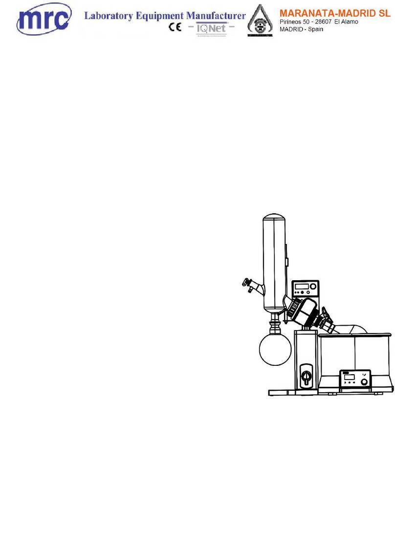
MRC ROVAP Series User manual

ROVAP-SERIES
High Throughput Vacuum Parallel Evaporator
Instruction Manual
This user manual needs to be read before operating this product
Please follow the safety instructions provided in this manual
MRC. 8.22

Content
.............................................................................................................................2
...............................................................................................................................3
................................................................................................................ 3
DANGER: For damage and danger caused by improper use is the sole
responsibility of the user.
................................................................................................................. 3
........................................................................................................... 3
................................................................................................................................. 4
2.3.1 Dangerous vapor....................................................................................................................4
2.3.2 High internal pressure........................................................................................................ 5
2.3.3 Hot surfaces and liquid........................................................................................................ 5
2.3.4 broken glass............................................................................................................................ 5
2.3.5 Failure in operation............................................................................................................... 5
2.3.6 Personal Protective Equipment.........................................................................................5
2.3.7 Retrofit...................................................................................................................................... 6
............................................................................................................................6
.............................................................................................................7
Storage and transportation environmental requirements............................................ 7
Material Instructions............................................................................................................... 7
................................................................................................................7
4.2.2 Rear view................................................................................................................................ 10
4.2.3 Water supply and drainage connection diagram................................................... 11
4.2.4 External electrical connection of equipment diagram............................................... 11
................................................................................................................12
4.3.1 Water shortage detection component............................................................................... 12
4.3.2 Heater overheat protection component........................................................................... 12
4.3.3 Over-current Protection component...............................................................................13
................................................................................................................................... 13
........................................................................................................................ 14
6.2.1 Installation model A condensing system...................................................................15
6.2.2 Installation model B condensing system..................................................................16
6.2.2.1 Installation of glass condenser.................................................................................... 16
6.2.2.2 Installation of cooling circulator pipeline................................................................. 17
6.2.2.3 installation of vacuum pump pipeline...................................................................... 18
...................................................................................................................... 19

.......................................................................................................................20
.................................................................................................................21
.......................................................................................................................21
................................................................................................. 22
.............................................................................................. 22
................................................................................................................ 22
............................................................................................................23
................................................................................................................ 23
..........................................................................................................................24
9.2.1 Method display interface................................................................................................. 26
9.2.1.1 Method setting interface.............................................................................................. 27
9.2.2 Solvent Reference Interface................................................................................................28
9.2.3 Setting interface................................................................................................................... 29
9.2.3.1 Basic setting interface..................................................................................................... 30
9.2.3.2 Function setting interface.............................................................................................. 30
9.2.3.3 User management interface.......................................................................................... 31
9.2.3.4 Operation record interface..............................................................................................32
9.2.3.5 Equipment information interface................................................................................. 33
9.2.3.6 Cover plate temperature setting interface..................................................................34
9.3 Software alarm information description............................................................................ 35
10. Cleaning and maintance ....................................................................................................... 36
10.1 Bottle seal replacement ........................................................................................................ 36
11. Other instructions .....................................................................................................................37
11.1 Replacement of sample adapter......................................................................................... 37
12.Optional items ............................................................................................................................ 38

1
Dear users, thank you for choosing MRC High Throughput Vacuum Parallel
Evaporator. This equipment is mainly used in the field of organic analysis
and testing,which rapidly concentrates the sample under reduced pressure.
MRC RovaP High Throughput Vacuum Parallel Evaporator was developed
and manufactured in accordance with the most advanced level of scientific
and technological knowledge. However, personal injury, property damage, or
environmental damage can still occur if the equipment is used incorrectly. In
order to ensure the safety of users, users should have chemical-related
professional knowledge, and be sure to read this manual carefully before
use.
If you have any questions during use, you can call our free service:
972-3-5595252, we will provide you with fast and excellent quality service.
please log on to our website: www.mrclab.com to get updated news.

2
This instruction manual is used to describe MRC High Throughput Vacuum Parallel Evaporator
as delivered, which is part of the product and contains important information for safe
.operation and maintenance of the equipment
This instruction manual applies to MRC High Throughput Vacuum Parallel Evaporator and for
.use by operation person
To ensure safe and trouble-free operation, please read this operation manual and follow all
instructions before putting the equipment into operation
Please keep this instruction manual near the equipment
Please pass this instruction manual to the next owner or user
MRC Co., Ltd. will not assume any damage or malfunction caused by failure to comply with
this operation manual
please contact customer service department of MRC Co., Ltd
if you have any questions after reading this instruction manual.
Warning tips are used to warn of possible hazards during the use of the equipment.
There are four levels of danger, which can be identified by signal words:
Signal words
Meaning
Dangerous
Indicates a high hazard, if not avoided, will result in death or serious
injury.
Warning
Indicates a moderate hazard , if not avoided, could result in death
or serious injury.
Caution
Indicates a low risk, if not avoided, could result in minor or
moderate injury.
Notice
Indicates a hazard of property damage

3
The following warning signs may appear in this manual or on the equipment
Symbol
Meaning
High temperature on the surface of the object, be careful to
scald!
Do not put your fingers into the gap, and be careful that your
hands are squeezed!
Beware of broken glass causing injury!
Beware of harmful gas poisoning!
The RovaP series vacuum parallel evaporator is not allowed to be used as the
following conditions
◆ Under an environment with explosion danger and explosion- proof equipment;
◆ Manufacturing substances that can cause spontaneous reactions, such as
explosives, metal hydrides or solvents that can generate peroxides;
◆ Working in explosive gas mixtures;
◆ Distillation of oil;
◆ Drying hard, brittle substances (such as stone and soil samples) that can
damage vials;
◆ Sudden cooling of evaporating flasks and other glass parts;
DANGER: For damage and danger caused by improper use is the sole responsibility of the
user.
The RovaP series vacuum parallel evaporator is only permitted by appropriately qualified
laboratory personnel for that persons without the appropriated qualifications cannot identify
risks have greater danger when using

4
This operation manual is intended for the following person:
1) Operating person
The Operating person are those who meet the following standards:
◆ they were assigned to operate on this equipment.
◆ They understand the contents of this operating manual and the current safety
regulations and can apply them.
◆ They are able to assess the possible hazards associated with the use of this
equipment based on their training and professional experience.
2) Operator
Operator (laboratory manager) shall be responsible for the following items:
◆ The equipment must be installed, debugged, operated and maintained
correctly;
◆ Only qualified personnel are allowed to accept the entrustment to carry out the
work described in this operation manual;
◆ Staff must abide by local applicable regulations on labor safety and hazard
protection;
◆ The manufacturer should be notified of safety-related events during equipment
operation;
This equipment has been developed and manufactured in accordance with the most
advanced level of scientific and technological knowledge. However, personal injury,
property damage, or environmental damage may still occur if the equipment is used
improperly.
The corresponding warnings in this manual are used to alert users these other risks.
2.3.1 Dangerous vapor
Hazardous vapors may be generated during use of the equipment, which can lead to
poisoning and life-threatening conditions.
The RovaP series vacuum parallel evaporator must be equipped with a steam
condensing unit;
◆ Do not inhale the vapor generated during use;
◆ The dangerous gas discharged will discharge from the vacuum pump, so

5
the equipment can only be used in a well-ventilated environment for that
◆ If steam escapes from the connection, check the corresponding seal and
replace if necessary.
2.3.2 High internal pressure
High internal pressure may be created in the vial or in the condenser through the
evaporation of the liquid. Excessive pressure may cause the glass parts to explode. Please
make sure that the vacuum pump and condensing unit are working properly to use this
equipment.
2.3.3 Hot surfaces and liquid
The cover plate , water bath box and sample bottles maybe become very hot . Contact with these
parts may cause skin burns.
2.3.4 broken glass
Broken glass can cause cuts.
◆ The collection bottle and other glass parts must be handled with care and
must not be fall.
◆ Before each use, visually inspect whether the appearance of the glass parts is in
good condition.
◆ Damaged glass parts shall not be used.
◆ Remove broken glass only when wearing protective cut-resistant gloves.
2.3.5 Failure in operation
Sharp edges or exposed wires can cause injury if the equipment is damaged.
◆ Check the equipment regularly for damage;
◆ In case of failure, immediately shut down the equipment, cut off the power
supply and notify the operator.
◆ Do not continue to use damaged equipment.
2.3.6 Personal Protective Equipment
Due to different application, hazards can be created for high temperatures, glass breakage
and aggressive chemicals.
◆ When using and maintaining the equipment, we must wear appropriate
protective equipment such as goggles, protective clothing and gloves .
◆ Ensure that protective equipment meets the requirements in the safety data
sheets for each chemical used.

6
2.3.7 Retrofit
◆ Equipment changes not approved by the manufacturer may affect safety and
lead to accidents.
◆ Only use accessories and spare parts and consumable materials provided by the
manufacturer.
◆ Technical changes to equipment or accessories can only be made with the prior
written approval of Beijing MRC Co., Ltd. and only by authorized MRC Co., Ltd.
technicians
Notes
:
MRC
Co.,
Ltd.
will
not
be
liable
for
damage
caused
by
unauthorized
equipment
changes
Models
RovaP-4RovaP-9RovaP-16 RovaP-36
Number of samples
4
9
16
36
Sample bottle volume
800ml
450ml
250ml
60ml
Recommend sample
volume
≤ 400ml
≤ 200ml
≤ 100ml
≤ 30ml
Temperature range
Room temperature
+5℃~85℃
Room temperature
+5℃~85℃
Room temperature
+5℃~85℃
Room temperature
+5℃~85℃
Temperature stability
±1℃
±1℃
±1℃
±1℃
Vacuum cover
temperature setting
range
Room temperature
+5℃~70℃
Room temperature
+5℃~70℃
Room temperature
+5℃~70℃
Room temperature
+5℃~70℃
Vacuum gradient control
Support
Support
Support
Support
Vacuum fast lock
Support
Support
Support
Support
Net weight
62kg
62kg
62kg
62kg
Overall dimensions
W*L*H(mm)
420x 530x 360
420x 530x 360
420x 530x 360
420x 530x 360
Input voltage
AC220V 50/60Hz
AC220V 50/60Hz
AC220V 50/60Hz
AC220V 50/60Hz
Input power
3000W
3000W
3000W
3000W

7
Max. application altitude
≤2000 m
Ambient conditions
Indoor
Ambient temperature
5℃-35℃
Max.relative air humidity
80 % (when temperature less than 31 °C)
40 °C ,Linearly down to 50 %
Storage and transportation environmental requirements
Ambient temperature
-25℃-55℃
Max.relative air humidity
90 % @25℃
Material Instructions
Parts
Material
Outer covering
Q235 steel surface spray, aluminum oxide
Water bath
polycarbonate
Parts in contact with sample
and sample vapor
PEEK, PTFE, glass, perfluoroether rubber
Note: The concentrated samples should not contain solvents that dissolve, swell, and
corrode PEEK, PTFE, glass, and perfluoroether rubber, otherwise the equipment will be
seriously damaged, and the risk will be borne by the user.
This equipment is mainly applied in the field of organic analysis and testing, which
equipped with a vacuum pump and a condensing device to heat and concentrate batch
liquid samples in a decompressed environment. RovaP- series vacuum parallel evaporator
provides users with rich functions;
◆ Sample heating

8
Sample heated by controlling waterbathtemperaturetoaccelerateconcentrationof sample;
Vacuum control
Accelerates sample concentration by controlling the vacuum inside sample bottle.
Meanwhile the equipment has function of vacuum gradient control, so that vacuum
degree can gradually approaches target value, preventing the vacuum degree from
rising too fast , resulting in the sample to boil
Vacuum lock function
If sample heating temperature is known, but vacuum parameters are unknown,
equipment can run first, when there have drip liquid in condensation system ,quickly
press vacuum lock button on LCD touch screen,and vacuum degree will be locked in
current suitable value
Sample preheating
when sample preheating model is enabled, vacuum pump must be start after sample is
preheated according to set time value, avoiding sample explosive boiling
Cover plate heating
Cover plate can be heated according to set temperature, to avoid steam
condensation ,resulting in poor vacuum degree and liquid reflux
Sample oscillation
Sample in the evaporating flask can be vortexed according to the set rotation speed,
which can avoid the bumping of the sample and increase surface area of sample to
achieve purpose of accelerating concentration
Cover plate automatic locking
After equipment running, press down handle of cover plate, the cover plate can be
automatically latched and locked, which can simply seal the cover plate and the sample
bottle mouth. When equipment stop running, vacuum degree drops to about 900mbar,
the locking device inactivates automatically to easily taken out sample bottle
Automatic filling water
Press water replenishment button on touch screen to fill water bath by RovaP-SERIES
own water pump

9
4.2.1 Axonometric projection
Fig.1 Axonometric projection
1 Vacuum adjustment knob; 2 LCD touch screen; 3 Water bath; 4 Sample bottle adapter; 5 Sample bottle;
6 on-off button 7 cover plate; 8 cover plate handle; 9 attracting magnet; 10 vacuum pump power socket;
11 heating reset button; 12 bottle seal; 13 drain valve;14Gas output of condensing device;
valve; 14 Gas output port of condensing device .

10
4.2.2 Rear view
Fig.2 Rear view
1 Vacuum pump inlet port; 2 Condensing device gas input port; 3 USB memory interface;
4 Air inlet; 5 water flood pump

11
4.2.3 Water supply and drainage connection diagram
Fig.3 Water supply and drainage connection diagram
4.2.4 External electrical connection of equipment diagram
Fig.4 External electrical connection of equipment diagram
1 Water bath heating control line; 2 Circulating water pump control line; 3 cover plate
heating control line; 4 Backlight control line; 5 Main unit power line

12
4.2.5 Nameplate information
AH.VPXX-XXXX-XXXX
Fig.5 Nameplate information
4.3.1 Water shortage detection component
Built-in water flow sensor. If water bath is short of water, the equipment will stop heating, and a
water shortage alarm message will appear on touch screen;
4.3.2 Heater overheat protection component
Built-in overheat protector. If water bath is seriously lacking in water or equipment fails,
the heater power supply will disconnect . when water filling is completed or the failure is
removed, equipment can only work normally after the heating reset button is pressed;
The location of heating reset button is shown in the following figure:
Fig.6 heating reset button

13
4.3.3 Over-current Protection component
RovaP series vacuum parallel evaporator rear side with power fuse, specifications are:
diameter of 5mm, length 20mm, fusing current≥15A
Fig.7 Fuse position diagram
◆ Make sure that equipment is disassembled and that all parts of equipment have been
packaged to prevent breakage, if possible, packed in original cardboard box.
◆ Avoid severe impact during transportation.
◆ After shipping, check whether equipment and all glass parts for damage.
◆ Damage shall be notified to the Transport Company due to the transport.
◆ Keep the packaging for future shipping.
5.2 Storage
◆ Ensure compliance with environmental conditions (see Section 3.3 "Technical Data").
◆ Whenever possible, store equipment in its original packaging.
◆ when use after storage ,check equipment, all glass parts, and seals and hoses for damage
and replace if necessary.

14
Installation site must meet the following requirements:
◆ The countertop is stable and level, and the bearing capacity of the table is ≥500Kg;
◆ Site requirements: depth ≥ 600 mm, width ≥ 450mm
◆ Must be installed in a fume hood for use
◆ Must use 16A power socket and connecting cable
Note: Equipment must be installed in a fume hood, otherwise harmful vapors will
cause injury to user;
The load-bearing capacity of countertop should be ≥500Kg, otherwise vibrate violently
during operation will damage to equipment.
There have two models A and B of condensing system for RovaP series vacuum,
installing which modes according to the specific configuration of equipment
Fig.8 Model A condensing system diagram

15
Fig.9 Model B condensing system diagram
6.2.1 Installation model A condensing system
A solvent recovery instrument is selected to realize condensation recovery of solvent
vapor.
Solvent recovery instrument
RovaP unit
vacuum pump
silencer bottle
Fig.10 Model
A Pneumatic Connection Diagram
Pipeline connection RovaP unit, solvent recovery instrument, vacuum pump, and
silencer bottle as shown in figure 10. The pipeline ID: 8mm, material: PTFE

16
6.2.2 Installation model B condensing system
A cooling circulator and a glass condenser are selected to realize the condensation recovery of
solvent steam.
Fig.11 Model B Pneumatic Connection Diagram
6.2.2.1 Installation of glass condenser
◆glass condenser fixed
Fig.12 Model B glass condenser installation diagram
Install glass condenser assembly on the bottom bracket on the right side of the RovaP unit
as above shown, and fasten all the screws

17
◆Collection bottle fixed
Fig. 13 Collection bottle installation diagram
Install collection bottle on the glass condenser as above shown, and fix it with bottle clamps
and collection bottle bases;
6.2.2.2 Installation of cooling circulator pipeline
cooling liquid
outlet
cooling
Liquid
inlet
Fig. 14 cooling circulator pipeline installation diagram
Connect liquid outlet of cooling circulator to cooling liquid inlet of glass condenser with a
silicone tube as fig.14, and connect cooling liquid outlet of glass condenser to liquid inlet of
cooling circulator with a silicone tube;
Fill cooling circulator with an appropriate amount of antifreeze;
Note: Please be sure to connect as fig. 14 shown , and check carefully, if the connection is
wrong, it will cause serious damage to the equipment!
This manual suits for next models
4
Table of contents
Other MRC Laboratory Equipment manuals
Popular Laboratory Equipment manuals by other brands

Terumo
Terumo CAPIOX NX19 Instructions for use

Eloma
Eloma Joker Original operating instructions

Panasonic
Panasonic FV-15CSD1 Installation and operating instructions

Liquid Instruments
Liquid Instruments Moku:Go quick start guide

Hettich
Hettich HettInfo II operating manual

Phcbi
Phcbi MLS-3020U operating instructions