manuals.online logo
Brands
  1. Home
  2. •
  3. Brands
  4. •
  5. MSA
  6. •
  7. Safety Equipment
  8. •
  9. MSA PremAire System User manual

MSA PremAire System User manual

Combination
Breathing
Apparatus
and
ULTRAVUE®FACEPIECE
TAL 502 (L) Rev. 0 © MSA 2005 Prnt. Spec. 10000005389 (I) Mat. 10064385
Doc. 10064385
2
TAL 502 (L) Rev. 0 - 10064385
ULTRAVUE FACEPIECE COMPONENTS
Item Part No. Description
800509 Small , Faceblank Hycar
1800507 Medium, Faceblank Hycar
800511 Large, Faceblank Hycar
2817263 Harness
3817088 SpeeD-ON Headharness Only
496662 Buckle Assembly (3 Req’d.)
5457190 Buckle Assembly with D-Ring (2 Req’d.)
6801127 Lens, Polycarbonate (with Super Hardcoat)
7814074 • Inlet and Speaking Diaphragm Assembly (MMR)
479757 • Inlet and Speaking Diaphragm Assembly (BMR)
8628210 Clamp
996666 • Retainer Ring
10 488874 Speaking Diaphragm (flat side toward retainer ring)
11 629935 • O-Ring
12 473698 • Speaking Diaphragm Housing
13 813103 • Inlet Valve
14 491934 • Inlet, Valve Body
15 812839 • Adapter Assembly, 1/4 Turn (MMR)
16 813154 • Retaining Ring (MMR)
17 804824 • Adapter Assembly w/Gasket, Threaded (BMR)
18 804825 • Gasket (BMR)
19 461864 Exhalation Valve Assembly (complete)
20 461610 Retaining Nut
21 484678 Exhalation Valve
471710 Small, Nosecup Assembly
22 471711 Medium, Nosecup Assembly
471712 Large, Nosecup Assembly
23 804822 Nosecup Valve Seat (2 Req’d.)
24 804823 Valve Disc (2 Req’d.)
KITS
471249 Small, Lens Ring (Gray), Kit
25 464358 Medium, Lens Ring (Black), Kit
471250 Large, Lens Ring (Gold). Kit
ACCESSORY
26 454819 Spectacle Kit (Not Shown)
3TAL 502 (L) Rev. 0 - 10064385
1
2
3
5
6
25
7
8
9
10
11
12
13
14
16
15
17
18
23
24
19
20
21
22
4
pressure demand facepiece NFPA
•
•
•
•
•
•
•
•
•
•
4
TAL 502 (L) Rev. 0 - 10064385
2
TAL 205 (L) Rev. 10 - 800000
5TAL 502 (L) Rev. 0 - 10064385
4
TAL 205 (L) Rev. 10 - 800000
6
TAL 502 (L) Rev. 0 - 10064385
ULTRAVUE FACEPIECE REPAIR
See the INTRODUCTION Tab section of this Binder for
required tools.
RUBBER HEAD HARNESS
1. To remove a damaged headstrap from the facepiece,
lay the facepiece on a table or other flat surface.
a. Pull the back of each buckle away from the head-
strap, then pull slightly so the headstrap end-tab is
at the buckle.
b. Fold the end-tab
sides together, then
pull each end-tab
through its buckle.
2. To install a new rubber headstrap, lay the new head-
strap flat. The MSA logo should be right-side up. The
strap is labeled. Pick the headstrap up by the strap
labeled "FRONT."
a. Fold the end-tab sides together.
b. Push the headstrap end-tab under the wire roller.
c. Pull the wire roller down against the strap.
d. Re-fold the end-tab
and push it through
the buckle again, this
time passing over
the wire roller.
e. Repeat steps a
through d for each
remaining strap.
Check that the head-
strap is not twisted.
3. Don the facepiece and check the face-to-facepiece
seal. Follow the steps in the Facepiece Fit Check.
SPEED-ON®HARNESS
1. Thread the crown, temple, and neck straps into the
buckles as follows:
a. With folded side down, thread the strap into the
bottom section of the buckle under the roller bar.
b. Push the roller bar down and thread the end
through the top section of the buckle.
c. Adjust so that
the pull-tab
extends
beyond the
buckle metal
tab.
Note: It is important to have the folded side of the elastic
strap face up, so the strap will lay flush against the head
when it is pulled tight.
d. Check that the installed harness straps are not
twisted.
Note: Neck location buckles have an extra D-ring which
is not involved in installation.
Cleaning The SpeeD-ON Harness:
Machine wash in warm water (maximum 120 degrees F)
with a mild detergent. Dryby squeezing excess water
from the harness and hanging in open air. Do not dry
clean. Do not bleach or use abrasive cleaners. Do not fold
or store when wet.
7TAL 502 (L) Rev. 0 - 10064385
Pull Tab
Pull Tab
Pull Tab
Temple Strap Temple Strap
Crown Strap
Buckle Metal Tab
ULTRAVUE FACEPIECE REPAIR
REPLACING LENS AND RING
1. Remove the facepiece lens:
a. Loosen and remove
the screw from each
side of the retaining
ring.
b. Remove both retaining ring halves.
c. Fold the facepiece
flange rubber back
and pull the lens out
of the groove.
Keep the protective papers on the lens until the lens is
completely assembled in the facepiece.
2. Installing the new facepiece:
a. Remove any dirt,
lens fragments, or
other debris from the
groove. Line up the
new lens center-line
marks (top and bot-
tom) with the face-
piece center-line
mark.
Then insert the lens into the groove. Work the facepiece
flange around the lens to seat the lens fully in
the groove.
b. Line up the lens ring center-line with the facepiece
flange center-line mark. Press the ring half in place.
Mount the other ring half in the same way.
c. Press the ring halves together at the top and bot-
tom of the facepiece so that the ends mate.
d. Install a screw on each side.
e. Start the screws. They should thread easily. If not,
remove and re-install the screws to avoid cross-
threading. Maintain hand pressure on both ring
halves.
f. As the ring halves come together, alternate tighten-
ing the left and right screws to be sure the ring
seats thoroughly on the flange.
Do not over-tighten. Rubber must not show between
the lens ring ends at the joint. If this happens,
reassemble.
g. Remove all lens protective papers from the new
lens.
h. Don the facepiece and check the face-to-facepiece
seal. Follow the steps in the Facepiece Fit Check.
i. Install a cover lens to protect the facepiece polycar-
bonate lens during storage.
SPEAKING DIAPHRAGM HOUSING
1. Loosen the band clamp
screw to remove the
entireinlet (P/N
470039). Remove the
clamp and pull the
assembly out of the
facepiece.
2. To reassemble the entire speaking diaphragm housing
in the facepiece:
a. Slide the band clamp over the inlet.
b. Slide the inlet
assembly into the
facepiece. Check
that the air ducts in
the housing arelined
up with the ducts in
the facepiece.
c. Be sure that the assembly is pressed into the face-
piece completely.
8
TAL 502 (L) Rev. 0 - 10064385
ULTRAVUE FACEPIECE REPAIR
d. The band clamp
must be positioned
so that the screw is
at the 5 or 7 o'clock
position. The screw-
head must be to the
left so that it will not
rub the facepiece
rubber.
e. Tighten the band clamp until the inlet is secured. Be
sure that the band clamp will not pull the facepiece
rubber away from the assembly. Do not over-tight-
en. If the facepiece rubber "bulges" out through the
slots in the clamp, the clamp is too tight and must
be loosened and re-tightened.
3. Don the facepiece and check the face-to-facepiece
seal. Follow the steps in the Facepiece Fit Check.
SPEAKING DIAPHRAGM
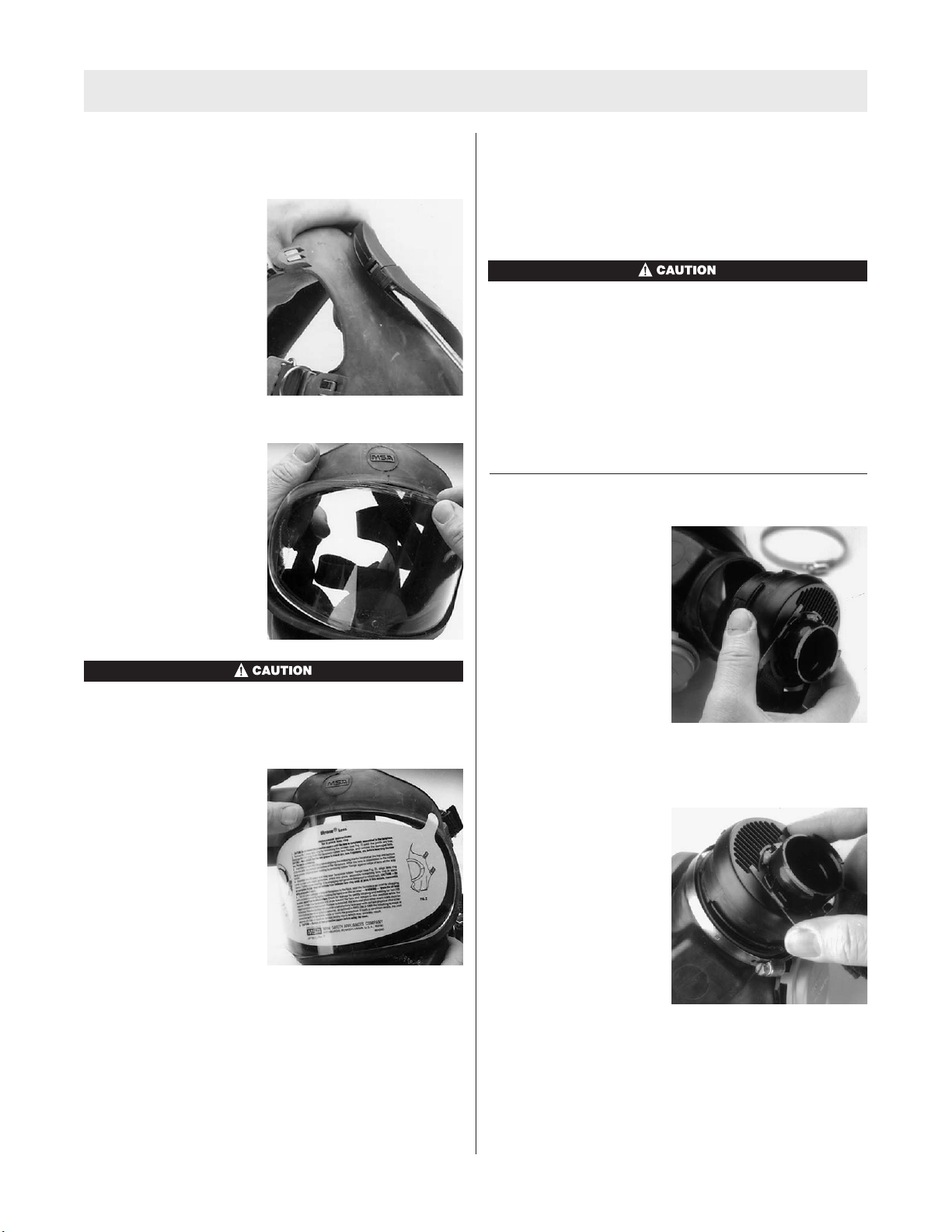
1. Unscrew the retainer
ring, using the face-
piece spanner wrench
(P/N 461828).
2. Turnthe facepiece upside down and shake out the
metal speaking diaphragm.
3. Check the speaking diaphragm for damage. Replace it
if it is wornor damaged.
4. Check the speaking diaphragm gasket or O-ring.
Replace the gasket or O-ring if either is wornor dam-
aged.
The flat gasket (used on old-style facepieces) and the
O-ring (used on the new design) are not interchange-
able. Replace the gasket with the P/N 83630 gasket
only. Replace the O-ring with the P/N 629935 O-ring
only.Failureto follow this warning may cause inhala-
tion of contaminant and result in serious respiratory
injury or death.
5. To reassemble the speaking diaphragm, place the
gasket or o-ring in the groove of the speaking
diaphragm housing.
6. Place the speaking
diaphragm in the hous-
ing so that the rolled lip
rests on the gasket or
o-ring.
Be sure that the crimped side of the speaking diaphragm
is facing up (away from the gasket or o-ring).
7. Replace the retainer ring and tighten, using the span-
ner wrench.
8. Don the facepiece and check the face-to-facepiece
seal. Follow the steps in the Facepiece Fit Check.
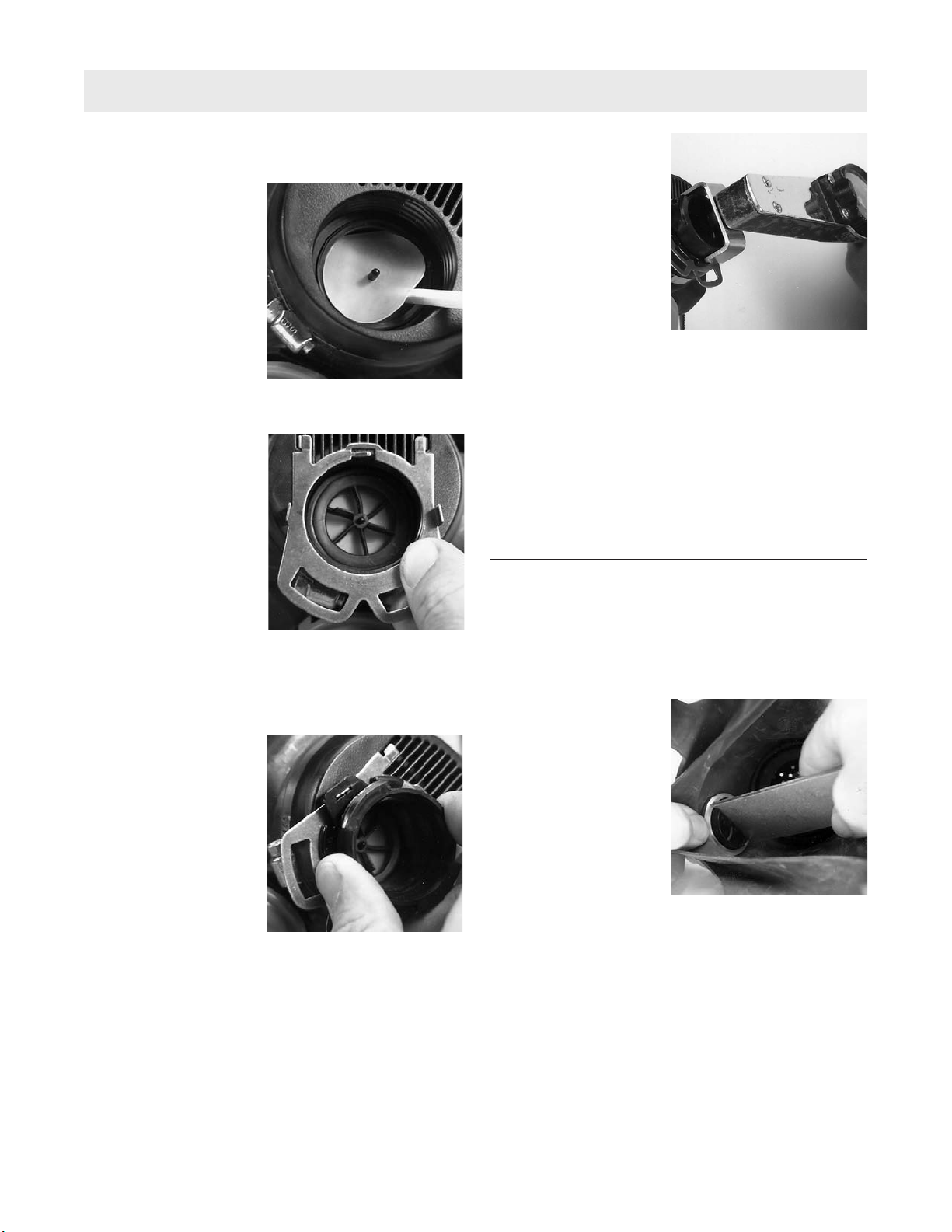
INHALATION DISC VALVE
1. Use the spanner
wrench (P/N 496317).
Press the adapter slip
nut in. Turnthe wrench
counter-clockwise (left)
to unthread the
adapter.
2. Lift the neckstrap retaining ring off the housing. Note
how the "fingers’’ line up in the housing.
3. Lift the spider gasket
out of the coupling nut
housing by its tab.
4. Remove the valve disc from the coupling nut housing.
If you cannot grasp the disc with your fingers, use a
blunt object, such as a ballpoint pen to lift one edge,
then remove the disc. Be careful not to tear the soft
disc.
5. Inspect the disc for tears or punctures. The disc
should be very soft and pliable. Install a new disc if it
is damaged or hardened.
9TAL 502 (L) Rev. 0 - 10064385
ULTRAVUE FACEPIECE REPAIR
6. To install the inhalation disc valve:
a. Press the valve disc on the pin in the coupling
housing.
b. Carefully tuck all
edges of the disc
under the housing
lip.
c. Replace the spider gasket (tab up) and press it on
the pin.
d. Place the neckstrap
retaining ring on the
housing. Line up the
"fingers’’ with the
housing.
e. Place the locking ring on the adapter.
f. Insert the adapter assembly through the hole in the
retaining ring. Startto thread the adapter slip nut
into the speaking diaphragm housing.
g. Turnthe adapter so
that the bayonets are
horizontal. Hand-
tighten the slip nut
until the two adapter
"wings" lock into the
two large tabs in the
retaining ring. Make
sure that each of the
two large tabs on the
retaining ring is fully
seated in both of the
slots on the adapter "wings."
h. Using the spanner
wrench, tighten the
adapter slip nut until
the slip nut locks
into the spring finger
on the retaining ring.
Continue to tighten
the slip nut so that
the adapter seals
against the spider
gasket. The slip nut
should be tightened
12 to 27 in-lb.
i. Verify each of the following features:
• The adapter bayonets are locked into a horizontal
orientation and can NOT be rotated;
• The slip nut is threaded completely into the face
piece and locked securely; it can NOT be rotated;
• The metal retaining ring is locked into position
and can NOT be rotated;
• There is no loose play in the assembly of parts.
PRESSURE DEMAND EXHALATION VALVE
1. Temporarily fold the headstraps back over the front of
the facepiece lens.
2. Pull the facepiece chin cup out so that you can see
the inside of the exhalation valve.
3. Use the facepiece
spanner wrench to
loosen the valve retain-
ing nut.
4. Unscrew and remove the retaining nut. Then, grasp
the valve cover and gently pull the valve out from the
underside of the facepiece.
Note: The pressure demand exhalation valve is replaced
as a unit. No replacement parts are available. All compo-
nents of each valve must be maintained as a unit. When
cleaning the valve, do not interchange parts.
5. Installing the pressure demand exhalation valve in the
facepiece:
a. Inspect the facepiece rubber for tears or cracks.
Replace the facepiece if it is damaged. Clean the area
around the facepiece mounting hole if necessary.
10
TAL 502 (L) Rev. 0 - 10064385
ULTRAVUE FACEPIECE REPAIR
Note: Rub a small amount of Never-Seez (P/N 29527) on
the valve threads.
b. Line up the exhalation valve threads with the face-
piece mounting hole. Place one hand inside the
facepiece and stretch the hole slightly.
c.Push the valve threads into the facepiece. Use a
"threading" motion to insert the valve until the valve
body rests against the facepiece rubber.
Note: The "MSA" logo on the exhalation valve cover does
not have to be aligned to any special position.
d. Pull the facepiece chin cup back so that you can
see the valve, then thread the retaining nut on.
e. Tighten the retaining nut, using the spanner wrench
(P/N 461828). Reposition the facepiece headstrap.
6. Inspect the exhalation valve.
7. Visually inspect the spring to see that it is located
properly in its socket.
Donot store the facepiece with the headstraps
stretched over the lens. Doing so may distort the seal-
ing surface and affect the facepiece seal.
8. Don the facepiece and check the face-to-facepiece
seal. Follow the steps in the Facepiece Fit Check.
11 TAL 502 (L) Rev. 0 - 10064385
NOTES
12
TAL 502 (L) Rev. 0 - 10064385
NOTES
13 TAL 502 (L) Rev. 0 - 10064385

Other manuals for PremAire System

5

Other MSA Safety Equipment manuals

MSA OptimAir 6HC User manual

MSA

MSA OptimAir 6HC User manual

MSA SSR 30/100 User manual

MSA

MSA SSR 30/100 User manual

MSA Vest Style User manual

MSA

MSA Vest Style User manual

MSA 10110162 Operation instructions

MSA

MSA 10110162 Operation instructions

MSA ProtoAir FPA-W44 User manual

MSA

MSA ProtoAir FPA-W44 User manual

MSA BD mini User manual

MSA

MSA BD mini User manual

MSA SURETYMAN SRS15 Installation instructions

MSA

MSA SURETYMAN SRS15 Installation instructions

MSA V-Gard HP Low User manual

MSA

MSA V-Gard HP Low User manual

MSA Sure-Climb SFPLS350 Series User manual

MSA

MSA Sure-Climb SFPLS350 Series User manual

MSA Gallet F1 XF User manual

MSA

MSA Gallet F1 XF User manual

MSA V-TEC SRL User manual

MSA

MSA V-TEC SRL User manual

MSA FP Pro User manual

MSA

MSA FP Pro User manual

MSA VAUTEX ELITE 3S-L User manual

MSA

MSA VAUTEX ELITE 3S-L User manual

MSA Gravity Sure-Line Operation instructions

MSA

MSA Gravity Sure-Line Operation instructions

MSA G1 SCBA User manual

MSA

MSA G1 SCBA User manual

MSA Kwik Draw User manual

MSA

MSA Kwik Draw User manual

MSA V-FLEX Operation instructions

MSA

MSA V-FLEX Operation instructions

MSA OptimAir 3000 User manual

MSA

MSA OptimAir 3000 User manual

MSA Latchways PRD 68220 User manual

MSA

MSA Latchways PRD 68220 User manual

MSA Ultima X Series User guide

MSA

MSA Ultima X Series User guide

MSA V-GARD 900 Series User manual

MSA

MSA V-GARD 900 Series User manual

MSA Gravity User manual

MSA

MSA Gravity User manual

MSA AUER 3S-Basis Plus User manual

MSA

MSA AUER 3S-Basis Plus User manual

MSA PremAire Cadet Escape Respirator Setup guide

MSA

MSA PremAire Cadet Escape Respirator Setup guide

Popular Safety Equipment manuals by other brands

ABS Safety Lock Loop installation manual

ABS Safety

ABS Safety Lock Loop installation manual

Kramer OWB-1G/65/EU quick start

Kramer

Kramer OWB-1G/65/EU quick start

Kentek XVT KFPG-6001 instructions

Kentek

Kentek XVT KFPG-6001 instructions

Safety 1st Wide & Sturdy Sliding Gate GA089 user guide

Safety 1st

Safety 1st Wide & Sturdy Sliding Gate GA089 user guide

Falltech 7324 User instruction manual

Falltech

Falltech 7324 User instruction manual

Finsterwalder Paralock 3 instruction manual

Finsterwalder

Finsterwalder Paralock 3 instruction manual

BUCKINGHAM MFG Ergovation Series Assembly instructions

BUCKINGHAM MFG

BUCKINGHAM MFG Ergovation Series Assembly instructions

Petzl TOP manual

Petzl

Petzl TOP manual

Coba COBAelite ESD Installation guidelines

Coba

Coba COBAelite ESD Installation guidelines

Silverline 254301 manual

Silverline

Silverline 254301 manual

MS3C MS3C-300TSB manual

MS3C

MS3C MS3C-300TSB manual

Reliance 3092 operating instructions

Reliance

Reliance 3092 operating instructions

Platek BOULARD Assembly instructions

Platek

Platek BOULARD Assembly instructions

Capital Safety PROTECTA AM211 Specific instructions

Capital Safety

Capital Safety PROTECTA AM211 Specific instructions

SECUMAR 9 S Instructions for use

SECUMAR

SECUMAR 9 S Instructions for use

BARRON Exitronix CH900X Series installation instructions

BARRON

BARRON Exitronix CH900X Series installation instructions

Crewsaver Euro 100N owner's manual

Crewsaver

Crewsaver Euro 100N owner's manual

HOGERT HT5K177 user manual

HOGERT

HOGERT HT5K177 user manual

manuals.online logo
manuals.online logoBrands
  • About & Mission
  • Contact us
  • Privacy Policy
  • Terms and Conditions

Copyright 2025 Manuals.Online. All Rights Reserved.