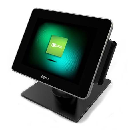
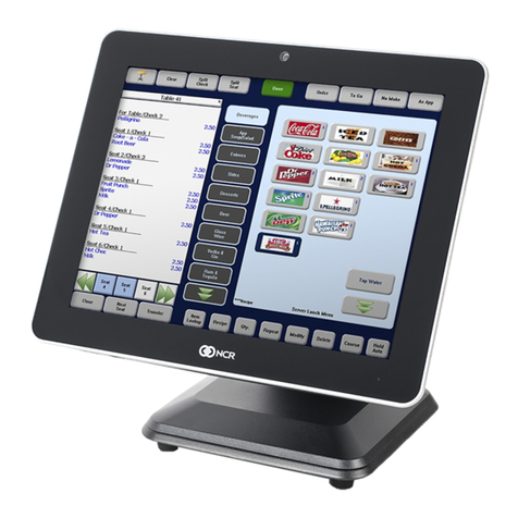
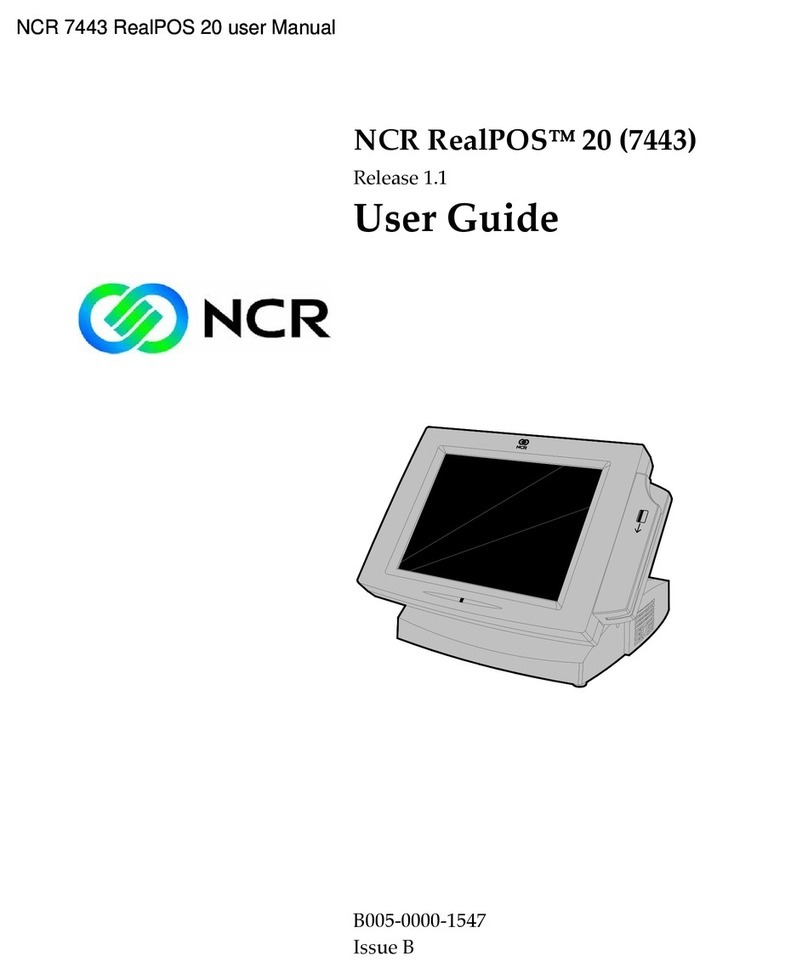
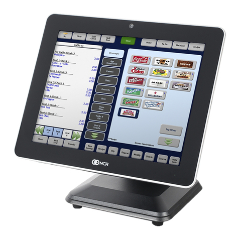
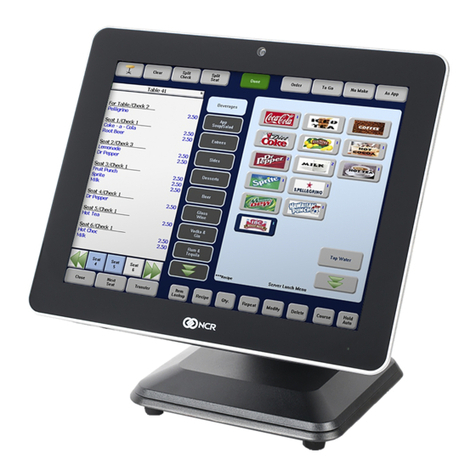
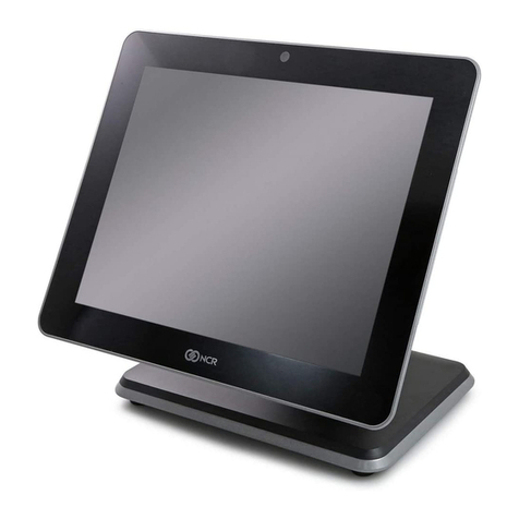
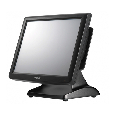
NCR RealPOS 25 Operating instructions

SITE PREPARATION GUIDE
NCR RealPOS 25 (7610)POS
Release 2.0
B005-0000-2018
Issue C

The product described in this book is a licensed product of NCR Corporation.
NCR is a registered trademark of NCR Corporation. NCR RealPOS is a trademark of NCR Corporation in the United States
and/or other countries. Other product names mentioned in this publication may be trademarks or registered trademarks of their
respective companies and are hereby acknowledged.
The terms HDMI and HDMI High-Definition Multimedia Interface, and the HDMI Logo are trademarks or registered trademarks
of HDMI Licensing LLC in the United States and other countries.
Where creation of derivative works, modifications or copies of this NCR copyrighted documentation is permitted under the terms
and conditions of an agreement you have with NCR, NCR's copyright notice must be included.
It is the policy of NCR Corporation (NCR) to improve products as new technology, components, software, and firmware become
available. NCR, therefore, reserves the right to change specifications without prior notice.
All features, functions, and operations described herein may not be marketed by NCR in all parts of the world. In some instances,
photographs are of equipment prototypes. Therefore, before using this document, consult with your NCR representative or NCR
office for information that is applicable and current.
To maintain the quality of our publications, we need your comments on the accuracy, clarity, organization, and value of this book.
Please use the link below to send your comments.
Documentation Feedback
Copyright © 2010
By NCR Corporation
Duluth, GA U.S.A.
All Rights Reserved

iii
Preface
Audience
This book is written for hardware installer/service personnel, system integrators, and
field engineers.
Notice: This document is NCR proprietary information and is not to be disclosed or
reproduced without consent.
Safety Requirements
The NCR RealPOS 25 conforms to all applicable legal requirements. To view the
compliance statements see the NCR RealPOS Terminals Safety and Regulatory Statements
(B005-0000-1589).
Caution: The on/off switch is a logic switch only. The AC line voltage primaries are
live at all times when the power cord is connected. Therefore, disconnect the AC power
cord before opening the unit to install features or service this terminal.
Caution: This product does not contain user serviceable parts. Servicing should only
be performed by a qualified service technician.
Fuse Replacement
Warning: For continued protection against risk of fire, replace only with the same
type and ratings of fuse.
Attention: Pour prévenir et vous protéger contre un risque de feu, remplacer la fusible
avec une autre fusible de même type, seulement.
Lithium Battery Warning
Warning: Danger of explosion if battery is incorrectly replaced. Replace only with
the same or equivalent type as recommended by the manufacturer. Discard used
batteries according to the manufacturer's instructions.
Attention: Il y a danger d'explosion s'il y a remplacement incorrect de la batterie.
Remplacer uniquement avec une batterie du même type ou d'un type recommandé par
le constructeur. Mettre au rébut les batteries usagées conformément aux instructions du
fabricant.
Battery Disposal (Switzerland)
Refer to Annex 4.10 of SR814.013 for battery disposal.

iv
IT Power System
This product is suitable for connection to an IT power system with a phase-to-phase
voltage not exceeding 240 V.
Peripheral Usage
This terminal should only be used with peripheral devices that are certified by the
appropriate safety agency for the country of installation (UL, CSA, TUV, VDE) or those
which are recommended by NCR Corporation.
Warning: DO NOT connect or disconnect the transaction printer while the terminal
is connected to AC power. This can result in system or printer damage.
Warning: DO NOT connect or disconnect any serial peripherals while the terminal
is connected to AC power. This can result in system or printer damage.
Grounding Instructions
In the event of a malfunction or breakdown, grounding provides a path of least
resistance for electric current to reduce the risk of electric shock. This product is
equipped with an electric cord having an equipment-grounding conductor and a
grounding plug. The plug must be plugged into a matching outlet that is properly
installed and grounded in accordance with all local codes and ordinances. Do not
modify the plug provided – if it will not fit the outlet, have the proper outlet installed by
a qualified electrician. Improper connection of the equipment-grounding conductor can
result in a risk of electric shock.
The conductor with insulation having an outer surface that is green with or without
yellow stripes is the equipment-grounding conductor.
If repair or replacement of the electric cord or plug is necessary, do not connect the
equipment-grounding conductor to a live terminal. Check with a qualified electrician or
service personnel if the grounding instructions are not completely understood, or if you
are in doubt as to whether the product is properly grounded.
Use only 3-wire extension cords that have 3-prong grounding plugs and 3-pole
receptacles that accept the product’s plug. Repair or replace damaged or worn cords
immediately.
References
•NCR RealPOS 25 User Guide (B005-0000-2017)
•NCR RealPOS 25 Hardware Service Manual (B005-0000-2019)
•NCR RealPOS 25 Parts Identification Manual (B005-0000-2020)
v
Table of Contents
NCR RealPOS 25 Terminal Site Preparation
Introduction 1
Product IDs 1
Customer Responsibilities 2
Third Party Peripheral Certification 3
LAN Communications 3
Environmental Requirements 4
Barometric Pressure 4
Temperature 4
Humidity 4
Dimensions 5
Terminal w/MSR 5
Terminal and Table Top Stand Dimensions 6
Terminal and Table Top Stand w/Power Supply Enclosure 6
Terminal w/Customer Display Dimensions 7
7409-K502 Flush Wall Mount Dimensions 7
VESA Mounting Hole Dimentions 8
NCR 5943 LCD / 5967 12-Inch Touch LCD Dimensions 9
5943 LCD / 5967 15-Inch Touch LCD Dimensions 9
NCR 5976 2x20 LCD Dimensions 10
Tall Pole Mount 11
Base Plate Mounting Hole Dimensions 12
NCR 5982 6.5-Inch LCD Dimensions 12
Power Supply Dimensions 13
Power Supply Bracket 13
NCR 5932-5xxx USB Big Ticket POS Keyboard Dimensions 14
5932-65xx PS/2 Compact Keyboard Dimensions 14
NCR 5932-66xx USB Compact Keyboard Dimensions 15
NCR 7167 Printer Dimensions 15
NCR 7168 Printer Dimensions 16
NCR 7197 Thermal Receipt Printer Dimensions 16
NCR 7198 Thermal Receipt Printer Dimensions 17

vi
NCR 2181 Cash Drawer Dimensions 17
NCR 2183 Compact Cash Drawer Dimensions 18
NCR 2185 Flip Top Drawer Dimensions 18
NCR 2186 Compact Cash Drawer Dimensions 19
Component Weights 19
Shipping Weight Estimate 20
Service Clearance Requirements 20
Airflow Requirements 21
Electrical Requirements 22
7610 Terminal Power Requirements 22
Peripheral Power Requirements 22
AC Store Wiring Requirements 22
Cable Routing 23
Customer Display Configuration 25
Custom Enclosures 26
Appendix A: TransientProtection
AC Power Line Transient Protection 1
Data Line Transient Protection 2
Revision Record
Issue Date Remarks
A Oct 2010 First Issue
B Aug 2012 Release 1.1
C June 2013 Release 2.0

NCR RealPOS 25 Terminal Site Preparation
Introduction
This document provides the information necessary to prepare a site to NCR
specifications prior to installing an NCR RealPOS 25 terminal (also referred to as the
NCR 7610). Prepare the site properly before installing the terminal because site
preparation deficiencies may be difficult to detect and correct after installation.
Product IDs
Major Model CPU
7610-5020 Intel Atom D2550 Dual Core 1.86G Hz, 2 GB DDR3, Diskless

2 NCR RealPOS 25 Terminal Site Preparation
Customer Responsibilities
Before installing the system, the customer must perform or provide the following:
• When required by NCR, provide the NCR Customer Services representative with
appropriate drawings that indicate:
• Equipment location
• Site wiring (power and communications, paths and lengths)
• Location of other equipment that may generate electrical noise, electromagnetic
interference, or heat
• Make building alterations necessary to meet wiring and other site requirements
• Provide and install all communications cables, wall jacks, special connectors, and
associated hardware
• Provide and install necessary power distribution boxes, conduits, grounds, lightning
protection devices, and associated hardware
• Ensure all applicable codes, regulations, and laws (including, but not limited to,
electrical, building, safety, and health) are met
• Provide and install auxiliary power or other equipment as required
• Provide storage or service areas as required
• Meet all system/unit environmental requirements
• Provide and install floor coverings and environment systems that limit or control
static electricity build-up and discharge
In general, keep the NCR equipment area free from dust, smoke, lint, and other
particles. Restrict smoking, eating, and drinking around the equipment. Avoid locating
the equipment near other machines that generate ink, carbon, and paper dust particles.

NCR RealPOS 25 Terminal Site Preparation 3
Third Party Peripheral Certification
Third party peripherals must be certified with the POS terminal or a potential ESD issue
can occur. Third party peripherals include any electrically powered devices connected
to the POS terminal that is not an NCR branded product or a certified solution
advocated by NCR. Examples of third party products include printers, external CD-
ROM drives, cash drawers, cigarette boxes, pin pad devices, etc.
Peripherals tend to be less sensitive to electrostatic damage when directly grounded
through their power cords. If the peripheral is powered by the terminal and has no
dedicated ground, then all of the ESD energy is coupled into the port connection. Some
devices may require the use of an in-line galvanic isolator/surge protector in order to
prevent problems.
The NCR TPP/SCER process is designed to evaluate third party peripherals and
determine whether additional protective devices are needed.
The NCR Workstation and Peripherals AC Wiring Guide (BST0-2115-53) contains additional
information on this subject.
LAN Communications
The NCR 7610 Terminal supports Ethernet 10/100/1000baseT Local Area Network (LAN)
communication protocol. For Ethernet communications wiring specifications, refer to
the NCR Ethernet Communication Wiring Guide (BST0-2118-82).

4 NCR RealPOS 25 Terminal Site Preparation
Environmental Requirements
Barometric Pressure
The terminal operates within the following barometric pressure conditions:
• Maximum operating altitude: 3,000 m (9,843 ft.)
• Operating range of pressure: 105 to 69 kPa (15.2 to 10.0 lb./in.)
Temperature
The terminal operates over the temperature ranges shown below. Avoid continuous
operation at, near the indicated temperature extremes, or in locations where the
temperature changes beyond the restrictions.
Temperature Parameter Restriction
Operating 5°C to 40°C (41°F to 104°F), dry bulb
Storage -10°C to 50°C (14°F to 122°F), three months
Shipping -40°C to 60°C (-40°F to 140°F), one week
Humidity
The terminal operates within the humidity ranges shown below. Avoid continuous
operation at, near the indicated humidity extremes, or in locations where the humidity
changes beyond the restrictions. Never expose the terminal to condensation.
Humidity Type Restriction
Relative 10% to 90%
Maximum change rate 10%/60 minutes
Storage 10% to 90% relative humidity, three months
Shipping 5% to 95% relative humidity, one week

NCR RealPOS 25 Terminal Site Preparation 5
Dimensions
Terminal w/MSR

6 NCR RealPOS 25 Terminal Site Preparation
Terminal and Table Top Stand Dimensions
Terminal and Table Top Stand w/Power Supply Enclosure

NCR RealPOS 25 Terminal Site Preparation 7
Terminal w/Customer Display Dimensions
7409-K502 Flush Wall Mount Dimensions
Note: The Terminal Cable Cover cannot be fully opened when using the Flush Wall
Mount but can be easily removed to access the cables and power switch.

8 NCR RealPOS 25 Terminal Site Preparation
VESA Mounting Hole Dimentions
Third?Party Mounts can be designed for the 7610 Display Head. The back panel of the
7610 has VESA compliant screw holes (M4) that are to be used for this purpose. The M4
screws should not exceed 6 mm plus the thickness of the mounting bracket in length.

NCR RealPOS 25 Terminal Site Preparation 9
NCR 5943 LCD / 5967 12-Inch Touch LCD Dimensions
5943 LCD / 5967 15-Inch Touch LCD Dimensions

10 NCR RealPOS 25 Terminal Site Preparation
NCR 5976 2x20 LCD Dimensions

NCR RealPOS 25 Terminal Site Preparation 11
Tall Pole Mount
There are four different length posts available for the 5976 display, in four inch
increments.
Note: Heights greater than 215 mm (8.5 in.) should be screwed to the counter top.

12 NCR RealPOS 25 Terminal Site Preparation
Base Plate Mounting Hole Dimensions
NCR 5982 6.5-Inch LCD Dimensions

NCR RealPOS 25 Terminal Site Preparation 13
Power Supply Dimensions
Power Supply Bracket

14 NCR RealPOS 25 Terminal Site Preparation
NCR 5932-5xxx USB Big Ticket POS Keyboard Dimensions
5932-65xx PS/2 Compact Keyboard Dimensions
Other manuals for RealPOS 25
1
This manual suits for next models
2
Table of contents
Other NCR Touch Terminal manuals