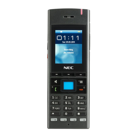
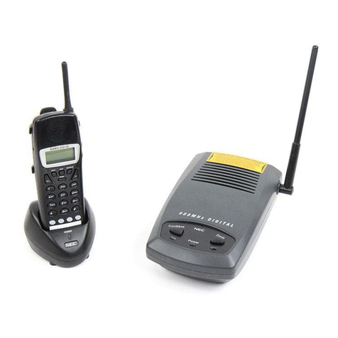
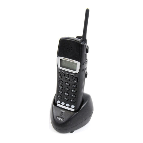
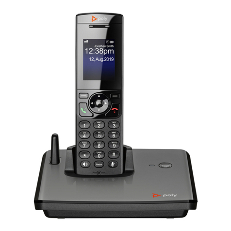
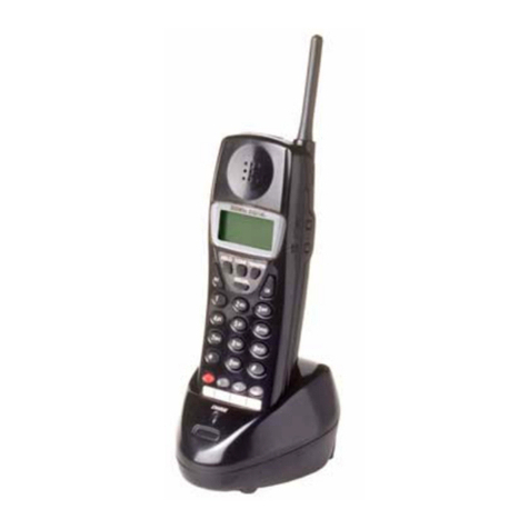
NEC 910i User manual

910i
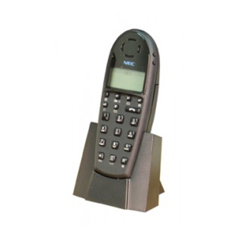
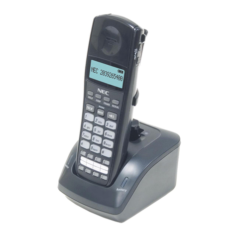
Cordless Telephone
Installation and
User Guide
1. Installation 2. Features 3. Specifications / Parts List 4. Index

This manual has been developed by NEC America, Inc. It is intended for the use of its customers and service
personnel, and should be read in its entirety before attempting to install or program the system. Any comments
or suggestions for improving this manual would be appreciated. Forward your remarks to:
NEC America, Inc., Corporate Networks Groups
4 Forest Parkway
Shelton, CT 06484
cng.nec.com
Nothing contained in this guide shall be deemed to be, and this guide does not constitute, a warranty of, or
representation with respect to, any of the equipment covered. This guide is subject to change without notice and
NEC America has no obligation to provide any updates or corrections to this guide. Further, NEC America also
reserves the right, without prior notice, to make changes in equipment design or components as it deems a
ppropriate. No representation is made that this guide is complete or accurate in all respects and NEC America
shall not be liable for any errors or omissions. In no event shall NEC America be liable for any incidental or
consequential damages in connection with the use of this guide.
© 2002 by NEC America, Inc. All Rights Reserved
Printed in U.S.A.

1-1
1. Installation
Section 1
Installation
In this section Page
Precautions . . . . . . . . . . . . . . . . . . . . . . . .1-2
Installation . . . . . . . . . . . . . . . . . . . . . . . .1-6
Selecting the Installation Location . . . . . . . .1-6
Connecting the Telephone Line . . . . . . . . . .1-6
Connecting the Telephone Cord . . . . . . . . . .1-6
Tone/Pulse Switch . . . . . . . . . . . . . . . . . . . .1-6
Applying Power to the Base Unit . . . . . . . . .1-7
Applying Power to the Desktop Charger . . .1-7
Wall Installation . . . . . . . . . . . . . . . . . . . . . .1-8
Attaching the Belt Clip to the Handset . . . . .1-9
Installing the Handset Battery . . . . . . . . . .1-10
Charging the Handset Battery . . . . . . . . . . .1-10
Charging the Spare Battery . . . . . . . . . . . .1-10
Low Battery Indicator . . . . . . . . . . . . . . . .1-10
Cleaning the Battery Contacts . . . . . . . . . .1-11
Upgrading the Firmware . . . . . . . . . . . . . .1-12
Installating New Firmware ROM . . . . . . . .1-12
Optional Equipment . . . . . . . . . . . . . . . .1-13
Desk Phone . . . . . . . . . . . . . . . . . . . . . . . .1-13
Headset . . . . . . . . . . . . . . . . . . . . . . . . . . .1-13
System Programming . . . . . . . . . . . . . . .1-14
Troubleshooting . . . . . . . . . . . . . . . . . . .1-15

1-2
Precautions
Before you read anything else, please observe the following:
WARNING!
NEC America Inc. DOES NOT represent this unit to be waterproof. To reduce the risk of fire, electrical shock, or
damage to the unit, DO NOT expose this unit to rain or moisture.
BATTERY WARNING
• This equipment contains a rechargeable Nickel-Cadmium battery.
• Do not charge the rechargeable Nickel-Cadmium battery used in this equipment in any charger other than the one
designed to charge this battery as specified in this guide. Using another charger may damage the battery, or cause
the battery to explode.
• Do not remove or damage battery casing.
• Never throw the battery into a fire, disassemble it, or heat it.
RECYCLING NICKEL-CADMIUM BATTERIES
Nickel-Cadmium batteries must be disposed of properly.
Nickel-Cadmium cells are used in the battery pack. Please take your battery packs to a locatiom that recycles Nickel-
Cadmium batteries or call 1-800-822-8837 for more information.

1-3
Precautions
1. Installation
IMPORTANT ELECTRICAL CONSIDERATIONS
Warning: Please do not attempt to unplug any appliance during an electrical storm.
Unplug all electrical appliances when you know an electrical storm is approaching. Lightning can pass through your household
wiring and damage any device connected to it. This phone is no exception.
Caution: Changes or modifications to this product not expressly approved by NEC America, Inc. or operation of this product in any
way other than as detailed by this Operating Guide, could void your authority to operate this product.
TELEPHONE LINE PROBLEMS
The FCC and IC have granted the telephone company the right to disconnect service in the event that your phone causes prob-
lems on the telephone line. Also, the telephone company may make changes in facilities and services which may affect the opera-
tion of your unit. However, your telephone company must give adequate notice in writing prior to such actions to allow you time
for making necessary arrangements to continue uninterrupted service. If you are having trouble with your telephone service, you
must first disconnect your phone to determine if it is the cause of your problem. If you determine that it is the cause, you must
leave it disconnected until the trouble has been corrected.
Radio Interference
Radio interference may occasionally cause buzzing and humming in your cordless Handset, or clicking noises in the Base Unit.
This interference is caused by external sources such as a TV, refrigerator, vacuum cleaner, fluorescent lighting, computer equip-
ment, or electrical storm. Your unit is NOT DEFECTIVE. If these noises continue and are too distracting, please check around
your office to see what appliances may be causing the problem. In addition, we recommend that the Base not be plugged into a
circuit that also powers a major appliance because of the potential for interference. Be certain that the antenna on the unit is fully
extended when needed.
In the unlikely event that you consistently hear other voices or distracting transmissions on your phone, you may be receiving
radio signals from another cordless telephone or another source of interference. If you cannot eliminate this type of interference,
you need to change to a different channel. Finally, it should be noted that some cordless telephones operate at frequencies that
may cause interference to nearby TVs and VCRs. To minimize or prevent such interference, the base of the cordless telephone
should not be placed near or on top of a TV or VCR. If interference is experienced, moving the cordless telephone farther away
from the TV or VCR will often reduce or eliminate the interference.
More Than One Cordless Telephone
If you want to use more than one cordless telephone in your office, they must operate on different channels. Press the channel
(CH) key to select a channel that provides the clearest communication. There are 10 channels from which to choose.
Privacy
Note: Cordless phones are radio devices. Communications between the Handset and Base Unit of your cordless telephone are
accomplished by means of radio waves which are broadcasted over the open airways. Because of the inherent physical properties
of radio waves, your communications can be received by radio receiving devices other than your own cordless telephone unit.
Consequently, any communications using your cordless telephone may not be private.
1-4
Precautions
Important Safety Instructions
When using your telephone equipment, basic safety precautions should always be followed to reduce the risk of fire,
electrical shock, and injury to persons, including the following:
1. Read and understand all instructions.
2. Follow all warnings and instructions marked on the product.
3. Unplug this product from the wall outlet before cleaning. Do not use liquid cleaners or aerosol cleaners. Use a dry
cloth for cleaning.
4. Do not use this product near water; for example, near a sink or in a wet area.
5. Do not place this product on an unstable cart, stand, or table. The telephone may fall, causing serious damage to the
unit.
6. To protect the product from overheating, do not block or cover any slots or openings in the base unit. This product
should never be placed near or over a radiator or heat register. This product should not be placed in a built-in instal-
lation unless proper ventilation is provided.
7. This product should be operated only from the type of power source indicated on the marking label.
8. Do not allow anything to rest on the power cord.
Do not locate this product where the cord will be damaged by persons walking on it.
9. Do not overload wall outlets and extension cords, as this can result in the risk of fire or electrical shock.
10. Never put objects of any kind into this product through the base unit slots, as they may touch dangerous voltage
points or short out parts that could result in a risk of fire or electric shock. Never spill liquid of any kind on the
product.
11. To reduce the risk of electric shock, do not disassemble this product. Contact qualified service personnel when ser-
vice or repair work is required. Opening or removing covers may expose you to dangerous voltages or other risks.
Incorrect reassembly can cause electric shock when the appliance is subsequently used.
12. Unplug this product from the wall outlet and refer servicing to qualified personnel under the following conditions:
A. When the power supply cord is damaged or frayed.
B. If liquid has been spilled into the product.
C. If the product has been exposed to rain or water.
D. If the product does not operate normally when following the operating instructions. Adjust only those controls
that are covered by the operating instructions. Improper adjustment of other controls may result in damage, and
will often require extensive work by a qualified technician to restore the product to normal operation.
E. If the product has been dropped, or the cabinet has been
damaged.
F. If the product exhibits a distinct change in performance.
13. Do not use the telephone to report a gas leak in the vicinity of the leak.

1-5
Precautions
1. Installation
CAUTION: To reduce the risk of fire or injury to persons by the battery, read and follow these instructions:
1. Use only the appropriate type and size battery pack specified in this Operating Guide.
2. Do not dispose of the battery pack in a fire. The cell may explode.
3. Do not open or mutilate the battery pack. The released electrolyte is corrosive and may cause damage to the eyes or
skin. It may be toxic if swallowed.
4. Exercise care in handling the battery in order not to short the battery with conducting materials such as rings,
bracelets, and keys. The battery or conductor may overheat and cause burns.
5. Charge the battery pack provided with or identified for use with this product only in accordance with the instructions
and limitations specified in the instruction manual provided for this product.
6. Observe proper polarity orientation between the battery pack and battery charger.
SAVE THESE INSTRUCTIONS

1-6
Installation
Selecting the Installation Location
Select a location for the phone that avoids excessive heat or humidity. The base unit can be placed on a desk or tabletop near a
standard 120V AC outlet and telephone line jack. The base unit can also be mounted on a standard AT&T or GTE wall plate
using the Wall Mount Adaptor. If the phone is to be paired with a keyset, place both phones in the same area. Keep the base unit
and handset away from sources of electrical noise (motors, fluorescent lighting, computers). Each 910i Cordless Telephone unit
should be at least 5 feet away from any other 910i Cordless Telephone to avoid interference.
Connecting the Telephone Line
There are two types of phone outlets:
1) Modular Jack
Plug the telephone line cord from the base unit into a standard modular telephone jack.
2) Hardwired Jack
A modular jack converter (not included) is required. You may need to rewire when connecting the converter (making color-
coded connections).
Connecting the Telephone Cord
CAUTION:
• Never install telephone wiring during a lightning storm.
• Never touch uninsulated telephone wires or terminals unless the telephone line has been disconnected at the KSU.
• Use caution when installing or modifying telephone lines.
Tone/Pulse Switch
Be sure the TONE/PULSE switch is in the TONE position.
Line in
From
Telephone
Jack
85457D-7

1-7
Installation
1. Installation
Applying Power to the Base Unit
Use the supplied 10V adaptor.
Applying Power to the Desktop Charger
Use the supplied 9V AC adaptor. Wrap the power cord around the convenient notch on the bottom.
IMPORTANT! Route the power cord where it will not create a trip hazard, or where it could become chafed and create a fire or
other electrical hazard.
Note: The AC adaptors furnished with this phone may be equipped with a polarized line plug (a plug having one blade wider
than the other). This plug will fit into the power outlet only one way. If you are unable to insert the plug fully into the outlet, try
reversing the plug. Do not alter the shape of the blades of the polarized plug.
Note: If you cannot plug the AC adaptors into the outlet, contact someone about replacing the outlet.
Before using your phone, be sure to raise the antenna to the vertical position.

1-8
Installation
Wall Installation
Standard Wall Plate Mounting
This Phone is designed to be mounted on a standard AT&T or GTE wall plate. To attach
the wall mount stand to the Base Unit:
1. Slide the Wall Mount stand into the notches at the top of the Base Unit, push the
Wall Mount stand down and snap it into place.
2. Plug the AC Adapter into the Base Unit as previously described.
3. Place the AC Adapter cord inside the molded channel of the Wall Mount stand.
4. Plug one end of the short telephone cord into the LINE jack on the Base Unit.
Optionally, plug one end of an NEC keyset desk phone into the phone jack. Then
place the telephone cord(s) inside the molded channel(s) on the bottom of the Wall
Mount stand
5. Plug the other end of the short telephone cord into the modular wall jack.
6. Place the Base Unit on the posts of the wall plate and push down until it’s firmly seated.
7. Plug the AC Adapter into a standard 120V AC wall outlet. .
Note: Do not use an outlet controlled by a wall switch.
Direct Wall Mounting
If you do not have a standard wall plate, you can mount your phone directly on a wall.
Before mounting your phone, consider the following:
• Select a location away from electrical cables, pipes, or other items behind the mounting
location that could cause a hazard when inserting screws into the wall.
• Make sure the wall material is capable of supporting the weight of the Base Unit.
• Use #10 screws with anchoring devices suitable for the wall material where the Base Unit will be placed.
1. Insert two mounting screws into the wall 3-15/16 inchesapart. Allow about 3/16 of an inch between the
wall and screw heads for mounting the phone.
2. Plug and secure the AC Adapter cord by following steps 2 and 3 of theStandard Wall Plate Mounting.
3. Plug one end of the telephone line cord intothe LINE jack on the Base Unit.
Optionally, plug one end of a standard 2500 type desk phone into the PHONE
jack. Then place the telephone cord(s) inside the molded channel(s) on the bottom
of the Wall Mount stand.
4. Place the Base Unit on the posts of the wall screws and push down until it is
firmly seated.
5. Plug the other end of the short telephone cord into a telephone wall jack.
6. Plug the AC Adapter into a standard 120V AC wall outlet by following step 7 of the Standard
Wall Plate Mounting.

1-9
Installation
1. Installation
Desktop Charger Wall Mounting
The Desktop Charger is also designed to be wall mounted. You can mount your phone directly on a wall. Before mounting your
charging unit, consider the following:
• Select a location away from electrical cables, pipes, or other items behind the mounting location that could cause a hazard
when inserting screws into the wall.
• Make sure the wall material is capable of supporting the weight of the Desktop Charger.
• Use #10 screws with anchoring devices suitable for the wall material where the Desktop Charger will be placed.
1. Insert two mounting screws into the wall 1-9/10 inches apart. Allow about 3/16 of an inch
between the wall and screw heads for mounting the phone.
2. Plug the AC Adapter into the Desktop Charger as previously described. Wrap the AC Adapter cord
around the strain relief.
3. Place the Desktop Charger on the posts of the wall screws and push down until it is firmly seated.
4. Plug the AC Adapter into a standard
120V AC wall outlet.
Attaching the Belt Clip to the Handset
You can use the Belt Clip to attach the handset to your belt or pocket for convenient portability.
1. Slide the clip into the tab slot.
CAUTION: The Belt Clip is designed to fit sungly onto the handset.
2. Press firmly unti it snaps into place.
3. To remove, simply press the retaining clip in toward the Belt Clip blad and slide the clip up at the same time.

1-10
Installation
Installing the Handset Battery
1. Remove the battery cover from the handset by pressing the latch and sliding the cover down
until it comes off the handset.
2. Slide the top of the battery into position, then lower the bottom portion into place. Note that the
battery has positive and negative indications. Make sure to place the battery in the handset so
the negative is on the left and positive is on the right (the metal contacts should face down
toward the phone).
3. Securely close the battery compartment cover by sliding it up until it snaps into place.
Charging the Handset Battery
The rechargeable Nickel-Cadmium battery pack must be fully charged before using your phone for the first time. Charge the battery
without interruption for 5 hours. The unique design of the telephone and charger allows you to place the handset in the Desktop
Charger with or without the Belt Clip attached.
1. Place the phone in the front slot of the desktop charger. The dial pad should be facing out in order for the battery contacts to
connect.
2. Make sure the CHARGE 1 LED lights. If the LED doesn’t light, check to see that the AC adapter is plugged in, and that the
handset is making good contact with the battery contacts.
Charging the Spare Battery
The desktop charger of your phone is equipped with a Battery Charger for charging the optional spare battery. The battery pack
can be charged either in or out of the handset.
1. Place the spare battery into the battery slot. In order for the battery to charge correctly,
the metal contacts must face down into the charger
If the battery is not positioned correctly, the CHARGE 2 LED will not light.
2. Slide the spare battery pack into the second slot in the charger until the retaining clip snaps
over the top of the pack.
Make sure the CHARGE 2 LED lights. If the LED does not light, check to see that the AC
Adaptor is plugged in, and that the battery pack is seated into the Charging Compartment. Charge
the battery pack without interruption for 12-15 hours.
When charging is complete, press the latch back slightly to remove the battery if it is needed.
Otherwise, leave the battery in the Charging Compartment. It will not overcharge.
Low Battery Indicator
When the battery in the handset is low and needs to be charged, you will see a “LOW” warning icon on the display.
Return the handset to the desktop charger for charging or replace the handset battery with the spare battery.
When the Low Battery Indicator Appears While
On a Call In Standby Mode
All keys and functions are available None of the buttons operate
Handset beeps once every 3 seconds Handset beeps every 15 seconds for 3 minutes
Complete your call as quickly as possible Cannot make or receive a call
Replace the battery pack within 20 seconds to continue call Replace battery pack before making a call

1-11
Installation
1. Installation
Cleaning the Battery Contacts
To maintain a good charge, it is important to clean all charging contacts on the handset, desktop charger, and spare battery pack
about once a month. Use a pencil eraser or soft dry cloth. Do not use any liquids or solvents.
Contacts
Contacts
85457D- 29

1-12
Installation
Upgrading the Firmware
Use these instructions when upgrading the Firmware ROM in your 910i Cordless Telephone Base Unit. The
new ROM in your upgrade kit is a static-sensitive component. Be sure to follow the instructions below
carefully. Failure to follow proper anti-static precautions could damage your new firmware.
Removing Old Firmware EPROM:
1. Unplug the base unit from the line cord.
2. Attach a grounded wrist strap to your wrist and a grounded metal object (such as
CEU ground).
3. Remove the screws from the bottom of the base unit and remove the cover.
4. Using an IC puller, carefully remove the old Firmware ROM. Be careful not to rock
the ROM or bend the pins during removal.
Installing New Firmware ROM:
1. Remove the new Firmware ROM from the anti-static sleeve.
2. Following the illustration at right, carefully install the new ROM in the base.
●Pay careful attention to line up the notch in the ROM with the notch in
its socket. The notch should be on the edge that denotes pin “1”.
●Do not bend any pins when plugging in the ROM.
3. Discard the old ROM.
4. Replace the cover on the base unit and reinstall the four screws.
5. Plug the line cord into the base unit.
1
92266 - 2
strap
Key
Grounded wrist
1
92266 - 1
Grounded wrist
strap

1-13
Optional Equipment
1. Installation
Desk Phone
The cordless phone allows for the connection of an optional keyset phone. The system can be programmed so that the keyset
and/or the 910i Cordless Telephone rings. If there is no answer, it can then transfer to voice mail. This allows you to have a key-
set phone to use while at your desk, and when you need to be away from your desk, you can carry the cordless phone with you.
Refer to System Programming on page 1-14 for the required programming for this option.
Headset
The optional headset provides a handsfree option for your convenience. With the
headset installed, you can use the belt clip to carry the handset and conduct a
conversation using the headset.
To install the optional headset, open the cover over the HEADSET jack and plug
the headset in. (The headset jack should be 2.5mm.)
No other settings are required.
Operation of the phone is exactly the same as using the handset. However, you
will hear through the headset earphone and talk through the headset micro-
phone. The handset earpiece and microphone/mouthpiece are disconnected.
2
abc
5
jkl
6
mno
4
ghi
8
tuv
9
wxyz
7
pqrs
0
oper
#
3
def
1
85457D-17
25-Pair Station
Cable to CEU
Telco
RJ21X
"B" Block
Two Pair
Cross Connect
85457D-18
BLK
RED GRN
BLU-WHT
ORN-WHT WHT-ORN
WHT-BLU
YEL
625
Modular
Jack
To
Optional
NEC Keyset
Cordless
Power
Desk

1-14
System Programming
The following system programming is suggested for the best operation of your cordless phone:
Programming - i-Series System
In program 0004 - Automatic Extension Circuit Type Setup:
1. Have the system automatically set the circuit type for each extension (the cordless phone is identified as circuit type 1).
In program 1006 - Programming Functions Keys (or SC 851):
1. Assign a loop key to one of the function keys. The system default setting has the function keys programmed for
lines1 - 4. By assigning a loop key, all required lines can be accessed (enter code 1078 - option 2).
In program 0909 - Extension Ring Group Assignment:
1. Assign the cordless phone’s extension to a Ring Group.
In addition to the other normal keyset programming, the following programs can be set so an optional desk phone can be used in
addition to the cordless phone:
In program 1009 - Cordless/Desktop Extension Assignment:
1. Assign the extension number for the cordless phone first and then assign the extension for the desk phone.
In program 1006 - Programming Function Keys:
1. Program a function key to be a Call Coverage key for the cordless phone’s extension as well as the desk phone’s
extension. Assign the desk phone’s extension to the cordless phone and the cordless phone’s extension to the desk
phone (enter code 1036 + extension number).
In program 1016 - Multiple Directory Number Ring Assignment:
1. Set the ringing assignment for the Call Coverage key for both the cordless phone and desk phone’s extension (Option
1 allows the calls to ring the extension).
Programming - Onyx VSiSystem
In program E8 - Ringing Line Preference:
1. Enable Ringing Ling Preference for the cordless phone’s extension number.
In program KS - Programming Keys for Keysets:
1. Assign a loop key to one of the function keys. The system default setting has the function keys programmed for
lines
1 - 4. By assigning a loop key, all required lines can be accessed (To assign a Loop Key, enter ‘9’ in KS program).
In program E2 - Extension Circuit Type:
1. Enter the circuit type of “02” for the cordless phone’s extension number.
In addition to the other normal keyset programming, the following programs can be set so an optional desk phone can be used in
addition to the cordless phone:
In program E9 - Direct Termination or Operator Extension:
1. Enter the cordless phone’s extension number. At the prompt “DIR TERM OR OPR EXT”, enter the extension num-
ber of the desk phone.
In program KS - Programming Keys for Keysets:
1. For the desk phone, assign a Station Pickup key with the cordless phone’s extension number (to assign a Station
Pickup key, enter ‘S’ + extension number in KS program).

1-15
Troubleshooting
1. Installation
Troubleshooting Procedures
If your phone is not performing to your expectations, please try these simple steps. If you are still unable to resolve the problem,
contact your communications manager.
Problem Suggestion
Charge light won’t come • Make sure the AC Adaptor is plugged into the desktop charger
on when the handset is and wall outlet.
placed in the desktop • Make sure the handset is properly seated in the desktop charger.
charger • Make sure the battery pack is properly placed in the handset.
• Make sure that the charging contacts on the handset and desktop
charger are clean.
Conversation interrupted • Make sure that the base unit’s antenna is fully vertical.
frequently. • Move closer to the base unit.
Warning tone and NO • Move closer to the base unit.
SERVICE message.
Handset doesn’t ring. • The battery pack may be weak. Charge the battery for 5-6 hours.
• Make sure the base unit antenna is fully vertical.
• The handset may be too far away from the base unit.
• Ensure the Ringer ON/OFF switch is in the ON position.
Interference from other • Press the Channel (CH) key to switch channels.
cordless phone users. The channel can be changed while you are on an active call, but not
when you are dialing a telephone number. There are 10 channels
from which you can select.
Interference or noise in • Make sure the base unit is at least 3’ away from any computer
the handset. fax machine, printer, or TV (they generate radio waves)
• Make sure the antenna is in the upright position

1-16
Troubleshooting
- For Your Notes -

2-1
Section 2
Features
In this section Page
Basic Operation . . . . . . . . . . . . . . . . . . . . .2-5
Using the Handset . . . . . . . . . . . . . . . . .2-5
i-Series Features . . . . . . . . . . . . . . . . . . . .2-7
Basic Feature Operation . . . . . . . . . . . .2-9
Outside Calls . . . . . . . . . . . . . . . . . . . . . .2-9
Hold . . . . . . . . . . . . . . . . . . . . . . . . . . . .2-11
Intercom Calls . . . . . . . . . . . . . . . . . . . .2-12
Transfer . . . . . . . . . . . . . . . . . . . . . . . . .2-12
System Features . . . . . . . . . . . . . . . . .2-15
Abbreviated Dialing . . . . . . . . . . . . . . . .2-15
Account Codes . . . . . . . . . . . . . . . . . . . .2-16
Alarm . . . . . . . . . . . . . . . . . . . . . . . . . .2-16
Automated Attendant (VAU) . . . . . . . . .2-17
Barge In . . . . . . . . . . . . . . . . . . . . . . . . .2-17
Call Forwarding . . . . . . . . . . . . . . . . . . .2-17
Call Forwarding Off-Premise . . . . . . . . .2-18
Call Forward Follow Me . . . . . . . . . . . .2-19
Call Forward/DND Override . . . . . . . . .2-19
Call Waiting (Camp On) . . . . . . . . . . . .2-19
Callback . . . . . . . . . . . . . . . . . . . . . . . . .2-20
Caller ID . . . . . . . . . . . . . . . . . . . . . . . .2-20
Conference . . . . . . . . . . . . . . . . . . . . . . .2-21
Conference, Voice Call . . . . . . . . . . . . . .2-21
Department Calling . . . . . . . . . . . . . . . .2-21
Department Step Calling . . . . . . . . . . . .2-22
Directed Call Pickup . . . . . . . . . . . . . . .2-23
Do Not Disturb . . . . . . . . . . . . . . . . . . .2-23
Door Box . . . . . . . . . . . . . . . . . . . . . . . .2-23
Flash . . . . . . . . . . . . . . . . . . . . . . . . . . .2-24
Forced Trunk Disconnect . . . . . . . . . . . .2-24
Group Call Pickup . . . . . . . . . . . . . . . . .2-24
Headset . . . . . . . . . . . . . . . . . . . . . . . . .2-25
Hotline . . . . . . . . . . . . . . . . . . . . . . . . . .2-25
Last Number Redial . . . . . . . . . . . . . . . .2-25
Line Preference . . . . . . . . . . . . . . . . . . .2-26
Meet-Me Conference . . . . . . . . . . . . . . .2-26
Meet Me Paging . . . . . . . . . . . . . . . . . . .2-27
Message Waiting . . . . . . . . . . . . . . . . . .2-27
Microphone Cutoff . . . . . . . . . . . . . . . . .2-28
Multiple Directory Numbers . . . . . . . . .2-28
Night Service . . . . . . . . . . . . . . . . . . . . .2-28
Off Hook Signaling . . . . . . . . . . . . . . . .2-29
One-Touch Calling . . . . . . . . . . . . . . . . .2-30
2. Features

2-2
In this section Page
Paging . . . . . . . . . . . . . . . . . . . . . . . . . .2-30
Park . . . . . . . . . . . . . . . . . . . . . . . . . . . .2-31
Park and Page (VAU) . . . . . . . . . . . . . . .2-32
Personal Greeting . . . . . . . . . . . . . . . . . .2-32
Programmable Function Keys . . . . . . . .2-33
Reverse Voice Over . . . . . . . . . . . . . . . .2-35
Ringdown . . . . . . . . . . . . . . . . . . . . . . .2-36
Save Number Dialed . . . . . . . . . . . . . . .2-36
Secretary Call . . . . . . . . . . . . . . . . . . . .2-37
Selectable Display Messages . . . . . . . . .2-37
Serial Dial . . . . . . . . . . . . . . . . . . . . . . .2-38
Tandem Trunking . . . . . . . . . . . . . . . . . .2-39
Trunk Queuing . . . . . . . . . . . . . . . . . . . .2-39
Voice Announce Unit (VAU) Messages .2-40
Voice Mail . . . . . . . . . . . . . . . . . . . . . . .2-40
Voice Over . . . . . . . . . . . . . . . . . . . . . . .2-41
Voice Prompting Messages . . . . . . . . . . .2-42
Volume Controls . . . . . . . . . . . . . . . . . .2-43
Onyx VSi Features . . . . . . . . . . . . . . . . . .2-45
Basic Feature Operation . . . . . . . . . . .2-47
Outside Calls . . . . . . . . . . . . . . . . . . . . .2-47
Hold . . . . . . . . . . . . . . . . . . . . . . . . . . . .2-47
Intercom Calls . . . . . . . . . . . . . . . . . . . .2-48
Transfer . . . . . . . . . . . . . . . . . . . . . . . . .2-48
System Features . . . . . . . . . . . . . . . . .2-51
Account Codes . . . . . . . . . . . . . . . . . . . .2-51
Call Forwarding . . . . . . . . . . . . . . . . . . .2-51
Callback . . . . . . . . . . . . . . . . . . . . . . . . .2-52
Caller ID . . . . . . . . . . . . . . . . . . . . . . . .2-52
Camp-On . . . . . . . . . . . . . . . . . . . . . . . .2-53
Conference . . . . . . . . . . . . . . . . . . . . . . .2-54
Conference, Unsupervised . . . . . . . . . . .2-54
Directed Call Pickup . . . . . . . . . . . . . . .2-54
Display Messages . . . . . . . . . . . . . . . . .2-55
Flash . . . . . . . . . . . . . . . . . . . . . . . . . . .2-55
Group Call Pickup . . . . . . . . . . . . . . . . .2-55
Group Ring . . . . . . . . . . . . . . . . . . . . . .2-55
Headset . . . . . . . . . . . . . . . . . . . . . . . . .2-56
Hotline . . . . . . . . . . . . . . . . . . . . . . . . . .2-56
Intrusion (Barge-In) . . . . . . . . . . . . . . . .2-56
Last Number Redial . . . . . . . . . . . . . . . .2-57
Line Callback . . . . . . . . . . . . . . . . . . . . .2-57
Meet-Me Conference . . . . . . . . . . . . . . .2-58
Message Waiting . . . . . . . . . . . . . . . . . .2-58
Microphone Mute . . . . . . . . . . . . . . . . .2-58
Monitor . . . . . . . . . . . . . . . . . . . . . . . . .2-58
Operator Assistance . . . . . . . . . . . . . . . .2-59
Page Zone . . . . . . . . . . . . . . . . . . . . . . .2-59
Table of contents
Other NEC Cordless Telephone manuals

NEC
NEC G277 User manual

NEC
NEC Dterm Cordless II DTR-4R BK User manual

NEC
NEC DTL-12BT-1 - DT330 - Plus BCH Operating and installation instructions

NEC
NEC DTH-4R-1 User manual

NEC
NEC DTR-1R-2 User manual

NEC
NEC DTL-8LD-1 User manual

NEC
NEC Dterm Analog Cordless User manual

NEC
NEC Aspire Cordless II User manual

NEC
NEC G566 Operating and maintenance manual

NEC
NEC G577 User manual

NEC
NEC DTH-4R-2 - CORDLESS Lite II BLAC User manual

NEC
NEC IP3NA-BCH User manual

NEC
NEC NCS User manual

NEC
NEC DS1000/2000 User manual

NEC
NEC DTL-12BT-1 series User manual

NEC
NEC Dterm I Series User manual

NEC
NEC Dterm Cordless II User manual

NEC
NEC DS1000 User manual

NEC
NEC PSII User manual

NEC
NEC Dterm I Series User manual