Warning
Always make sure that the power to the wiring center
is disconnected before opening the case.
1
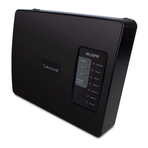
AKL04P Zone Pump Wiring Center
Installation and Wiring Guide
LED indications
Name Colour Meaning
Power •AKL04P is supplied with 120VAC power
Priority •On when a Priority is active
Zone 1 •Demand from zone 1 thermostat: pump active
Zone 2 •Demand from zone 2 thermostat: pump active
Zone 3 •Demand from zone 3 thermostat: pump active
Zone 4 •Demand from zone 4 thermostat: pump active
Use the AKL04P wiring center to simply and safely connect thermostats and corresponding pumps.
It can have two different physical configurations:
• One thermostat for each zone ( 4 thermostats in total )
• One group with one master SALUS thermostat and up to 3 slave thermostats. Link required on clock terminals
1-2 and 3-4 (see on the wiring diagram, front page)
Note:
1. You can add one pump for each zone (4 in total), one primary pump and one priority pump.
2. You can use SALUS thermostats or any other thermostat that is compatible for your system.
3. Make sure that the thermostats are all 24VAC.
Our recommendation is to use Salus thermostats.
For more details please check our website www.salusna.com
Installing and Connecting the AKL04P
A
Functioning Principles
1. Primary Pump
The primary pump is controlling the heating system and will be switched on when any zone is on.
Exception: If the DIP Switch for Priority is ON, and the DIP Switch for Primary status during priority OFF , then
the primary pump will be Off during a priority call.
2. Priority Pump
The priority pump, if enabled, is for controlling the domestic hot water. This will enable the functions of Zone
1 on a master unit only. When the Zone 1 thermostat calls for heat, the Priority pump will be ON and will run
for up to 1 hour, switching OFF all other zones. After 1 hour, all the zones will resume to their normal function.
To enable the Priority pump there needs to be a Zone 1 thermostat connected to the domestic hot water
control.
3. Zone Pumps
The Zone pumps will be activated when the thermostats are calling for heat, except when the priority zone is
activated.
4. Auxiliar Outputs
There are 3 volt free auxiliar outputs.
AUX: It will be active when any pump is ON and the Priority pump is OFF.
XX: It will be active when any zone is ON, including the Priority zone.
Zone 1 E/S: It will be active when there is a priority call for DHW, this is used to
override the boiler weather compensation.
5. Communication connections
The terminals (C1,C2, ) can be used to connect up to 4 slave Pump Wiring Centers to your
master Pump Wiring Center. The master wiring center needs to have the DIP switches set
as Master and the slave pump wiring centers will have the DIP switches set as slaves.
6. ZC / N Connector
When the Master switch is set to ON and the Priority Switch is set to OFF, the ZC/N connector
on the AKL04P can be used to enable or disable the unit based upon the output from the boiler
ZR/ZC 120V contact. When 120VAC is applied across ZC/N on the AKL04P, the unit will be
enabled; when 120VAC is not applied across the ZC/N contacts of the AKL04P, the unit will be
disabled and all pumps will be switched off.
DIP Switches function
DIP Switch Description
Master/Slave Choose the desired status for your Pump Wiring
Center
Priority ON/OFF When the Priority is ON, Zone 1 will operate as the
Priority zone
Exercise ON/OFF
When the Exercise is ON, each zone that has been
inactive for more than 72 hours will be switched
on for 30 sec.
Primary status during Priority ON/OFF When ON, the Primary pump will be active during
a Priority request.
Purge ON/OFF When ON, Zone 1 will operate for 2 extra minutes
after the Priority zone is switched o.
This equipment has been tested and found to comply with the limits for a Class B digital device,
pursuant to Part 15 of the FCC Rules. These limits are designed to provide reasonable protection
against harmful interference ina residential installation. This equipment generates uses and can
radiate radio frequency energy and, if not installed and used in accordance with the instructions,
may cause harmful interference to radio communications. However, there is no guarantee that
interference will not occur in a particular installation. If this equipment does cause harmful
interference to radio or television reception, which can be determined by turning the equipment
off and on, the user is encouraged to try to correct the interference by one or more of the following
measures:
• Reorient or relocate the receiving antenna.
• Increase the separation between the equipment and receiver.
• Connect the equipment into an outlet on a circuit different from that to which the receiver is
connected.
• Consult the dealer or an experienced radio/TV technician for help.
Changes or modifications not expressly approved by the party responsible for compliance could void
the user’s authority to operate the equipment.
This device complies with part 15 of the FCC Rules. Operation is subject to the following two
conditions: (1)This device may not cause harmful interference, and (2) this device must accept any
interference received, including interference that may cause undesired operation.
This Class B digital apparatus complies with Canadian ICES-003.
Cet appareil numérique de la classe B est conforme à la norme NMB-003 du Canada.
FCC Statement
Warning
Use the powercord connections that are
suitable for your system.
Power 120V
110mm/4.33in
110mm/4.33in
Thermostat
110mm/4.33in
3Use the proper wire connectors (purchased
separately) for a 120 VAC power suply
system.
After placing the wires through the wire connectors,
secure them by tightening the screws.
Remove the plastic cover by unscrewing the
4 screws.
Re-attach the plastic cover and secure it with
the 4 screws. Switch on the main power
supply to the unit. The red LED comes on.
7
Clip all wires and cables into their
correct positions.
Make the connections for the thermostats at the top
of the AKL04P and for the pumps at the bottom of
the wiring center.
Cable clamps are required to be fitted to the case
knock outs for ensuring that the cables are clamped.
4
Make sure that the fuses are each of 5 Amp,
slow blow, and in the correct position.
5
Attach the back of the AKL04P to the wall or
in a suitable location.
2
External timer
If you use non programmable thermostats and you
have the clock terminals connected on your slave
thermostats, the external timer can communicate
via NSB signal.
Note: You can set up your thermostats in Group 1,
Group 2 or as Stand alone.
6
4
4
Pump

